



7 hours ago
While I'm waiting to wrap up the final steps on my wife's Silvertone 2014, I started disassembly on the next project. One of the wife's friends liked the idea of a vintage radio for the front desk at her inn, especially if it could accommodate a Bluetooth connection but she wanted something small. This 54C was one of my very first (if not the very next) acquisitions after the 6K3, (eBay) though I paid more for it in April than I would pay for a radio today ($45, plus shipping). She likes this one for its size.
I've read through Ron's rebuild and modification of a 54C to eliminate the giant resistors out back and use more modern tubes. I'm not going to go to that extreme (though if the resistors themselves are bad I may need to get creative), but I may incorporate some of his tweaks if people think it would be beneficial.
For example, I know he added a safety capacitor (0.01 uF X1/Y2) between hot and neutral after the switch, and a 150K ohm resistor from the neutral side to chassis ground (part numbers 44 and 43 respectively on his updated schematic here: https://philcoradio.com/library/index.ph...4c-part-2/). I suspect his reasoning for those modifications is sound and I would be well served to do the same?
Also, as with the other radios I've worked on, I will add a new cord with polarized plug and move the switch onto the hot side with an inline fuse before the switch.
For those who are familiar with and/or have worked on this model before, are there any other suggestions you would have?
Also, before I start putting things back together (a long way off, still) I would like to iron out where is the ideal location to put a switch to cut between radio and aux input - would it be between the input to volume control and the junction of the volume control input with R21, R26, and C24?
While everything is still a learning experience for me, this will be my first complete teardown so I will be taking copious notes/sketches and photos along the way for my reference. It's not that I had a particular desire to take it all apart, but given how tight everything is inside, I can't see any other way to effectively check and replace resistors and capacitors inside the chassis. So I think this method is the only way to safely access it and will certainly be helpful to facilitate a good cleaning. I expect to put in all new wire because "why not" if it's all apart anyway. So far they're not like wires in the 6K3 with the crumbling insulation.
I won't be posting much in the way of updates, hopefully, at least not until it's time to start putting things back together. Tonight I started with just the removal of the 1st IF transformer assembly and oscillator coil assembly which are mounted to the same metal stand-off. Already checked resistance and primary and secondary of each ohms out to just about what the schematics say they should. Two resistors came with them, both of them significantly low, R11 (51K) at 37.7K (26% under) and R14 (5K) at 4.18K (16% under). Obviously R11 gets replaced, and I plan to do R14 as well, as this is not a chassis I want to dig through again in the future if these resistors go further from their intended values. Smaller, modern components can only help underneath, as well. Will be interesting to see how the rest of them test as I go along. Complete teardown makes testing out-of-circuit much easier, at least.
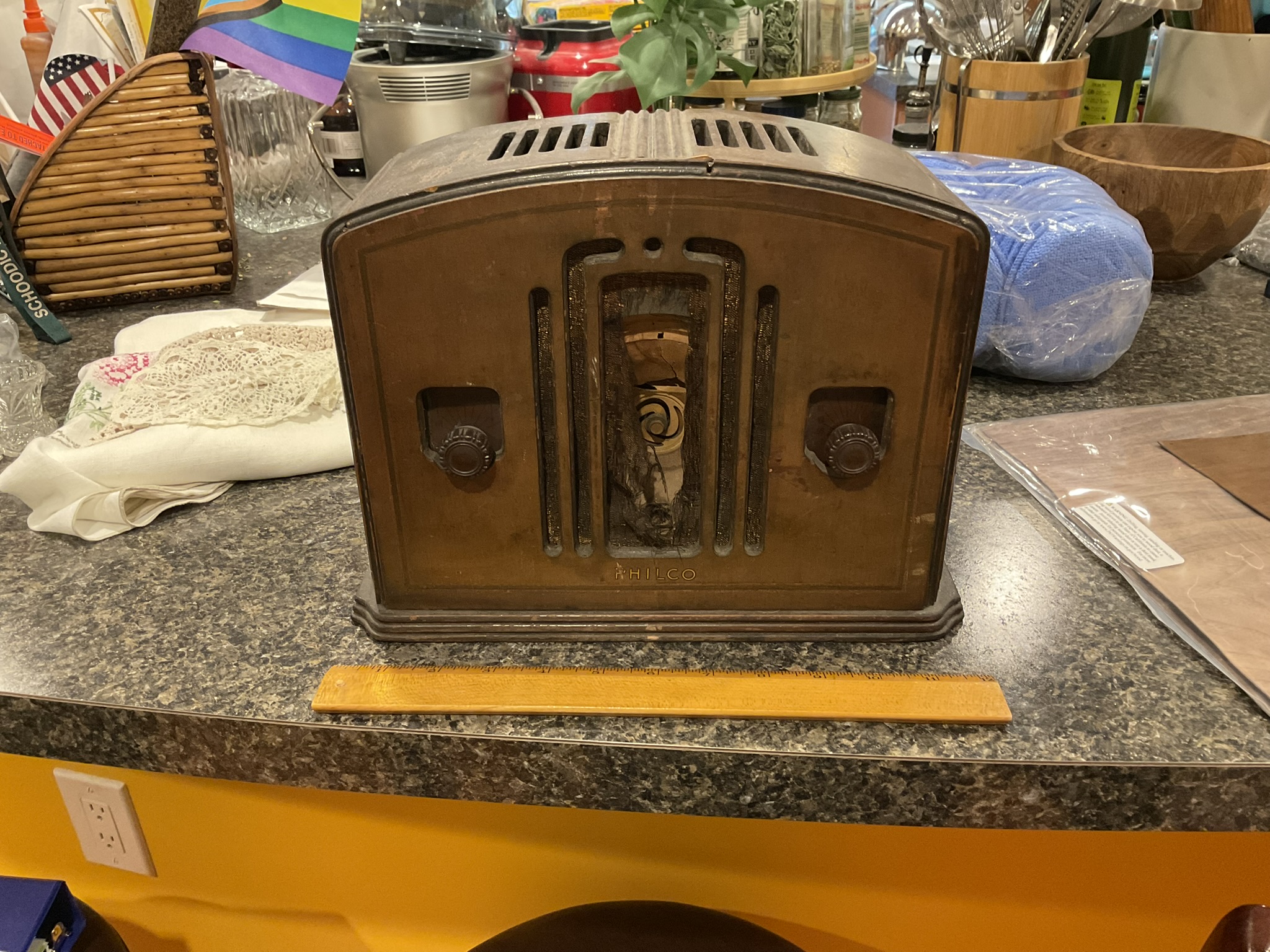
Definitely will get to try to repair the speaker cone or, failing that, attempt to recone it, and failing that, be in search of a new speaker. Probably should test the field and voice coils before hand.
Best wishes,
Roy
I've read through Ron's rebuild and modification of a 54C to eliminate the giant resistors out back and use more modern tubes. I'm not going to go to that extreme (though if the resistors themselves are bad I may need to get creative), but I may incorporate some of his tweaks if people think it would be beneficial.
For example, I know he added a safety capacitor (0.01 uF X1/Y2) between hot and neutral after the switch, and a 150K ohm resistor from the neutral side to chassis ground (part numbers 44 and 43 respectively on his updated schematic here: https://philcoradio.com/library/index.ph...4c-part-2/). I suspect his reasoning for those modifications is sound and I would be well served to do the same?
Also, as with the other radios I've worked on, I will add a new cord with polarized plug and move the switch onto the hot side with an inline fuse before the switch.
For those who are familiar with and/or have worked on this model before, are there any other suggestions you would have?
Also, before I start putting things back together (a long way off, still) I would like to iron out where is the ideal location to put a switch to cut between radio and aux input - would it be between the input to volume control and the junction of the volume control input with R21, R26, and C24?
While everything is still a learning experience for me, this will be my first complete teardown so I will be taking copious notes/sketches and photos along the way for my reference. It's not that I had a particular desire to take it all apart, but given how tight everything is inside, I can't see any other way to effectively check and replace resistors and capacitors inside the chassis. So I think this method is the only way to safely access it and will certainly be helpful to facilitate a good cleaning. I expect to put in all new wire because "why not" if it's all apart anyway. So far they're not like wires in the 6K3 with the crumbling insulation.
I won't be posting much in the way of updates, hopefully, at least not until it's time to start putting things back together. Tonight I started with just the removal of the 1st IF transformer assembly and oscillator coil assembly which are mounted to the same metal stand-off. Already checked resistance and primary and secondary of each ohms out to just about what the schematics say they should. Two resistors came with them, both of them significantly low, R11 (51K) at 37.7K (26% under) and R14 (5K) at 4.18K (16% under). Obviously R11 gets replaced, and I plan to do R14 as well, as this is not a chassis I want to dig through again in the future if these resistors go further from their intended values. Smaller, modern components can only help underneath, as well. Will be interesting to see how the rest of them test as I go along. Complete teardown makes testing out-of-circuit much easier, at least.
Definitely will get to try to repair the speaker cone or, failing that, attempt to recone it, and failing that, be in search of a new speaker. Probably should test the field and voice coils before hand.
Best wishes,
Roy


