I had found what I felt was a perfect candidate for a “modernization” from a 1933 design to 1940s standards – a somewhat rough Philco model 54C radio. In this radio, I plan to change its circuitry somewhat so that it uses newer octal tubes instead of the standard base tubes it originally used, as well as eliminate the two large power resistors which mounted above the chassis.
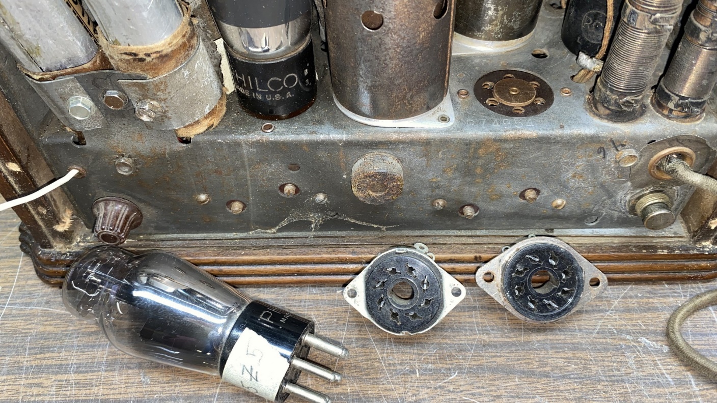
I happened to have a good selection of new-old-stock octal tube sockets in two different types – one type with ground terminals, and one type without.
Now, it was time to begin. The first thing I needed to do was to remove the chassis from the cabinet. I pulled the two knobs from the front. Many of these cigar box pee-wee Philco sets are missing their dial pointer; this set surprisingly still had its pointer. This, too, was carefully removed. Once these parts were set aside in a safe place, I carefully laid the radio on its front and removed the chassis mounting screws.
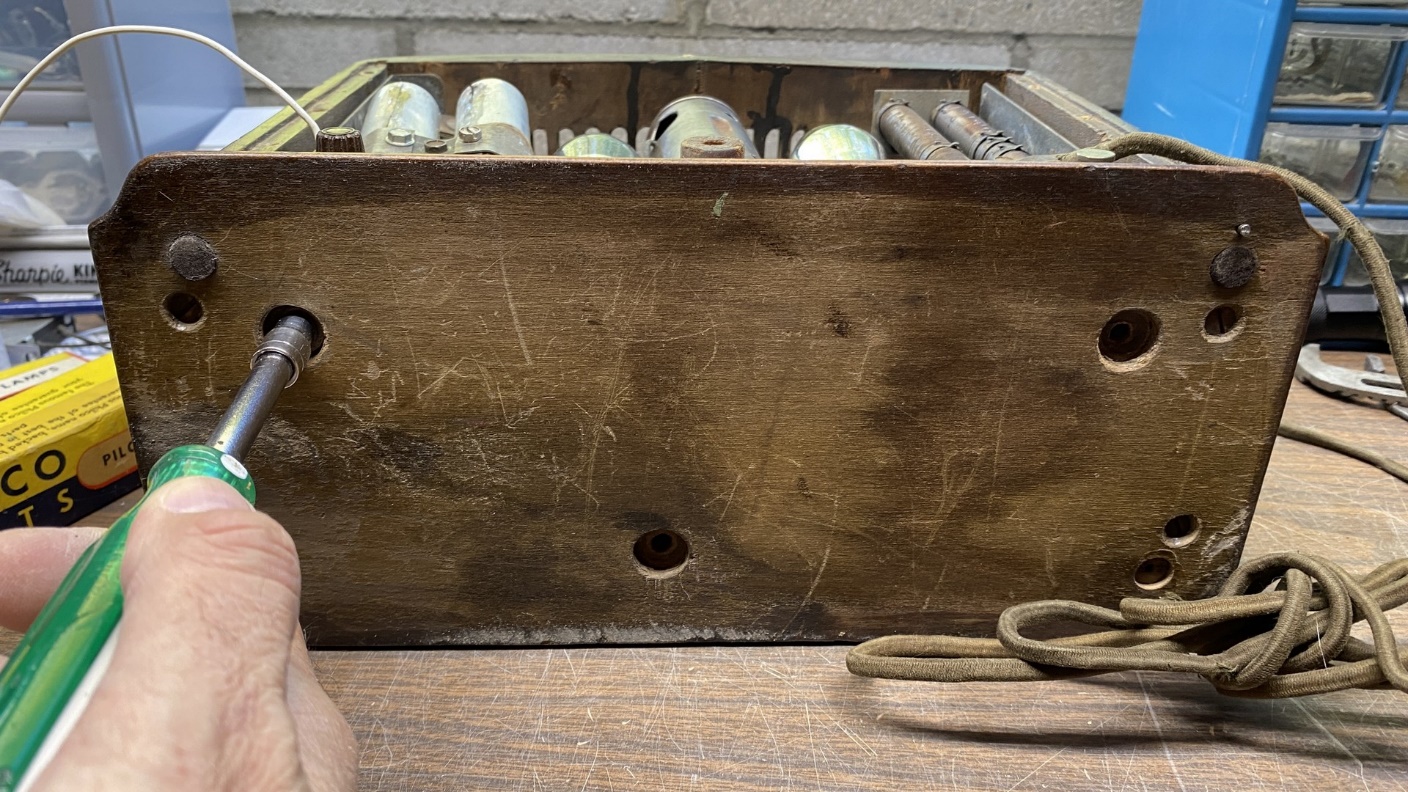
Removing the three chassis mounting screws.
Once the chassis mounting screws had been removed, the chassis could be slid out of the cabinet.
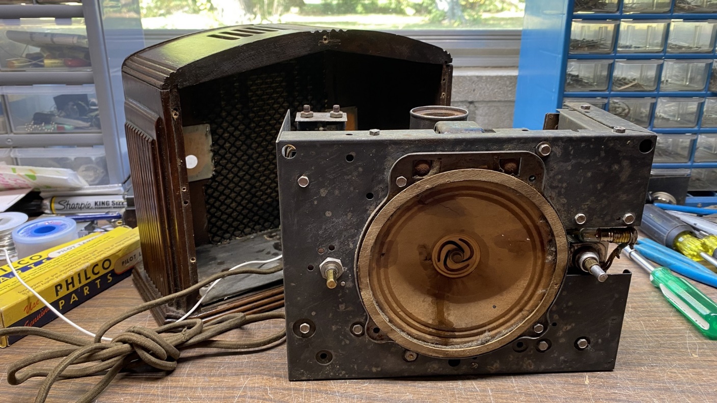
The 54 chassis is now removed from the cabinet.
I looked it over some more. The original speaker appeared to be in good shape – not perfect, mind you, but good. All tubes and tube shields were in place.
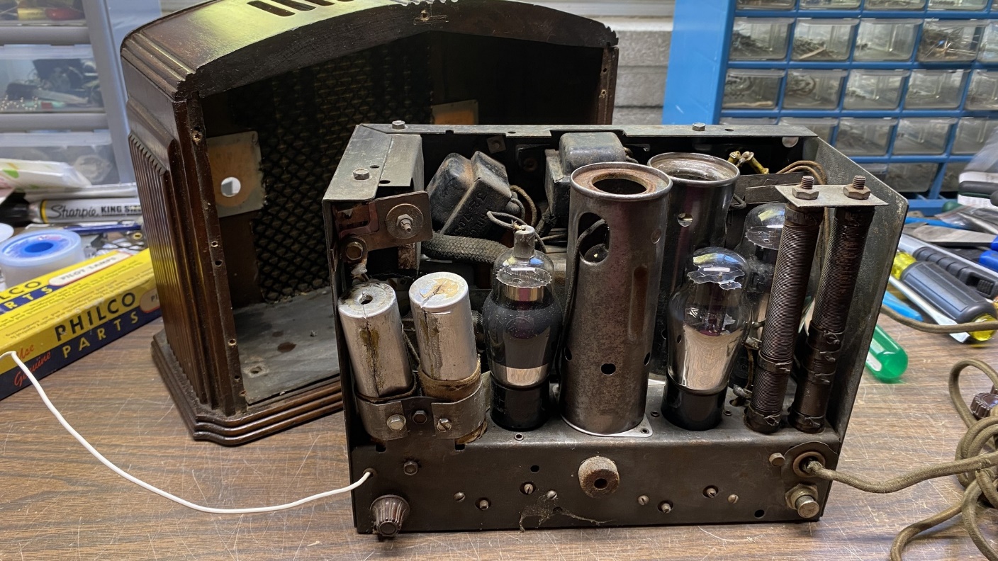
A back view of the chassis.
I had been told the radio was working and receiving stations, but I did not try it. It still had its original power cord, and I do not trust 88 year old power cords. In fact, I cut the cord, removed and set aside the round AC plug, and threw the cord away before I went any further.
Let’s discuss the plans I have for this radio.
I am going to remove all five of the standard base tubes and replace them with octal sockets from my parts stash. The two tall power resistors you can see in the photo above will be removed and will no longer be needed. I will use two metal tubes in this radio. As they will be metal, they will not require tube shields. The five tubes I will use will be smaller than the original standard base tubes, saving some space on top of the chassis. The elimination of the tube shields and the power resistors will also save space. As jam-packed as this chassis was originally, it will only benefit from any space which can be saved.
Please have a look at the new schematic below.
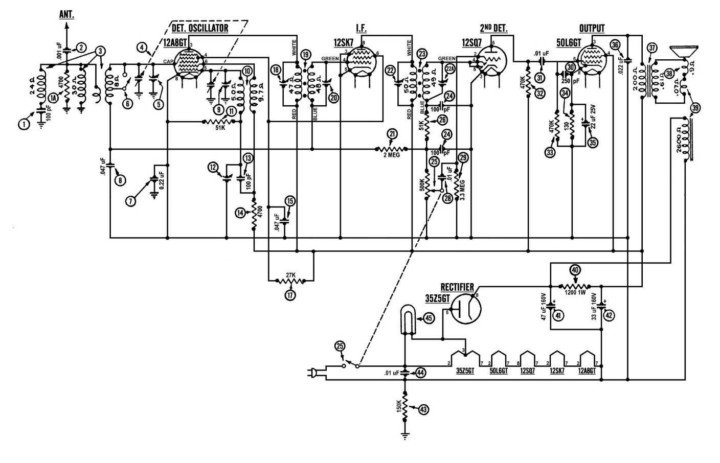
My modified model 54 schematic. Click here to see a larger version.
I took quite a bit of time developing a new schematic for this project, by studying other All-American Five (AA5) designs by Philco and other manufacturers. In fact, what you see above is the fourth version of the schematic. I have attempted to implement the best ideas I found in the other schematics I looked at while keeping the front end of the 54C basically stock.
If you compare this schematic to the factory Philco schematic (you can see a large version of the original here), you will notice several changes. Let’s discuss these.
The power supply has been greatly simplified. The bias network has been completely eliminated, as newer AA5 designs did not design their power supplies in this manner.
The power resistors have been totally eliminated. The sum of the five filament voltages adds up to 121 volts, so no dropping resistor is needed.
The filter choke, part (40) in the original schematic, has been replaced with a 1200 ohm, 1 watt resistor. This will free up more space on top of the chassis.
The 35Z5GT was designed with a tapped filament for easy use of a 6.3 volt dial lamp. You can see it in use in the new schematic.
I will be using the original speaker, and I am aware that its audio output transformer will not completely match the output impedance of the 50L6GT tube. The original 43 tube had a 3000 ohm output impedance; the 50L6 has a 2000 ohm impedance. I do not expect the slight mismatch to be a major issue.
Sime I am using the original speaker, it has a field coil. It is connected into the power supply in the same manner as the field coil in the Philco model 38-14. The field coil only serves to make the speaker operational and adds nothing to the power supply. In fact, if I wanted to use a permanent magnet (PM) speaker, I could do so and eliminate the field coil altogether.
The safety switch on the incoming AC line has been eliminated. Since this radio did not have its original metal back, I saw no point in keeping it.
A .01 microfarad AC safety capacitor (X1-Y2) has been added across the incoming AC line. A 150K resistor has also been added across the neutral side of the AC line and chassis ground.
The power switch has been moved from the neutral side of the line to the hot side for safety.
The radio originally used a large metal can which contained no less than six individual capacitors. This was part (7) on the original schematic and has been eliminated in the new design, replaced by a single capacitor which is labeled (7) on the new schematic.
Finally, I should mention that the neutral side of the AC line – which also serves as the B- line inside the radio – does not make contact with the metal chassis at any point, nor did it do so originally. Some radios were manufactured with what was known as “hot” chassis. These had one side of the line connected to the metal chassis. Philco, wisely, never made an AC-DC radio which was connected in this manner.
In the next installment, I will begin to disassemble this radio so that I can completely rebuild it to match the schematic I have drawn.
Until next time, stay tuned!