|
|
• DOERLE 2-TUBE RADIO • | |||||||||||||||||||||||||||||
| Appeared in "Antique Radio Classified",
October, 1994 Vol. 11, No.10 |
||||||||||||||||||||||||||||||
|
As a member of the
Antique Radio Club of Illinois, I became interested in the historical
aspects of the early days of commercial and shortwave broadcasting.
After reading articles in many of the 1930's radio books and magazines
of the era, I decided to try my hand at building a "home-brew"
radio. Vintage parts and junker sets are still available at hamfests,
swap meets and flea markets. Using original parts and hardware
for this project would be fun and give me a sense of what it was
like to build a regenerative tube radio from scratch.
Considering the age
of the parts needed was fifty to sixty years, finding all the
right parts was going to take time. It took over a year and a
dozen swap meets, auctions, hamfests to track down the parts.
Radio parts manufacturers like I.R.C., Cornell-Dublier, Carter,
Kurz-Kasch, Eby, Hammarlund, Pilot, National and Yaxley show the
variety of parts available sixty years ago. Some of the parts
needed restoring themselves in order to make the radio look "new".
Any corrosion or scratches would detract from the overall look
and feel of the set. I wanted to preserve the sense of artistry
and design that early builders used.
After looking through
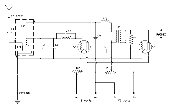
many reprints, I picked a 2-tube regenerative circuit popularized
by Walter C. Doerle in the early 1930's see Fig. 1. A combination of two of the designs in The Hammarlund
1937 Short Wave Manual, and additional information from two other
sources was used in the construction. Hints and tips on design
from the Short Wave Beginner's Book and coil designs from the
Short Wave Coil Data Book were also used. To simulate a vintage
radio buffs' search for parts where he could find them, I selected
many different parts' manufacturers (see parts list).

The two triode tubes
are used as a regenerative detector and an audio amplifier. I
wound a set of five plug-in coils covering the standard broadcast
band and the most popular international shortwave bands. Except
for some screws, the oak base and phenolic front panel, all the
parts are either used originals or new old-stock parts see
Fig. 2. The hook-up wire was even re-cycled from a vintage
tube tester chassis. During construction, I received valuable
information and tips from club members and friends.

After construction,
I attached the antenna, ground and battery wires to the set hoping
it would not melt down on the first try. Unfortunately, there
was only one small plume of smoke that rose from the regeneration
potentiometer. There was no damage to the set, however. After
correcting my error, I heard local AM stations coming through
loud and clear. Tuning was sharp and the sensitivity was much
better than I expected.
In the evening, distant
AM stations like KMOX in St. Louis and KOA in Denver were not
hard to pick up. The shortwave performance was surprisingly good
as well. Catching a dozen or more stations from around the world
wasn't more difficult than using a commercially built radio. Without
any dial calibrations to go by, searching for stations in the
shortwave bands gave me a feel for how it was done by early radio
experimenters. This radio has heightened my appreciation and enjoyment
of the hobby and I would encourage others to give it a try.
Doerle 2-Tube Regenerative Parts List
C1 - 140 pF. variable, BANDSET, Hammarlund MC-140-M
C2 - 35 pF. variable, BANDSPREAD, Hammarlund MC-35-S C3 - 100 pF. / 400 v. mica, Sangamo C4 - 35 pF. variable, ANT. COMP., Hammarlund HF-35 C5 - 250 pF. / 400 v. mica, Cornell-Dublier C6 - 0.1 uF. / 600 v. paper, Aerovox R1 - 3 Meg ohms, 1/2 w. carbon, Lynch R2 - 10 ohm rheostat, FIL ADJ, Amsco R3 - 50 K ohms, var., REGEN, IRC R4 - 200 K ohms, 1/2 w. carbon, IRC RFC - 2.5 uH. choke, National T1 - 10:1 audio transformer, Rauland R-13, "All-American" V1 - #30 triode, DETECTOR, Raytheon V2 - #30 triode, AUDIO AMPLIFIER, Raytheon PHONES - High impedance 3K ohms, Brandes "Superior Matched Tone" L1 | Hammarlund XP-53, 5-pin coil forms, 1-1/2" diam. L2 | 1/8" spacing between windings. L1 top, L2 middle, L3 bottom winding. L3 | See Coil Chart below. All coils #28 AWG.
List of References
The Hammarlund 1937 Short Wave Manual
Third Edition, Copyright 1935, Hammarlund Mfg. Co., Inc. Reprinted by Lindsay Publications Inc., Box 12, Bradley, Illinois 60915 Short Wave Beginner's Book Radio & Television, New York, N.Y., Copyright H. Gernsback, 1940 Reprinted by Lindsay Publications Inc., Box 12, Bradley, Illinois 60915 Short Wave Coil Data Book Radio Publications, New York, Copyright H. Gernsback, 1937 Reprinted by Lindsay Publications Inc., Box 12, Bradley, Illinois 60915
|
||||||||||||||||||||||||||||||


