

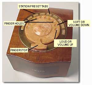
In the diagramed picture, the main parts of the Mystery Control box are indicated. The main dial has 10 finger holes, similar to an old-style telephone dial mechanism. These correspond to 8 station presets and two volume control functions; Loud and Soft as shown.
The fingerstop serves two purposes, one is to stop your finger travel around the dial when "dialing" and the second is to press it down in conjunction with the Loud and Soft voulme control functions.
Dialing "Loud" and pressing down the finger stop (or volume control lever) makes the Mystery Control send a continuous RF signal to keep the volume control motor in the radio turning to the desired loudness. Releasing the finger stop will halt the volume change. Dialing "Soft" and pressing down the finger stop keeps the volume control motor in the radio turning to your desided level. If you continue holding the finger stop down the motor will eventually click off the power switch, turning off the radio. The radio cannot be remotely turned on since the control frequency receiver in the set is also off.
Reprinted from How It Works, Special Section of Volume IX, Rider's Manual, Copyright 1938, John F. Rider
Philco Mystery Control
Several of the current Philco receivers employ a novel type of remote tuning called Mystery Control. These receivers can be tuned automatically to any one of eight stations, and the volume adjusted to any desired level, from a remote box which is about 6 by 8 by 4 in. This control box is entirely self contained; there are no wires to it from the receiver or from the power lines.
To tune a station (once the receiver is turned on manually, and the band switch set to "remote") it is only necessary to spin a telephone type dial to a stop and then release it. Within 15 seconds the receiver will retune itself to the station dialed. If the volume is too loud or too soft, soft and loud positions are provided on the dial. The set can also be turned off from the remote box.
Control Box
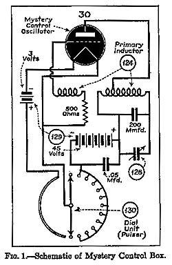
The control box is, essentially, a battery operated oscillator (Fig. 1). It is designed so that it is normally off and is turned on only during the dialing operations. The molded dial has ten positions; eight station and loud and soft volume positions. This dial is connected to a pulsing mechanism which times the return of the dial so that connection is made to the several dial points at regular intervals.
As soon as the dial is rotated the filament of the type 30 oscillator tube is connected to its supply. As the dial returns the oscillator grid return is connected, intermittently, to the filament. This will set up an oscillation or pulse in the primary inductor (Fig. 1) for each contact on the pulser mechanism. As the dial comes to rest it again disconnects the tube's filament supply. Thus, for any particular position dialed, a given number of pulses are radiated from the primary inductor (Fig. 1).
To increase volume, the position at the extreme right is dialed and the end stop depressed until the volume reaches the desired level. The dial returns to its original position and, as it does so, sets up two pulses in the primary inductor. Depressing the end stop keeps the oscillator functioning and maintains the signal in the primary inductor on the second pulse.
To reduce volume, the second position from the right is dialed and the end stop held depressed until the volume reaches the desired level. This maintains the signal in the primary inductor on the third pulse. If the end stop is held down for a longer period the set will turn itself off.
Control Amplifier
A large coil or loop is located at the bottom of the receiver cabinet (secondary inductor, Fig. 2). This coil is tuned to the frequency of the oscillator in the control box by means of a trimmer located inside a cylindrical cardboard box in one corner of the loop. This loop or secondary inductor acts as the antenna to receive the pulses from the primary inductor in the battery operated control box.
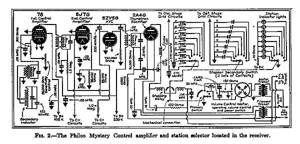
These pulses are amplified first by a type 78 and further by a 6J7G tube (Fig. 2). A 6ZY5G diode is used as avc tube to maintain an even input to the 2A4G thyratron rectifier output stage, throughout a wide range of signal strength. The second diode is used as a limiter to dampen strong peaks, which might cause the thyratron tube to continue firing over too long a period.
The output stage of the control amplifier is an argon-filled thyratron rectifier. This tube is similar to a conventional gas-filled rectifier into which a grid has been placed. A rectifier passes current during the entire portion of the a-c cycle in which the plate is positive with respect to the cathode. A grid inserted between the plate and the cathode would permit current flow only during that portion of the cycle in which the grid has the proper bias. If both grid and plate voltages are taken from the same a-c source their phase difference could be arranged so that the grid would permit current flow during the entire half cycle in which the plate is positive with respect to the cathode, so that no plate current would flow, or somewhere between these limits.
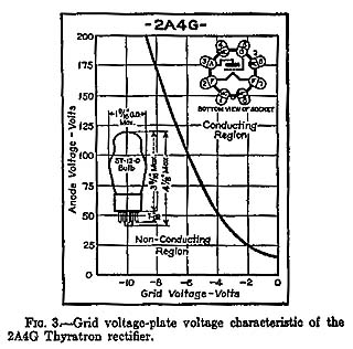 A type 2A4G thyratron rectifier is used in the Philco control amplifier. The characteristic curve of this tube is given in Fig. 3. Ratings and other characteristics follow:
Filament voltage . . . . . . . . . . 2.5 volts
Filament current . . . . . . . . . . 2.5 amps
Maximum anode voltage
Forward. . . . . . . . . . . . . . 200 volts
Inverse. . . . . . . . . . . . . . 200 volts
Maximum voltage between any
2 electrodes . . . . . . . . . . . 250 volts
Maximum anode current
Peak . . . . . . . . . . . . . . . 1.25 amp
Average. . . . . . . . . . . . . . 0.10 amp
Maximum averaging time . . . . . . . . 45 sec.
Tube voltage drop. . . . . . . . . . 15 volts
Cold starting time. . . . . . . . . . . 2 sec.
The grid bias for the 2A4G, used in the control amplifier (Fig. 2), is taken from the secondary of the tube's filament transformer. The plate supply is taken directly from the a-c lines. With the plate and grid voltages thus out of phase, no plate current will flow until the signal from the control amplifiers is sufficient to overcome the bias and supply the proper potential to fire the tube. Once operation has begun it is characteristic of this tube to continue firing throughout the remaining portion of the a-c cycle in which the plate is positive with respect to the cathode, regardless of any change in the grid voltage. The plate current of the 2A4G flows through and energizes the holding relay and permits operation of the stepping relay as discussed below.
Stepper Assembly
The stepper assembly houses a holding and a stepping relay. When the thyratron lights, the holding relay closes and the stepping relay pushes a ratchet as many times as the pulses sent out by the pulser in the control box.
There is a primary and a secondary ratchet. The stepper relay operates the primary ratchet which is connected to the primary switch. This switch controls the volume control motor and shorts the voice coil to ground in the station selecting positions. A muting switch, which connects the plates of the output tubes together is closed during the station selecting operation. The set, of course, is playing during changes in volume, but is muted as the secondary ratchet returns to its home position, and climbs to the station dialed.
The station selecting switch assembly is located beneath the chassis but is driven by the stepper assembly. There are three groups of contacts operated by the switch. One group switches the oscillator coils, the second group switches the antenna padding condensers and the third group of switches lights the pilot lamps indicating the station dialed.
Volume Control
The volume control and on-off switch are motor driven. The motor has an automatic clutch which releases and drops back as soon as the volume control is released by the stepper primary switch. This prevents over-shooting when changing volume and stops the gear train, which drives the volume control, immediately when the end stop is released on the control box. There is also a clutch in the volume control itself, so that the mechanism will not jam if the volume control lever is held down after the set is shut off.
The primary switch is a single-pole, double-throw switch which connects the desired winding in the volume control motor to increase or decrease volume. In parallel with this switch there is a single-pole, double-throw switch connected to the manual volume control. This switch is mounted directly below the receiver dial bezel.
Range
The normal range of the Mystery Control is within a circle of the receiver with a radius of about 25 feet. A sensitivity control is provided in the cathode of the 78 control amplifier, however, to fit a wide range of operating conditions. Normally, sufficient precautions are taken in the amplifier and remote control circuits to greatly reduce the possibility of electrical interference. There is little possibility of interference affecting the receivers if the sensitivity control is kept down to the first half of its total movement.
In some installations, however, owing to the presence of large metal objects around or near the receiver chassis, it will be necessary to increase the sensitivity of the control frequency amplifiers owing to the absorption of the metal surfaces. When this occurs, it will very likely be found that the same metal objects are shielding the receiver from excess static which would normally interfere with the control circuits in high setting of sensitivity control.
Control Frequencies
Mystery Control receivers are designed to operate on a control frequency somewhere between 350 and 400 kc. The purpose of a variety of control frequencies is to assure freedom from interference between the circuits of two sets operated in close proximity to each other. A 20 kc difference is recommended between control frequencies of sets that are operated in the same room.
In homes or apartment houses the distance between receivers will determine the difference in frequencies that is necessary. When the control frequencies are 10 kc apart, receivers will not interfere with each other so long as their remote control cabinet is kept a minimum of 10 feet away from the second receiver. By having the control frequencies differ by 20 kc, the second cabinet can be placed anywhere even on top of the first cabinet. The procedure for setting up stations on the Mystery Control receivers is similar to the procedure followed in setting up Philco electric-automatic tuning models. The eight stations, however, are automatically dialed by the remote unit instead of by push buttons.
