Philco 1937 Sub-chassis Servicing Tips
There
is a problem with most of the 1937 models using the separate RF sub-chassis construction. Philco called this new design "Unit Construction". The tunning gang, bandswitch and related RF components were built on a rubber
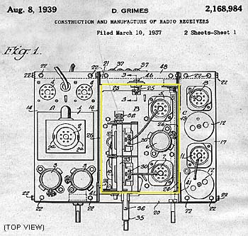
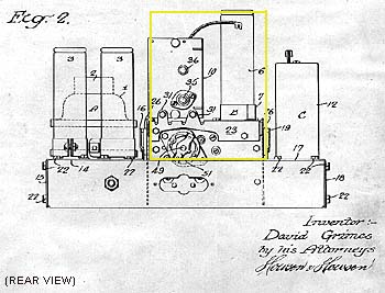
shock-mounted chassis. Most if not all of the bypass capacitors in this sub-chassis are buried underneath the riveted trimmer bank or the bandswitch section. This makes bypass capacitor replacement very difficult. See the two figures below from the original patent. The RF sub-chassis is outlined in yellow.
Make a very long loop tip from #14 gauge copper wire for the Weller soldering "gun" so you can get the tip way down into the tight spots. Even with this, you will need a glossary of profane language to get the job done! Use the long tip to un-solder leads to remove the sub-chassis for service work too.
By Doug Houston - (05/97, R+P Newsgroup message thread.)


