
RE-BUILDING WET TYPE ELECTROLYTIC CAPACITORS
Re-Capping Wet Aluminum Can Electrolytic Capacitors
by Patrick Lanigan
by Patrick Lanigan
 I recently started to restore a 37-650 Philco console radio at my son's request. The radio is his girlfriend's and had belonged to her grandmother. I have built some electronic equipment back in the 50's, two hi-fi amplifiers and a stereo amplifier from kits. I took up the challenge and spent hours on the internet accumulating information, tips and parts. I thought I would pass on some of the methods that I used to re-cap the electrolytics in the set as they will be applicable to all electrolytics in the older sets. If you are at all handy you will have all of the tools necessary to do the work without purchasing anything. The electrolytics in most sets contain at least one that houses two caps in a single can. This presents no problem but the multiple's require a little extra work on the base as you will see.
Some words of caution regarding the replacement of the electrolytics; always replace with equal or, preferably, exceed the working voltage of the cap being replaced, stay at or within 10% higher then the capacity rating of the cap being replaced (don't go lower) and observe proper polarity. All three are equally important.
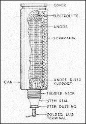
 The construction of the capacitor's can is an aluminum alloy which presents problems in soldering. The electrolyte used in most if not all of these capacitors was boric acid. For more information on the operation and structure of the electrolytics, see the Capacitor Book at www.faradnet.com. The information is actually more then you will need but very thorough. The cans are cylindrical and the single cap cans are stamped or spun in one piece from base to top. The top is usually crimped on and forms a vent to alleviate any pressure build up in the can. The multiple caps are stamped or spun in one piece from the top down and a bakelite or plastic base is crimped on the bottom. The can is vent on the top. In all instances the can is the negative terminal. On radios built prior to the fifties you will find that some of the caps have a cardboard insulator around the bottom where they pass through the chassis and under the mounting band. If you don't find any you may have a problem. These insulators are meant to keep the B- voltage on its own "floating" ground and not connected to the chassis ground. See article Those Pesky Negative-filtered Power Supplies, at www.Nostalgiaair.org. In the single cap the positive terminal comes out the bottom in the form of a rod that comes through the can base in an insulator sleeve and through a collar that is crimped tight around the insulated rod. In the multiples, the positive terminals come through the bakelite/plastic base via rivets that connect the grid in the can to the terminal lug on the outside.
The first step is to remove the cans from the chassis and saving the cardboard insulators and the ground terminal which is usually pressed between the side of the can and the insulator. The insulators can be removed by (again) gently twisting them around the can an applying pressure to move then down and off the can. Now you have to cut completely around the can about a half inch from the bottom. This can be done with a fine tooth hacksaw blade or a cutoff wheel on a rotary tool. The can is so thin that you don't need the hacksaw frame, just the blade will do. While it doesn't have to be an exact measurement you should be within an eight of an inch or you may have problems later on in stability and or visual effect. As you penetrate the can you may have some drainage of residual fluid so be prepared. The liquid is not a corrosive acid but I would not treat it casually either. After you have cut the can completely around you should be able to gently twist the base and dislodge the contents and the base from the can in one piece. Do not bend it or otherwise distort the center rod as you want the contents to remain attached to the base as you remove it. Regardless of whether you are working on a single or multiple cap, all the contents will come out in one piece. To get the multiple capacitance they tap the aluminum grid at various spots along the coil and brought out a lead to the base. Bear in mind that the center rod as well as the grid plate is made of pure grade aluminum and is brittle. The rod should not be bent as it has a nasty habit of fracturing when bent and straightened.
 Once the contents are out of the upper portion of the can be careful not to distort the can, it now has no support and is very thin aluminum that bends easily. One of the cans on my set had a "pinch" in it where an overzealous person tightened the mounting band by the foot pound. I found that if I slipped the can over and up the plastic pipe mentioned later while tapping the high spots on the outer surface lightly with a soft wood block the pinch came out. Once you have the base and contents out of the can of the single caps unwind the grid from the center rod until you are down to the rod itself and remove the grid coil from the rod by bending the grid back and forth a few times. The grid is riveted to the rod and you can also file off the rivet heads to remove the grid. At the points where the rivets are located on the rod, the rod is flattened to accommodate the rivet. You are dealing with pure grade aluminum here and it is soft and easily bent so be gentle! I chose a flat area about an inch above the base and drilled out the rivet using a #43 drill bit and then tapped the hole for a 4-40 machine screw so I would not need a nut. I cut the rod about a half inch above this point in case I striped the first hole there would be a back up point to attach to. If you don't have taps you can use a 7/64th. drill bit and use a 4-40 machine screw with a locking nut. The locking nut is a nut with a nylon or plastic insert which will prevent the nut from loosening once tightened. This will be the attachment point for a terminal lug to which you can solder the positive lead of the new cap. The next step is to drill a hole in the bottom of the can on the single cap base with a #31 or 7/64th. drill bit.
  Again, using a 4-40 machine screw and locking nut with a terminal lug to create an attachment point for the negative lead of the new cap. The hole should be drilled about half way between the center and outer edge of the base and the screw head on the outside and the terminal lug and nut on the inside of the base (See Figure #3).
On the multiple caps there is no center post, leads (usually formed as part of the grid) come down to the terminals on the inside of the base. After cutting the can and removing the base and contents I just cut them away from the base. I then drilled out the heads of the rivets through the base on both the inside and outside and, using a pin punch of the appropriate size, punched out the shaft of the rivets which will leave you with holes through the base which you drill out with the proper drill bit and use 4-40 machine screws and locking nuts but this time with terminal lugs on both sides of the base to make your internal connections to the new caps' positive leads and to have an external terminals for chassis wiring. If you should break the base while making the holes in the base, don't despair. I broke one and found that since it rests in the ring formed by the bottom half inch of the can you can easily epoxy it back together. At this point you should identify the different cap leads through the base by dabbing a little colored paint (I keep on hand different color nail polish which I purchase cheap at the dollar stores) on the terminals so you will be able to identify the Mfd value of the cap attached to each terminal from inside or outside. Be sure to color both the inside and outside of each terminal Since there is no metal base except for the remaining bottom of the can around the bakelite or plastic base, drill a hole using the #31drill bit or 7/64th. bit just inside the metal where it is pressed around the bakelite/plastic close enough, preferably right against it, so that when you place a 4-40 machine screw with the head on the outside through the hole the head rests on the metal. If you can't get that close you can place a washer under the screw head which should catch the metal rim but you must catch that metal. When you make this hole bear in mind that a nut (which is a larger diameter then the screw) will have to rest entirely inside the can ring on the inside of the base. On the inside of this screw you again use a terminal lug and lock nut to which you will solder all the negative leads from the new caps, no terminal lug on the outside (see Figure #4).
bottom of the can around the bakelite or plastic base, drill a hole using the #31drill bit or 7/64th. bit just inside the metal where it is pressed around the bakelite/plastic close enough, preferably right against it, so that when you place a 4-40 machine screw with the head on the outside through the hole the head rests on the metal. If you can't get that close you can place a washer under the screw head which should catch the metal rim but you must catch that metal. When you make this hole bear in mind that a nut (which is a larger diameter then the screw) will have to rest entirely inside the can ring on the inside of the base. On the inside of this screw you again use a terminal lug and lock nut to which you will solder all the negative leads from the new caps, no terminal lug on the outside (see Figure #4).
The next step is to cut a one inch in length piece of one-inch PVC water pipe or plastic electrical conduit (I found that the outside diameter of this pipe is almost exactly, if not exactly, the inside diameter of the cans) for each of the cans. Now cut out about a half inch of the circumference of the pipe so it is open on the side like a closed letter C. The opening gives you a little leeway in an otherwise snug fit and access after assembly but more importantly that opening is necessary as the nut for the ground on the multiples is right at the edge of the base. I found a problem with the pipe diameter on the multiple as the can was crimped above the bakelite or plastic base so while the upper can fit like a glove in the top, it would not fit in the base without squeezing it.  If you don't under cut the bottom quarter inch, when you squeeze it into the base, it will no longer fit snug to the can. Before cutting the half inch out of the circumference, I placed the piece of pipe for the multiple on a 1" sanding drum arbor and placed that in my drill press, turned it on and held a file against the outside of the pipe to undercut the pipe by about a sixteenth of and inch in and a quarter inch high to the reduced the diameter to fit the base. If you under cut too much don't worry. You will be epoxying the pipe to the base so it does not have to fit snug but you will have to center it on the base so it aligns with the can. The same could be done with an electric drill by using one of those hand drill stands to hold the drill. The sanding drum arbor is one of those with a rubber drum over which you place a tube shaped sandpaper and tighten a nut which expands the drum to hold the tube of sandpaper (see Figure #5).
If you don't under cut the bottom quarter inch, when you squeeze it into the base, it will no longer fit snug to the can. Before cutting the half inch out of the circumference, I placed the piece of pipe for the multiple on a 1" sanding drum arbor and placed that in my drill press, turned it on and held a file against the outside of the pipe to undercut the pipe by about a sixteenth of and inch in and a quarter inch high to the reduced the diameter to fit the base. If you under cut too much don't worry. You will be epoxying the pipe to the base so it does not have to fit snug but you will have to center it on the base so it aligns with the can. The same could be done with an electric drill by using one of those hand drill stands to hold the drill. The sanding drum arbor is one of those with a rubber drum over which you place a tube shaped sandpaper and tighten a nut which expands the drum to hold the tube of sandpaper (see Figure #5).
 You now can solder the caps on to the proper terminal lugs or wait until after the next step. On the bottom edge of the one inch plastic pipe (I say bottom because on the multiple, if you have undercut it, that's the bottom, on the others it doesn't matter) sections apply a layer of epoxy and place the pipe onto the base of the cap cans centering the opening in the side on the ground screw. After the epoxy has hardened you can solder in the new caps to the proper terminals, observing the proper polarity, and slip the top of the can over the top of the pipe and twist it down to the base. If you didn't get the cut around the can perfect, just rotate it until the edges match up to the irregularities.
If you are within the half inch area the mounting band will mask the seam and if the cap has an insulator, that will also mask the seam. Because of the length of the pipe and the snug fit you do not need to epoxy the top of the can to the pipe. There are three advantages of using the plastic pipe in the caps. You add some body to the can, it keeps the can straight and in the future, if you need to replace the caps, you loosen the mounting clamp and twist off the top of the cap without even having to turn over the chassis. On those caps that are insulated from the chassis the connection tothe can is accomplished by holding the truncated negative terminal lug (you can see the lug in the middle foreground, Figure #3) that came with the cap against the side and bottom of the can and slipping the insulator over it and the can. The insulator presses the lug against the side of the can thus gaining the electrical contact to the can and chassis wiring.
Electrolytic Cap Insulators
Missing the insulators or did they disintegrate upon removal? I had always thought, that if I could find a use for the cardboard tubes in the center of bathroom tissue rolls, I'd be a rich man. Alas, when I did find a use its limited to those who restore old radios. If you take a tube and cut of a piece about an inch and three eighths long then measure the circumference of the cap can and transfer that measurement to the piece of tube you will find that the tube is larger. Mark the start and end distance around the tube and cut out the excess. Take the can that you are making the insulator for and place the cut tube over it with about an eighth inch overhang on the bottom, place it under a water faucet and thoroughly wet it. The cardboard will be pliable now and you can close it up around the can so the ends meet (see Figure 5). Now round the bottom edge of the wet tubing over the end of the can, place two rubber bands around the tube and can and set in the furnace room to dry. After it is dry it should conform to the can and you can shellac it or leave it alone. You can glue it closed if you want but that's not necessary as it will be inside the mounting clamp on the chassis and the clamp will snug it up. Hey, aside from having to wait for the raw material to be available, who cares if you ruin a few before getting it right, they don't cost anything. Speaking of those clamps, just to be on the safe side I took black plastic electrical tape and pressed it onto the inner surface of the clamps then took a razor blade and cut off the excess. From the outside you cannot tell its there and it provides extra insulation. I did this only on the cans with the "floating" B- ground, don't do it on the grounded caps