[Contributed by Richard G. Hines]
All photos by Richard G. Hines © 2007 and are used with his permission.
Any Philco radio which uses the dual tuning knobs will benefit from a good cleaning and lubrication. The dial drive mechanism used in Models 116, 640, 643, 645, 650, 651, 655, 660 and 665 can be cleaned and restored to proper operation by following this procedure.
Tools you will need: Needle nose pliers, 1/4″ nutdriver, adjustable wrench, and screwdriver.
1) Remove dial scale.
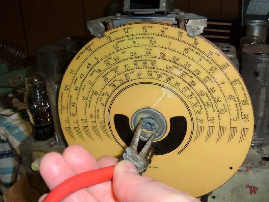
a) Insert needle nose pliers into the 2 holes of the sheet metal nut and turn 1/4 turn counterclockwise.
b) Lift off the dial scale and backing disc.
2) Remove the dial scale axle.

a) Rotate the ganged tuning capacitor to the fully open positon to access the setscrew on the semi-circular ring assembly. Loosen setscrew a couple of turns. No more to avoid retracting clear of the indexing hole in the main shaft.
b) Pull out the dial scale axle.

3) Remove the band select mask assembly.

a) Remove the screw that clamps the dial cord on the mask wheel.

b) On the band select actuator, push in the tensioner underneath to give enough slack so the dial cord can be slipped off the mask wheel.

c) Remove mounting screws on band select bracket and remove assembly.
4) Remove the shadow meter and dial pointer mask assembly.

a) Remove the 2 screws and set assembly aside, wiring and all.
5) Remove dial drive.
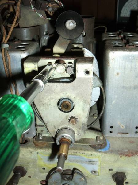
a) Remove the 3 mounting screws and work the assembly off the semi-circular ring.


b) Dial drive can now be taken off the bracket by removing the large hex nut.
6) Disassembly of dial drive

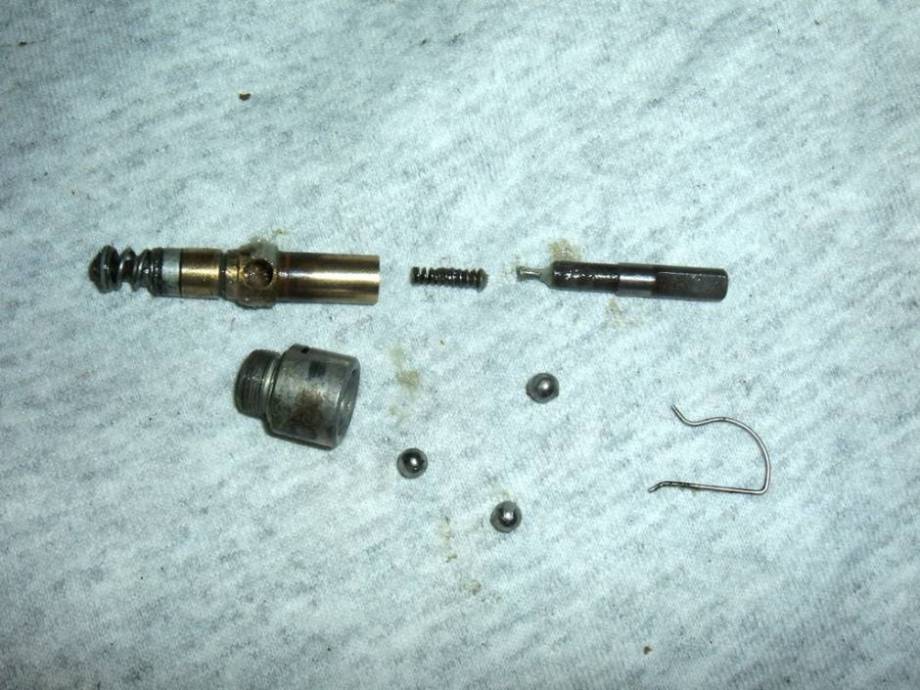
a) Work over a soft cloth so the ball bearings don’t scatter (3 total).
b) Pull off the retainer clip.
c) Push in on the fine tuning shaft to release tension on the ball bearings while pulling on the coarse tuning shaft. The innards pull free from the housing.
d) Degrease all the components, WD-40 works well. Relube with white lithium grease and reassemble.
e) This is a good time to lubricate the ganged tuning capacitor bearings and bushings with light oil. 3-in-One oil works well.
7) Mount the dial drive assembly.
a) Remount the dial drive on its bracket with large nut and lock washer.
b) Getting the dial drive to engage with the semi-circular ring can be tough. Put one mounting screw loose in the top left mounting hole to help hold the assembly and allow some freedom to postion it over the semi-circular ring. Use a screwdriver to pry open a gap to allow the semi-circular ring to be clamped between shaft and spring loaded washer of the dial drive. Install the other two mounting screws. Some positoning adjustment is possible to optimize the mating of dial drive and semi-circular ring. Tighten mounting screws and test the full range of motion of the ganged tuning capacitor. Re-adjust bracket and verify as needed to get smooth operation.
8) Mount the shadow meter and dial pointer mask assembly.
a) Mount the assembly with the 2 mounting screws.
9) Mount the band select mask and drive cord.

a) Mount the assembly. Install the band select drive cord and spring tensioner. Push in on the tensioner to allow enough slack to string the assembly. Adjust the postion of the mask wheel to concide with their corresponding bands.

b) Next install the dial cord clamp screw with flat washer. Gently tighten to hold the cord fast, no more. Note that the cord loops around the inside of the clamp screw.
10) Mount the dial scale assembly.
a) Insert the dial scale axle into the main shaft of the ganged tuning capacitor.

b) Install the small phenolic disc followed by the dial scale disc observing the indexing holes.

c) Install the sheet metal nut on the dial scale hub. 1/4 turn CW with needle nose pliers.

d) Fully open the ganged tuning capacitor. Rotate the dial scale so it’s positioned at the maximum frequency setting.
Tighten the setscrew on the semi-circular ring hub locking the dial scale in position.
Thanks to Richard G. Hines for sharing this with us.