Wrapping it all up.
It has taken a lot of work to get this model 65 to the point where it was now time to reinstall the chassis in the metal cabinet and finish up some things.
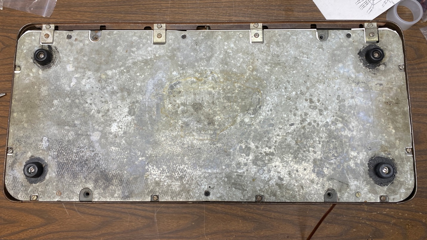
I began with the bottom cover.
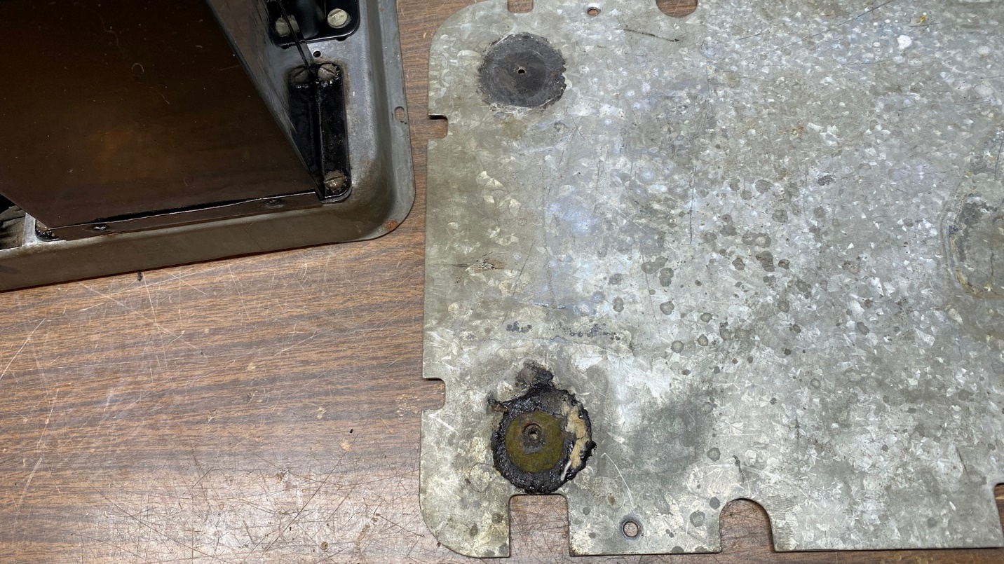
The original rubber feet had collapsed under the weight of the radio over the past several decades and turned to a semi-hard mush.
Knowing that mice had once used the bottom of this radio as an apartment, I took the bottom cover outside and disinfected it with Lysol Disinfecting Cleaner.
I sprayed Lysol liberally on the inside cover where the mice had been and waited 30 minutes as the directions called for. After the time had elapsed, I went back outside, wiped the cover dry with paper towels, and brought the cover back inside.
The old rubber feet had collapsed under the weight (around 50 lbs.) of the radio over the past 92 years. I removed the center screws and then began to scrape away as much of the old rubber as I could. I worked very carefully as I did not wish to cut myself with the razor blade. A better solution, I believe, would probably have been to use acetone to remove the old rubber residue.
Once I had removed as much of the old rubber as I could, I discovered that I had four rubber feet. I temporarily installed these in place of the original feet. I found that McMaster-Carr sells plastic feet (they call them bumpers), and I will be ordering some of these to use instead in the near future. Plastic should have an indefinite life whereas rubber will only meet the same fate as did the original feet.
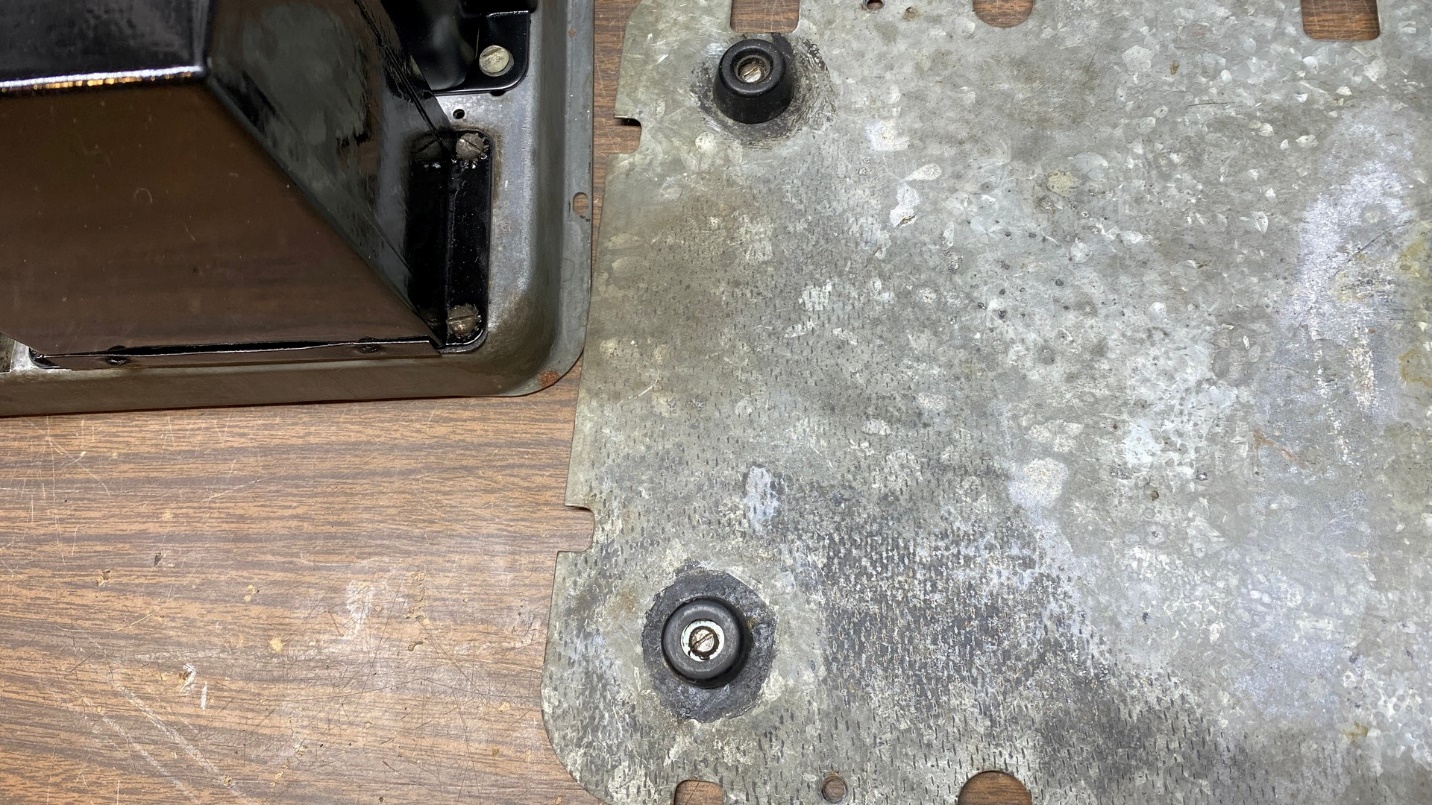
Four new rubber feet were temporarily put into place on the bottom cover.
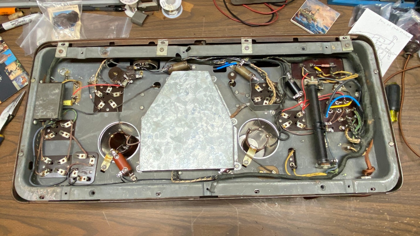
Now that I had new feet on the bottom cover, the next job was to reinstall the chassis into the metal cabinet.
Using the Lysol disinfecting cleaner again, I sprayed some on a paper towel and wiped off the inside of the metal cabinet. After this, I wiped the cabinet dry with a clean paper towel.
Now, with the chassis right side up, I carefully tilted the cabinet into place on the chassis, making sure to thread the AC cord through the hole in the back of the cabinet which was made for this purpose.
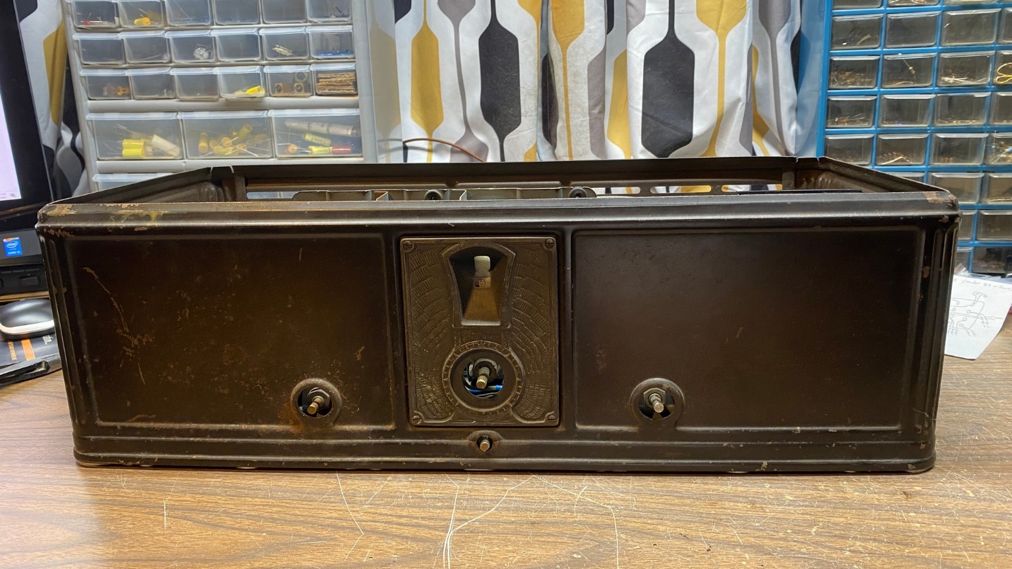
The metal cabinet is back in place over the chassis.
I slid one end of the unit over the edge of my workbench just enough that I could reach the two side screws from the bottom. These screws were installed and tightened. Afterward, I turned the cabinet around and set the opposite end over the edge of my workbench and repeated the procedure.
Now, with two screws installed on each end, I carefully lifted the unit, flipped it upside down, and set it down on my workbench. This was not an easy job since the radio was so heavy!
Chassis and cabinet after all mounting screws and brackets had been reinstalled.
Soon, I had all the mounting screws and brackets reinstalled and tightened.
I needed some new paper to replace the paper which the mice had chewed up. Having nothing else suitable, I ended up using a piece of U-Haul Wrapping Paper, which are large sheets of newsprint.
I did not consider this an ideal solution, but I had nothing else suitable around the house.
I took one sheet of the paper and folded it twice so that I had three thicknesses of the paper. I then placed the bottom cover over it and began to trace out the various holes, notches and curves it would need to have. Next, I temporarily set the bottom cover aside and went to work with a pair of scissors on the folded paper.
Before long, I had the following new insulating paper:
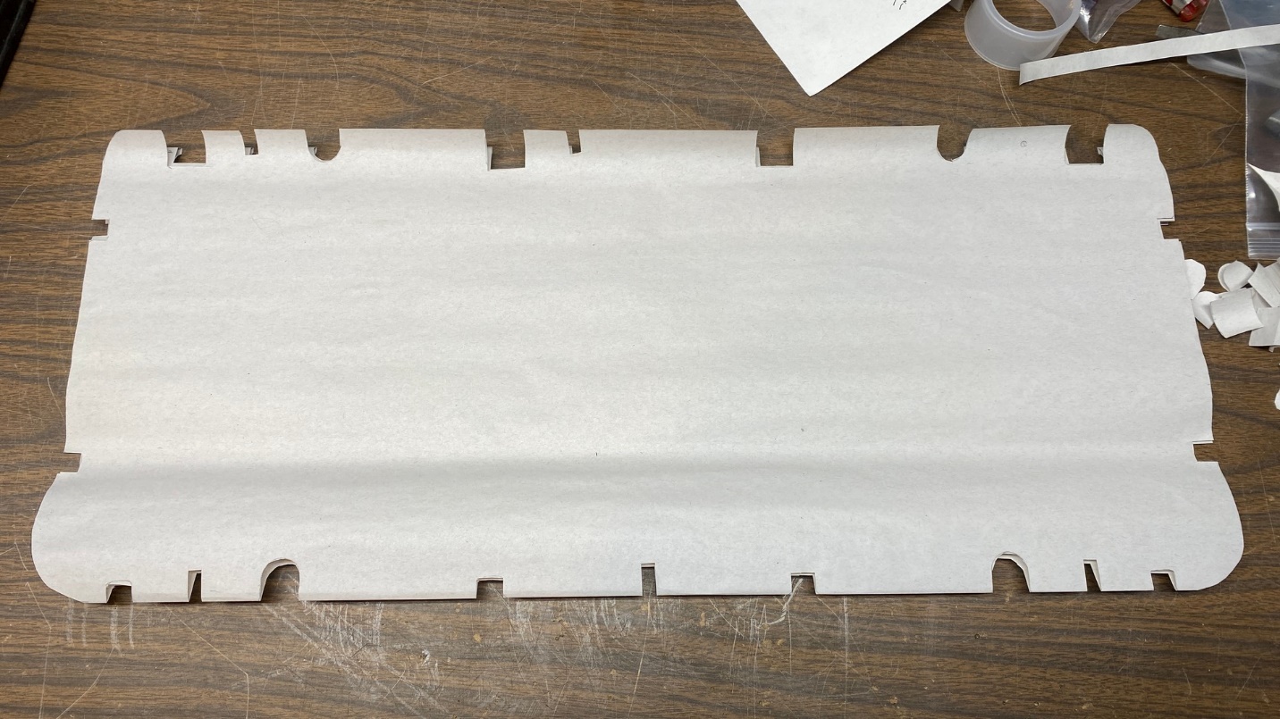
New paper to be used as insulation between the chassis and the metal bottom cover.
I then placed the paper on the bottom of the chassis.
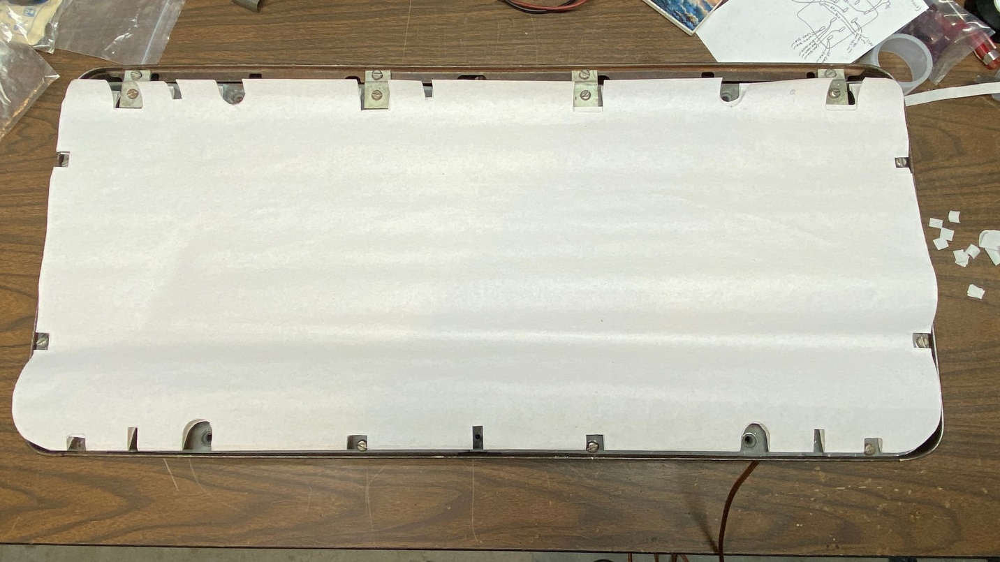
The new paper is now in place on the chassis.
Finally, the bottom cover was placed on top of the paper and chassis, and screwed into place.
The bottom cover is now back in place on the radio.
Very carefully, I flipped the radio right side up again and reinstalled the knobs.
The radio is almost finished now.
At this point I reinstalled the tubes. (I had temporarily removed them before I began to put the chassis and cabinet back together.)
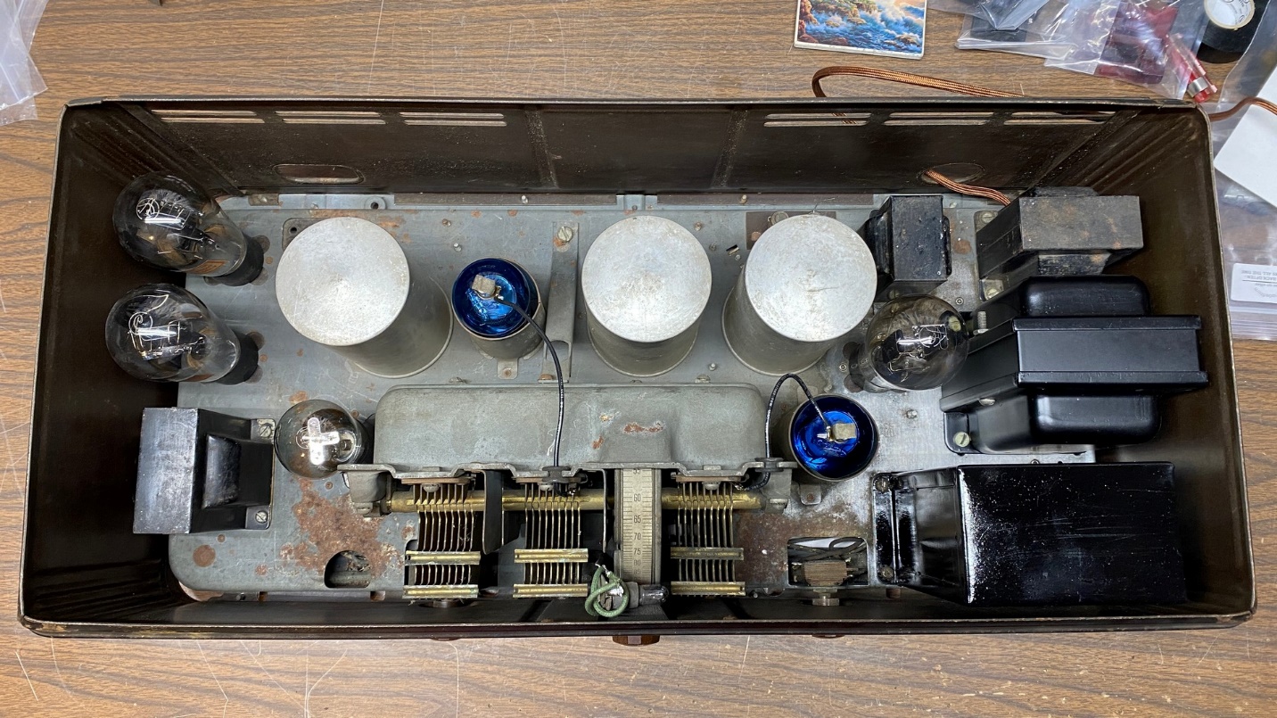
Tubes are back in place in the model 65. As you can see, the C-324 tubes have been replaced with Arcturus Blue 124s, and the C-327 was replaced with an RCA UY-227.
Finally, the metal lid was placed back on top of the cabinet.
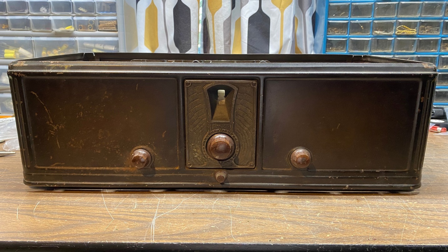
The Philco model 65 was now complete.
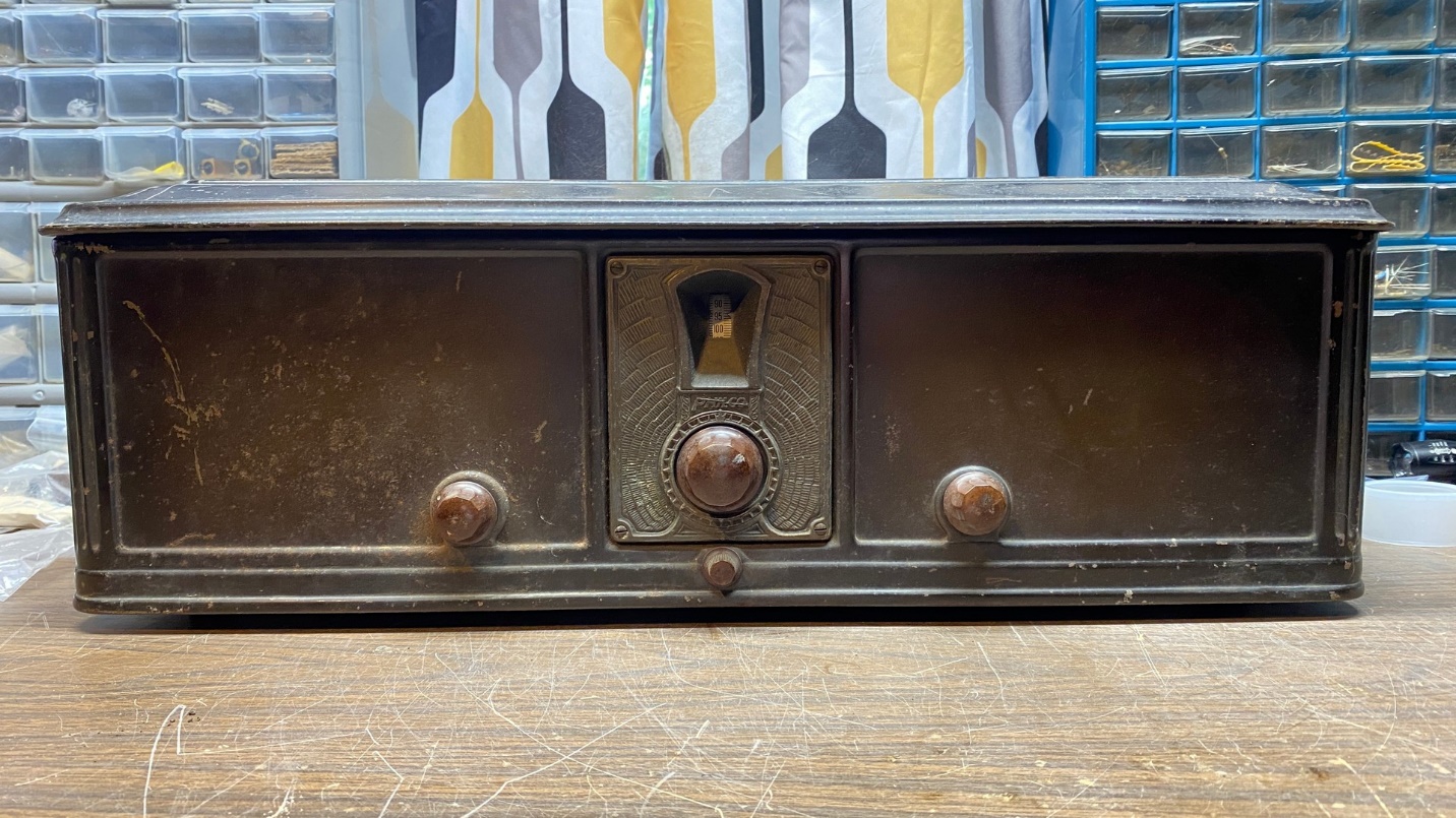
The finished product.
Yes, the cabinet has scuffs and scratches – but, again, it is 92 years old. I don’t think it looks too bad for its age.
I tried the radio out again with the Philco 87 speaker, this time temporarily removing the Arcturus 124s and the RCA 227 and replacing these with ST-type (taper top) 24As and a 27. The radio did not perform any better with the newer tubes, so the Arcturus and RCA tubes were reinstalled and left in place.
The Speaker
Actually, I have two F-10 speakers. One has its original grille cloth but is torn in many places; the other has cloth which is obviously a replacement.
When Debbie purchased the model 65 for me, it came with the speaker which has the replacement cloth.
Later on, I found, and purchased, this speaker which has original cloth, albeit in poor shape.
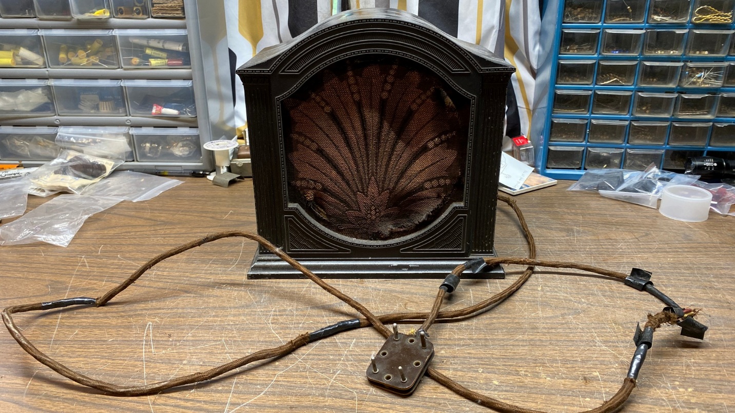
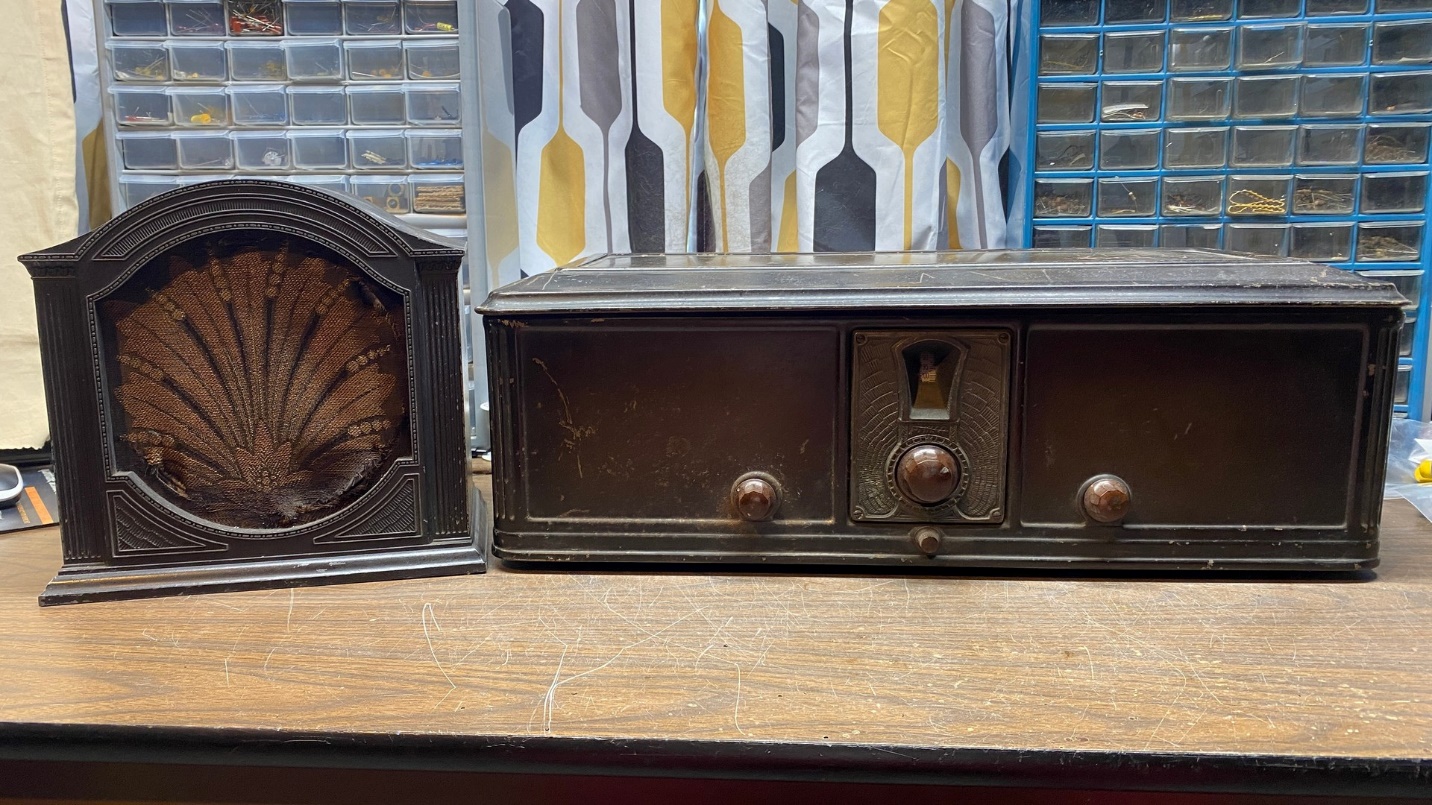
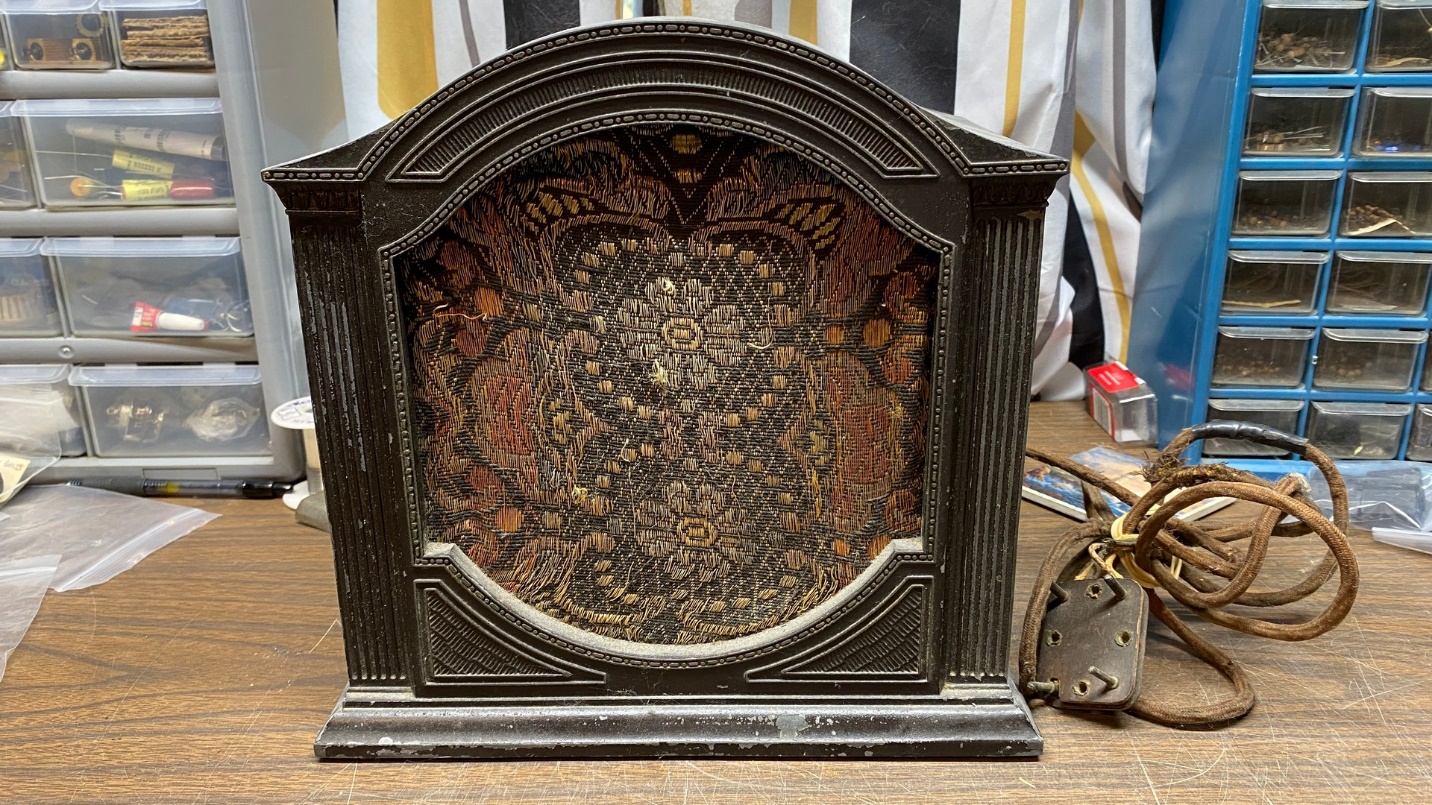
Model F-10 speaker for 1929 Philco table model radios.
As you can see above, the speaker cable was in rough shape and will need to be replaced.
If I can remove the original cloth without destroying it, I will attempt to use some Stitch Witchery in an attempt to fuse the torn pieces of fabric together. But that is a job for another time.
I tested this speaker out. It has an open field coil, and it appears one side of the audio output transformer primary is shorted out. Great.
So, I set that speaker aside and pulled out the other F-10 speaker, which originally came with the model 65 radio.
Another Philco F-10 speaker.
The speaker cable of this speaker was not in much better shape. When I tested the speaker, I found that this also had an open field coil – and an open audio output transformer primary.
Since both speakers have issues, both were put back into storage for now. I will decide which speaker to have fixed, and look into having that done, later on.

The 65 and its matching speaker do look well together.
Okay, folks. That is it for the Philco model 65 restoration. Thanks for following along.