I did not imagine this restoration series would end up taking up this many chapters, but this is the way it goes sometimes when I am trying to be as meticulous as I can in the restoration of a radio.
As I now had the replacement Solen Fast capacitors I needed, it was time to begin rebuilding the old Mershon electrolytic capacitor cans.
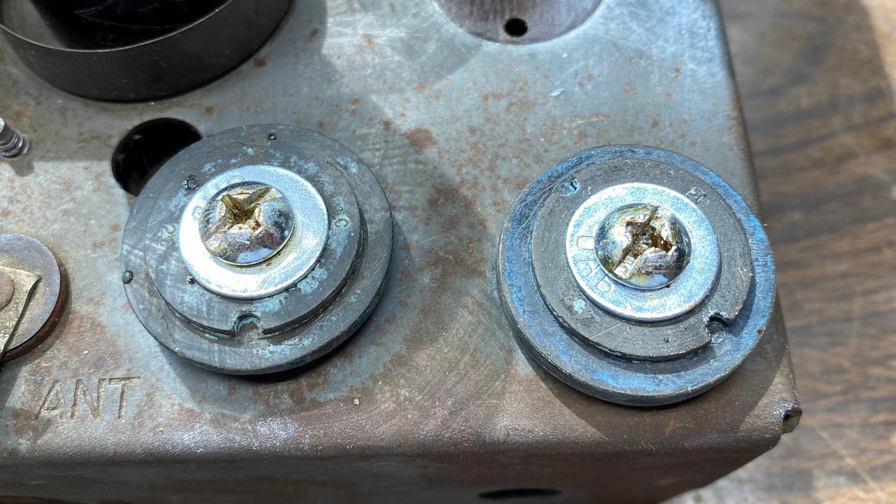
I had tried to get the insides of each can clean, but both have a very stubborn layer of bluish-green residue, likely the result of the reaction of the boric acid solution originally used as an electrolyte in these capacitors with the copper bodies of these units.
I decided that I would solder the negative leads of each capacitor to the copper cans, on the inside of each. Therefore, I sanded down two spots, one inside each can, until I had two bright copper spots inside each one. I planned to solder a wire to the sanded-down spot in each can. This wire would then connect to what would become the negative lead of the replacement capacitor.
The two Mershon cans with new wires soldered inside each copper shell.
Once a wire had been soldered inside each can, the cans were set aside temporarily.
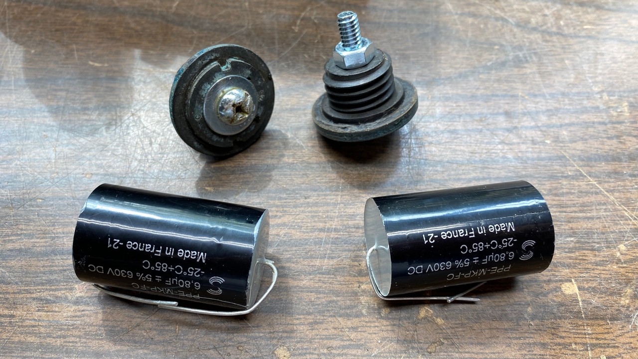
A quick trip to the local hardware store yielded the new screws, flatwashers, and nuts I needed for this project. The original positive studs of these Mershon capacitors used a ¼” threaded aluminum end. One nut held the positive electrode in place on the bakelite base of the capacitor. A piece of metal, bent into an L-shape, served as the positive terminal. This in turn was held on with a second nut. The L-shaped piece of metal was thus wedged between the two nuts.
We are going to replicate these positive terminals, only we are going to use ¼-20 steel screws, 1-1/2 inches in length, with a flatwasher and two steel ¼-20 nuts for each positive terminal.
The parts needed for the bases of each electrolytic capacitor.
The new screw goes through the top of the bakelite base. A 1-1/2 inch length was chosen so the new terminal would be approximately the same length of the original aluminum studs, and allow for plenty of room for two nuts and the L-shaped metal piece.
I placed one of the screws through a flatwasher, and then passed this through one of the bakelite bases. The threaded end of the screw goes through to the threaded end of the bakelite base, which is the bottom of this part.
One nut was then put into place, and the assembly was tightened together. You want to get the screw and nut tight, but not so tight that you risk breaking the bakelite base.
The process was repeated for the other bakelite base.
Assembled bottom pieces (base assemblies) of the electrolytic capacitors.
You may see how these assemblies looked in the photo above.
The next step was to pre-tin the heads of each screw. The reason for doing this is the simple fact that the positive terminal of each new capacitor will be soldered to the head of each new screw, within the large slot of each screw.
After the screw heads were tinned, excess solder was removed from each with desoldering braid.
While the parts were hot, the screw and nut was retightened to ensure these were as tight as possible without overdoing it.
The screw heads of each new screw were tinned with solder, and then the excess solder was removed.
Now, it was time to get out two new Solen Fast 6.8 uF, 630 volt film capacitors.
New Solen Fast capacitors with the capacitor base assemblies.
It should be noted that since these new capacitors are film capacitors, they have no polarity. For this reason, it does not matter which end you choose to make the positive terminal, and which you make the negative.
Once one end is soldered to a screw head, that end automatically becomes the new positive lead. The other end will be the negative lead.
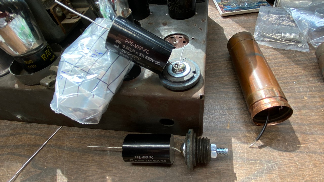
Preparing to solder one lead of a new Solen Fast capacitor to one of the screw heads in a base assembly. The other Solen capacitor has already been soldered to the other screw in the other assembly.
When I soldered these leads onto the screw heads, I placed the capacitor lead on the screw head as shown above. I had previously bent the capacitor’s lead wire and cut it to the necessary length. After I applied solder, and while holding the soldering gun on the screw head, I carefully grabbed the capacitor by its body and rotated it to a vertical position. I then removed the soldering gun, and held the capacitor in this vertical position until the solder had cooled sufficiently to let it go.
After the leads of one end of each capacitor has been soldered to the screw head of the base assembly, I added some hot glue over and around the positive side of the assembly, on the side which would be placed inside the copper can. This was done to ensure the positive end was sufficiently insulated from the outer copper can, which will also serve as the negative terminal of the capacitor.
It was now time to take care of the negative lead.
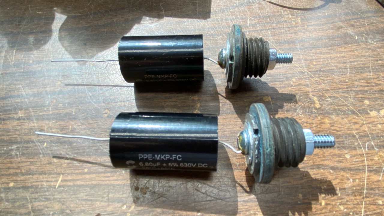
Both new capacitors have been soldered to the screw heads of the base assembly. These are the positive terminals.
Do you remember those wires which I soldered to the insides of each of the copper Mershon cans? It was now time to utilize the other ends of each of those wires.
I had previously cut those wires to a long enough length that there would be plenty of slack in each one, so it would be easy to solder each one to the end of each capacitor which would become the negative terminal.
The photo below shows how one of these was soldered together.
The negative wire was soldered to the opposite end of the new capacitor.
I repeated the process for the other capacitor. When both had their negative wires soldered to the negative lead I had added to each can, both new capacitors, along with the base assemblies, were pushed into the bottom of each Mershon can.
I used J-B Weld to hold the base assemblies inside each can. I also took the two bottom lips of each can I had previously cut off, and spot glued them to the bottom. Painter’s tape was applied to each can to hold everything in place while the glue dried overnight.
Painter’s tape is holding everything together while the glue dries.
The next morning, I went back to the basement and removed the tape from both Mershon cans. Everything looked well. I then went around about half of the bottom at the cut seam where the lip met the bottom of the can, and applied solder to the seam. I repeated the process on the other can.
After the solder cooled, I filed off the excess solder and smoothed off the seams to the best of my ability. The results may be seen below.
Rebuilt Mershon capacitors with their bottom lips soldered to the bottoms of each can.
I only went around about half of each seam as I did not want the solder to show on the sides which would be facing away from the chassis once the capacitors were mounted on the chassis. As you can see above, one of the seams turned out really well and I could have gone all the way around this one with solder and it would have looked fine. The other one turned out rougher, but it will function just fine when installed.
I checked each can with the capacity function of my digital multimeter. Both cans read 6.85 uF from the center (positive) stud to the bottom lip of each can, just as they should have. Electrically, these cans were finished and would function as the originals once did.
Finally, it was time to polish each can so they would look exceptionally well when mounted on the chassis. I decided to try an experiment, and used Mothers Mag & Aluminum Polish (my usual go-to ptoduct for polishing metals) on one can while I used old formula Brasso on the other.
Brasso used to be a very good product. However, several years ago, the manufacturer changed to a more green-friendly formula. The product is no longer as good as it once was as a result. I had purchased a small, older stock can of Brasso from a Canadian seller around the time the formula was changed.
Both Mershon cans had two very dark horizontal lines across each one on the sides. The Mothers polish did basically nothing to remove these lines, while the Brasso removed most of the lines. Overall, however, I feel that Mothers did the best job of polishing the can.
Yes, Mothers is designed for aluminum, but is a very good cleaner and polish for all metals.
One Mershon can was polished with Mothers while the other was polished with Brasso.
The only thing that remains to be done to these cans now is to spray each one with a couple protective coats of clear lacquer, so the cans retain that freshly polished look for several years. At the time I write this, it is raining, so that job will have to wait for another day. Once the cans are sprayed and they have had a chance to dry, they will be mounted on the chassis and connected into the Philco 90’s power supply circuitry.
This chapter has been longer than normal, but I wanted to show you in detail how I rebuild these old Mershon capacitor cans. The new Solen Fast film capacitors should have a virtually indefinite life, compared to the typical lifespan of electrolytic capacitors which is typically 20 to 30 years, depending on how much use it sees daily.
I hope to wrap everything up with this Philco 90 in the next part of this series. Please stay tuned.