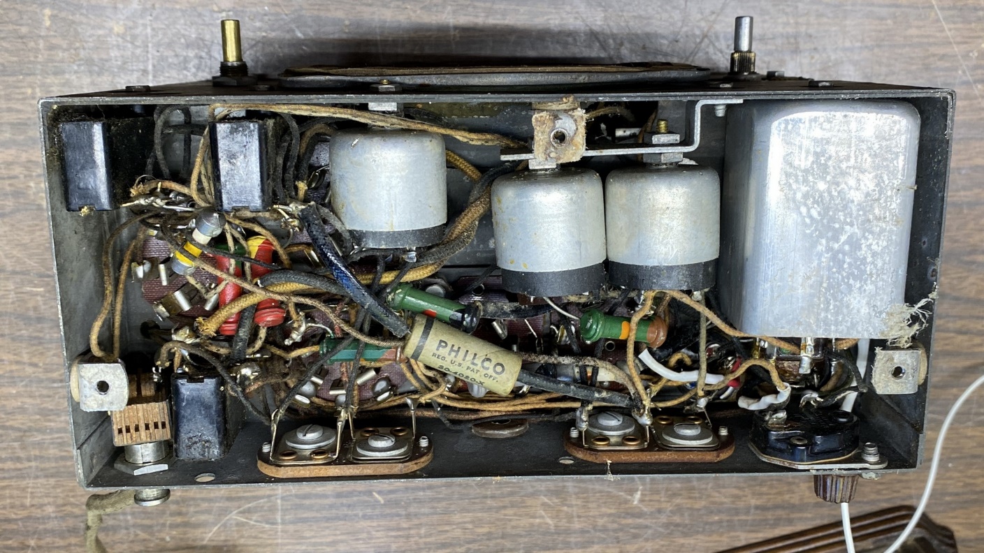
The radio is small, but the project is going to be big. If you don’t believe me, take a look at the underside of the chassis above. Philco really packed a lot into that cramped chassis in 1933. The task I have set for myself is to completely disassemble this chassis, down to bare metal, and then completely rebuild it, going by my modified model 54 schematic.
So, without further ado, let’s go!
I began by removing the two tube shields and the five tubes. This seems like a very simple procedure, and normally it is. However, I ran into a little trouble at the 75 tube.
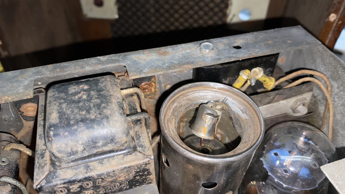
Things did not go as planned when I attempted to remove the grid connector from the 75 tube.
Let’s take a closer look at that.
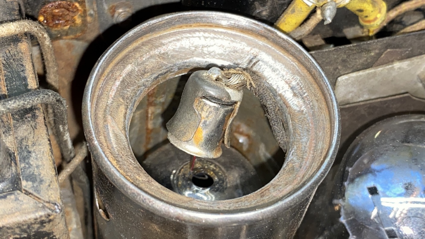
The 75 tube is broken at the top.
Yes, instead of the grid connector coming off the 75 grid cap as it should have, it pulled the grid cap with it. This in itself is not unusual; I have often attempted to remove a grid connector from an old tube only to remove the grid cap with the connector, leaving a bare wire protruding from the glass at the top of the tube. But this is the first time the glass has broken at the bottom of the grid cap!
Oh well, I guess I didn’t need that 75 tube anyway. I would not have reused it in this radio, but it would have been nice to have it in my tube stash if it had been good. One thing is for certain – it is no good now, and it was therefore given a decent burial in my wastebasket.
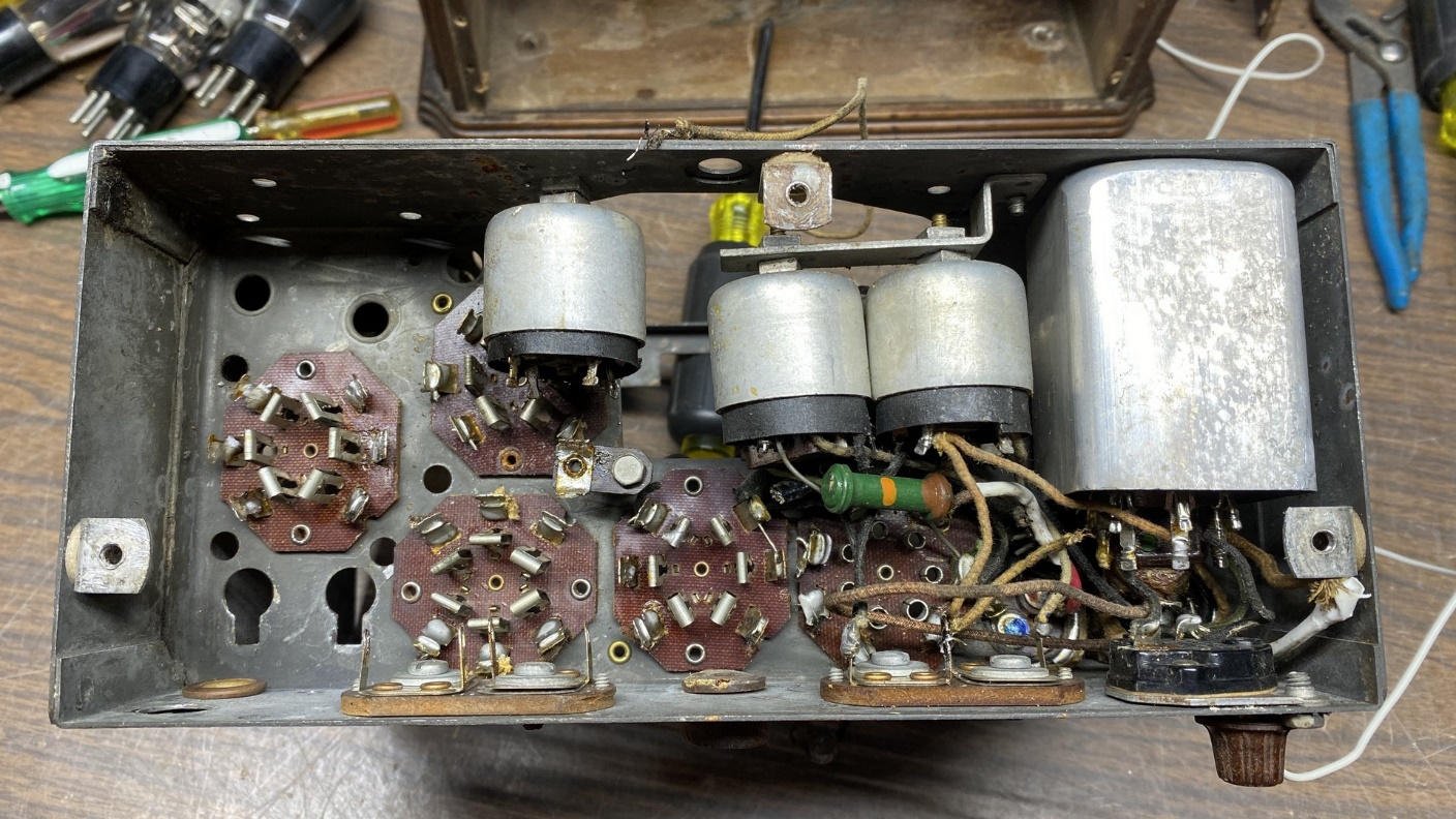
Once the tubes were removed, the chassis looked like this.
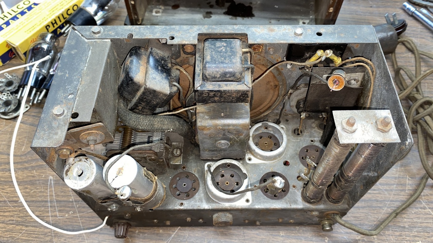
Philco model 54 chassis with all tubes removed.
Now it was time to start removing parts. Before I did that, however, I realized that I would need something to go by later on so that I would know how to reconnect the various coils and IF transformers.
After spending some time with my favorite graphics program on the computer and studying the underside of the 54 chassis, I came up with this:
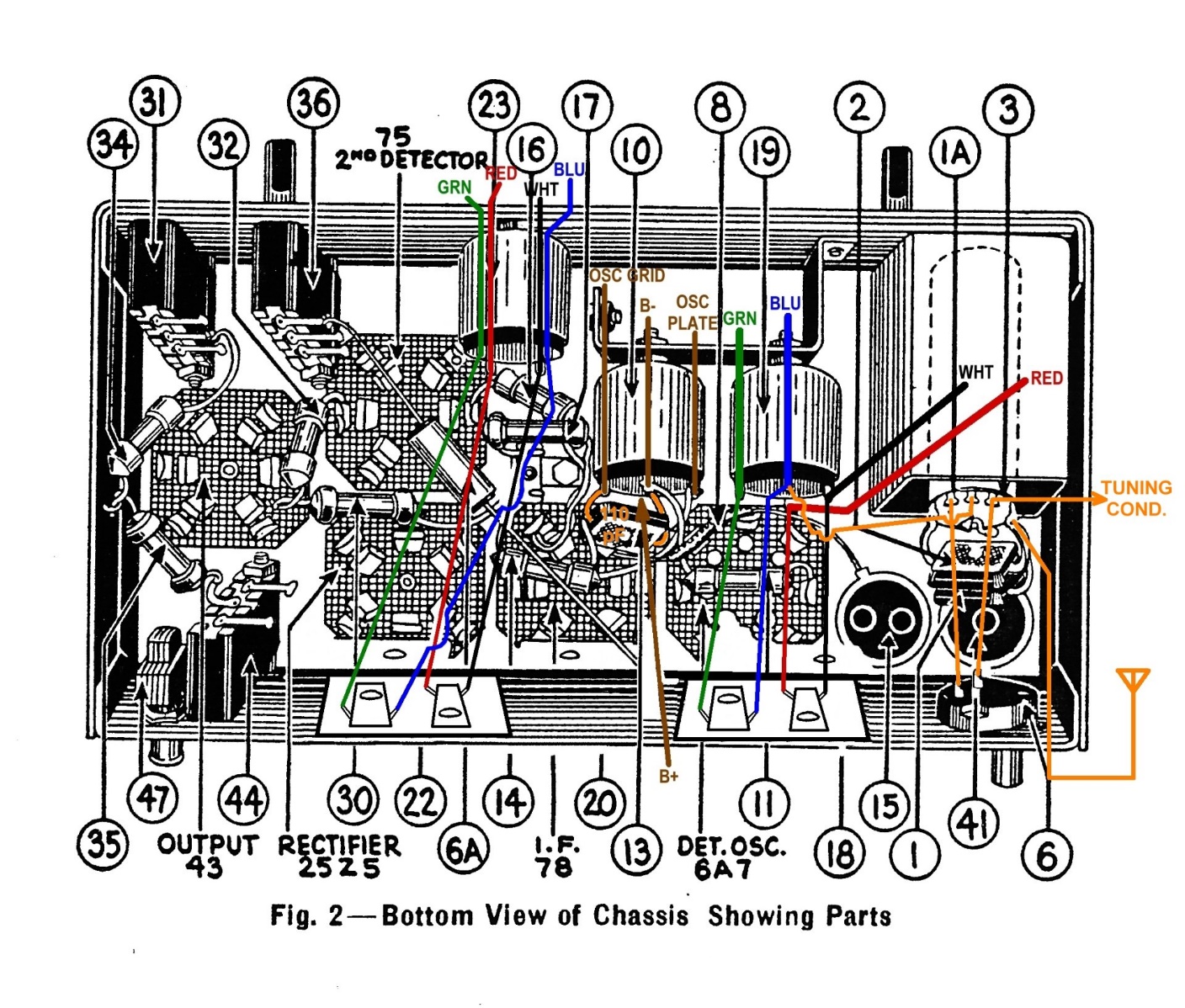
A diagram showing how to reconnect the coils and IF transformers.
I also noticed a discrepancy between the Philco service information and this radio. The Philco service data shows three IF trimmers. This radio has four, and they are made quite differently from what is shown in the Philco data. I made note of these in my drawing above, showing how each one connects to the two IF transformers.
Once that chore was finished, I began to remove parts from the chassis.
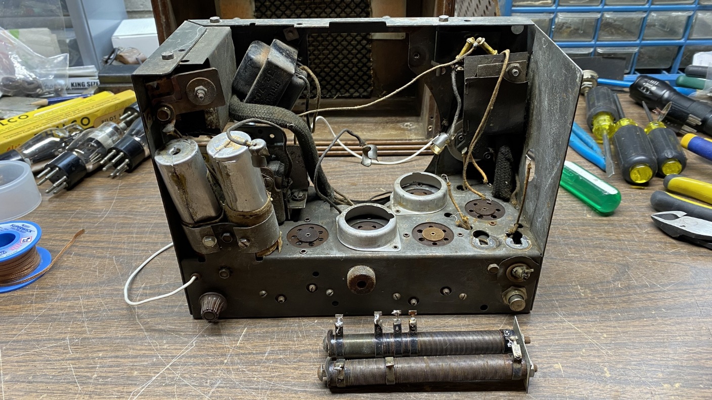
After removing the speaker, the two tall power resistors were disconnected and removed.
I removed the speaker and put it in a safe place so its cone would not be damaged. Then, I removed the two large power resistors from the top of the chassis. Those resistors will no longer be needed with the modifications I plan to implement. Their omission will eliminate a source of heat as well as removing an unsafe condition from the radio (the exposed terminals on the resistors). Keep in mind that I will not be reusing that homemade cabinet back when I am finished.
I then turned the chassis upside down and began removing parts underneath, starting at the audio output tube and working towards the set’s antenna coil.
I begin to remove parts from under the chassis.
Returning to the topside of the chassis, I began to remove parts here as well.
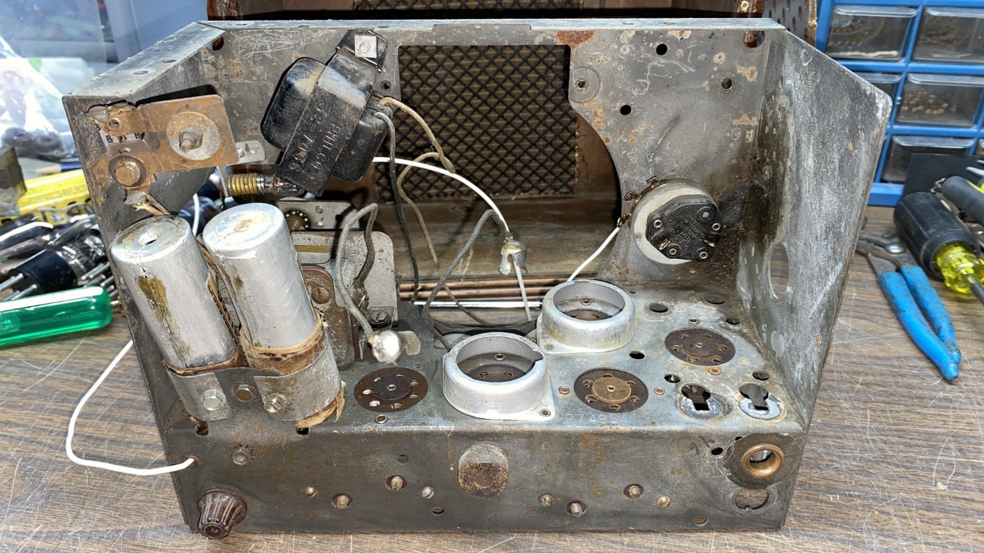
Parts are also removed from the top of the chassis.
It did not take long to remove almost everything here, as seen below.
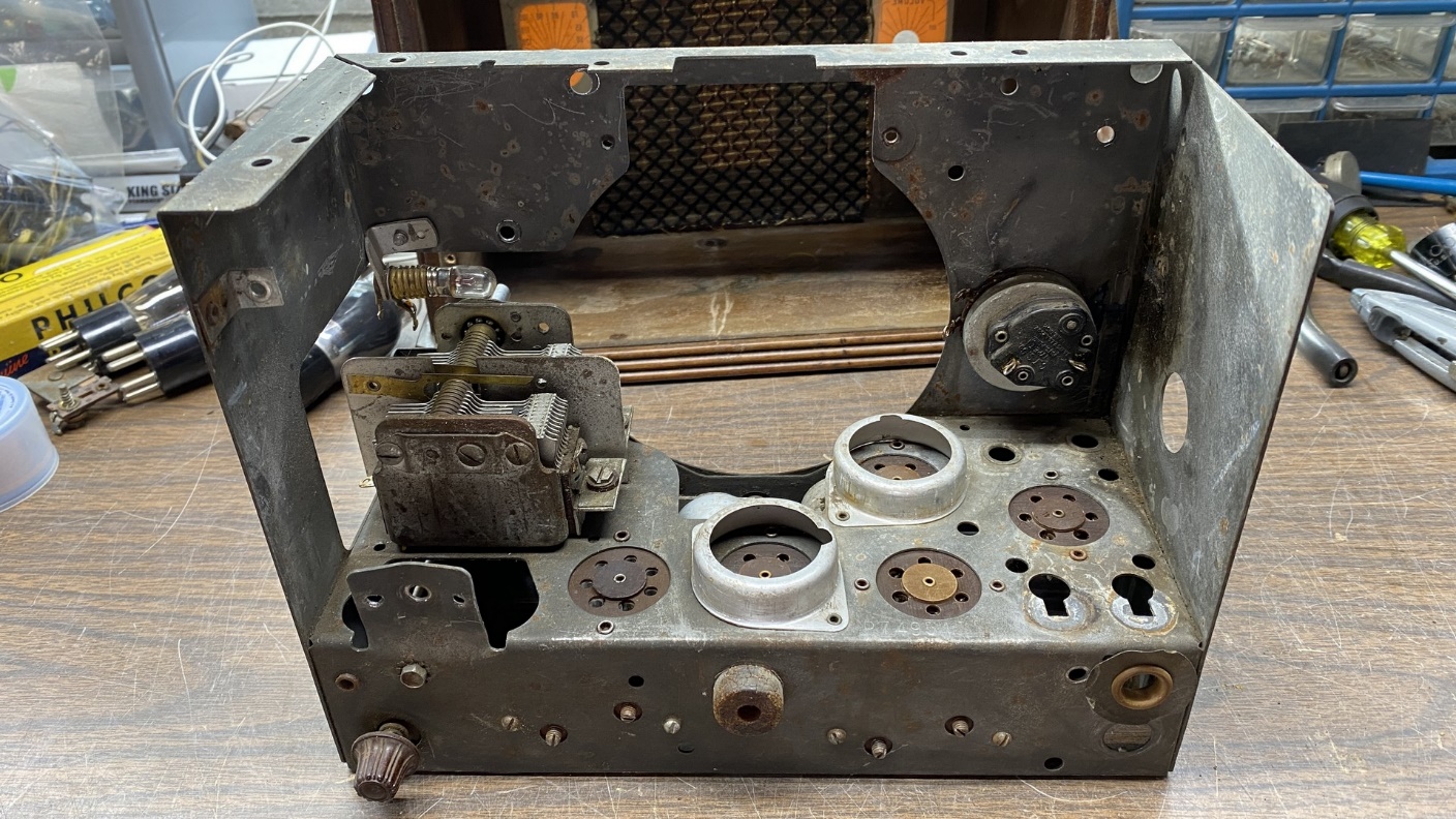
Now, only the tuning condenser, dial lamp assembly, and off-on-volume control remain topside.
Returning to the bottom of the chassis, I soon had everything removed save for the IF transformers, the oscillator coil, the IF trimmer assemblies, and the band switch.
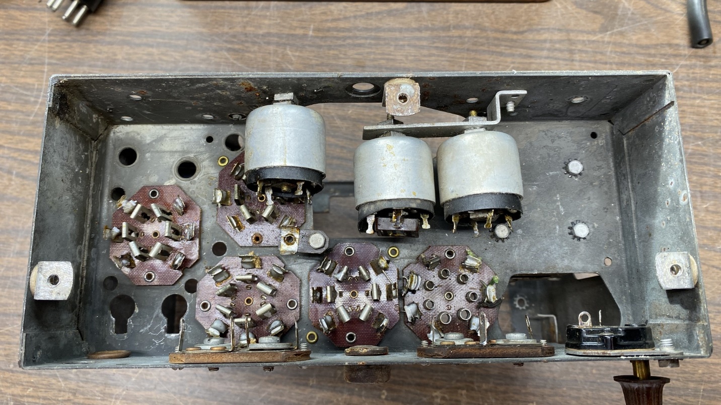
Hardly anything is left underneath as well.
The radio chassis has almost been completely stripped down at this point, but a bit more remains to be done before I can begin to rebuild the radio. In the next installment, I will remove a few more things and then start to build a practically new radio from the bare chassis on up. Please join me then.