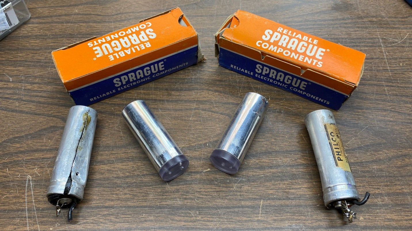
New replacement aluminum cans, which had originally been a pair of Sprague Twist-Lok electrolytic capacitors, had arrived by now and it was time to prepare these for use in my Philco model 54 radio chassis. The photo above compares the new cans with the originals.
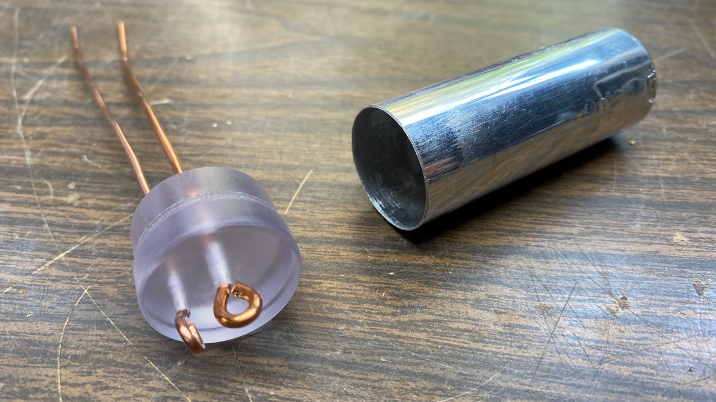
One of the new cans with plastic plug removed. New terminals were made from electrical wire.
Holes had been drilled in the plastic caps of the new capacitor cans to allow me to insert pieces of solid copper electrical wire. I ended up using 12 gauge wire for the positive terminals, and 14 gauge wire for the negative terminals.
For the bottom (terminal) side, I formed the wires into loops. I acquired the idea to do this after seeing this post on the Philco Phorum.
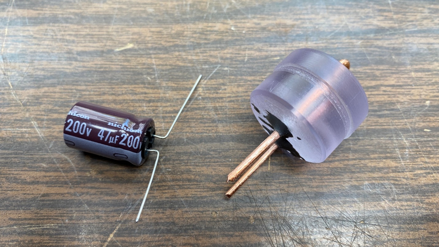
The wires were glued on the top side of the plastic plug to hold them in place. A new Nichicon electrolytic is ready to be attached to the wires.
At first, I tried to glue the wires to the top (can side) of the plastic cap with J-B Kwik. However, this did not hold the wires to the plastic adequately. So, I tried again with full strength J-B Weld. This required that I set the parts aside for 24 hours to allow the epoxy to completely dry.
The next day, I took the parts back to the workbench and began to prepare them for use.
I had some Nichicon 47 uF, 200 volt electrolytics on hand, as well as some 33 uF, 200 volt electrolytics. Both types were left over from some of my solid-state stereo projects. They were quite small enough for the purpose I had in mind.
Starting with the can which would house a single 47 uF capacitor, I cut the wires on top of the plastic cap just enough to allow me to install the new capacitor on the wires.
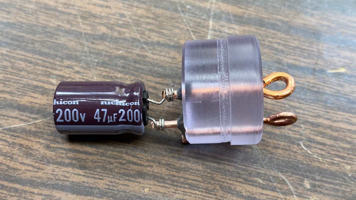
The new Nichicon is now attached to the wire terminals.
I twisted the leads of the new capacitor around the appropriate wires, as shown above, and then soldered the leads in place.
I did not have any fish paper, so I used a piece of heat shrink tubing to insulate the wires and prevent either of the wires from making contact with the aluminum can.
The plastic cap, with terminals and new electrolytic, is ready to attach to the metal top.
Once the heat shrink tubing was put into place, the top and cap were ready to be pushed together.
The finished product.
The picture above shows how the first capacitor turned out.
With one can complete, I turned my attention to the other can and cap.
This can was going to house two electrolytic capacitors – a 33 uF Panasonic capacitor and a 22 uF, 25 volt Xicon cap. I had had the Xicons on hand for a number of years, and I use these primarily for cathode bypass capacitors for audio output tubes in AC-DC radios.
The other capacitor is assembled in a similar manner.
I cut the wires protruding from the top of the plastic cap just enough to accommodate the two electrolytics, and then attached and soldered these to the wires in a similar manner to the first cap can.
Once this had been done, I used heat shrink tubing again for insulation. Finally, the plastic cap was pushed into the end of the aluminum can.
I really need to get some fish paper.
The replacement capacitors (center) with the original electrolytics (left and right).
At this point, the cans were ready for installation into the radio chassis. I pushed the original old fiber insulators over the ends of the new cans, as at the time
I thought I would be using these to give the new cans more of an original appearance.
However, I would soon run into a problem.
Whoever had worked on this radio in the past had removed the rivets which originally held an important clamp to the chassis. This clamp holds the electrolytics in place on the chassis. I do not have access to any type of riveting equipment other than pop rivets – and pop rivets would not work in this instance.
I used 6-32 screws and nuts to hold the clamp in place, as you can see in the photo below. Unfortunately, this prevented the cans from fitting into the clamps with the fiber insulators in place.
So, I removed the insulators and installed the cans into the clamp “as is”. I had constructed these cans so that the negative terminals made no connection to the cans. I even checked this with my DMM to be certain there was no contact between the negative terminals of either can and the can bodies themselves. All was well.
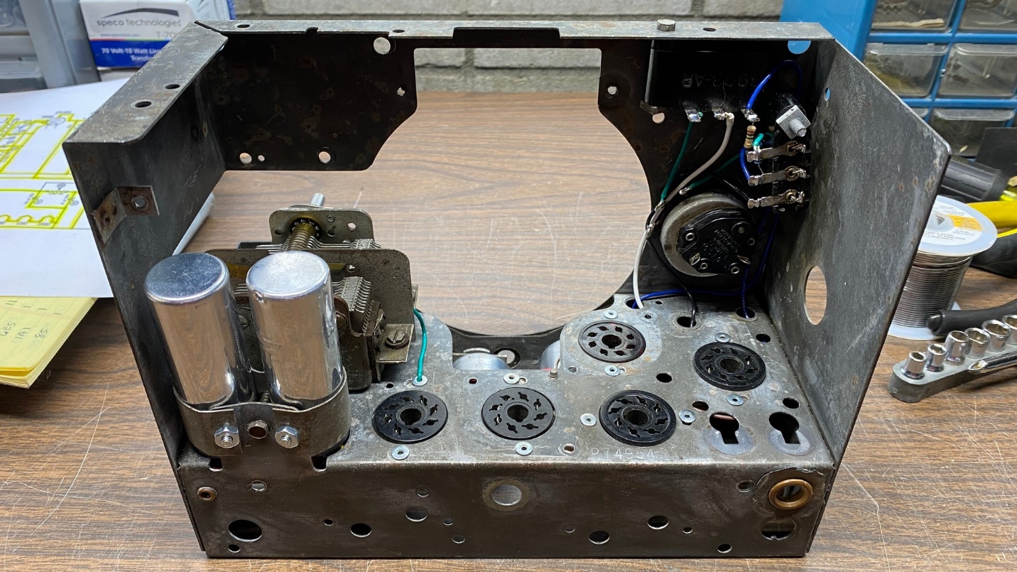
The new electrolytic cans have been installed in the radio chassis.
I also wired the new cans under the chassis. I knew that I would not be able to do this once the antenna coil and band switch were back in place, so now was the time to do this.
I had intended to use a 1.2K, 1 watt resistor in the power supply circuit between the 47 uF and 33 uF electrolytics. I looked in my stock of resistors, and found that I had no such resistor. However, I did have a 1.1K, 2 watt resistor. I felt that would be close enough, and it went into the chassis.
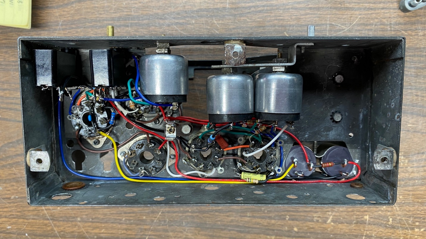
The new parts have also been connected under the chassis.
With these major parts in place, I spent the next few days continuing to reinstall various small parts and wires.
After many more hours of work, the radio is almost complete.
I had decided to hold off on installing the speaker until the very end, as I did not want the speaker to become damaged in any way. As it turned out, I ended up installing the speaker and hooking up its wires before I hooked up the IF trimmer assemblies, simply because I needed the room under the chassis to solder the speaker wires in place.
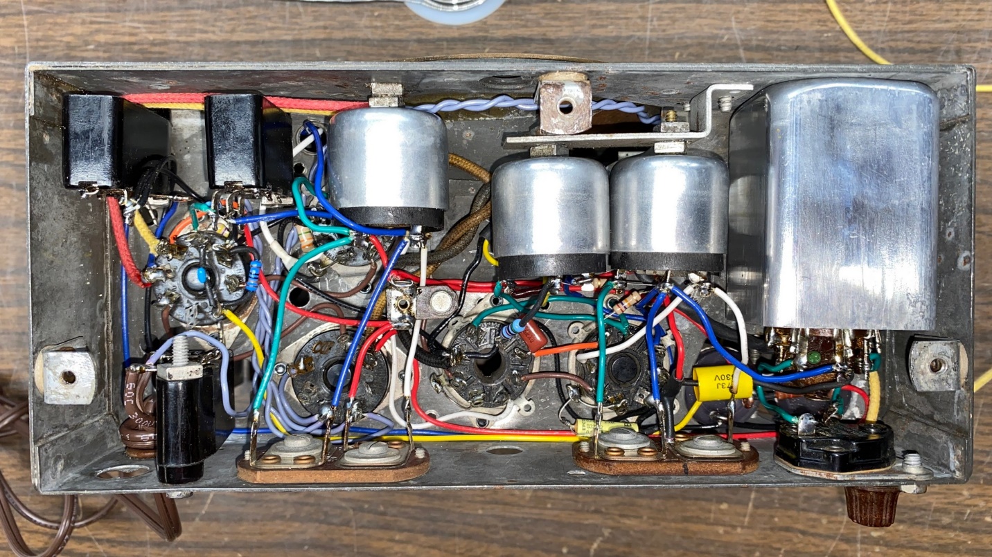
Things are still pretty tight under the chassis.
I reached a point that I thought I had completed work on the chassis, and then I happened to glance down at my workbench and noticed the low frequency padder, lying there on the bench. This part was also installed and wired into place.
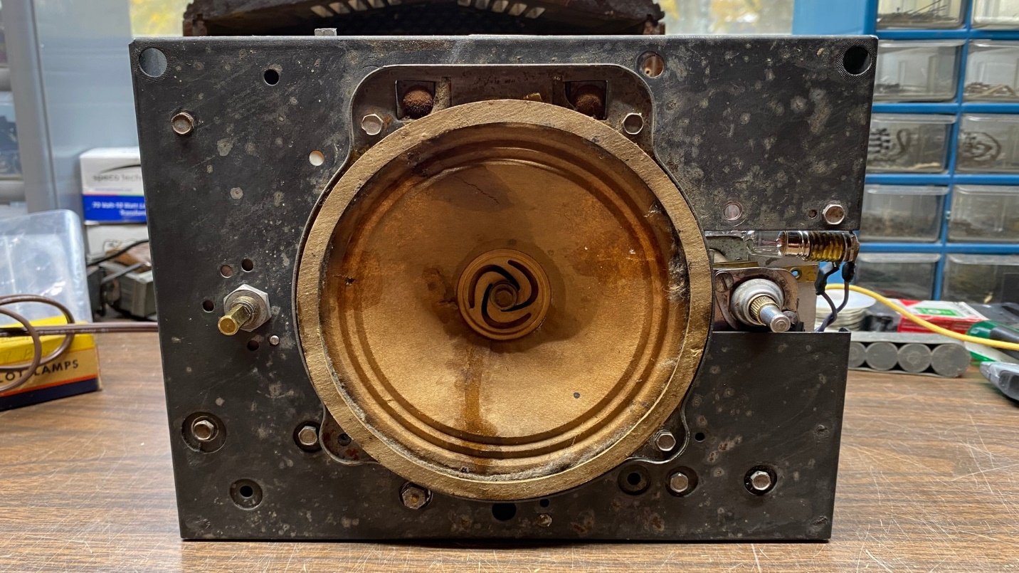
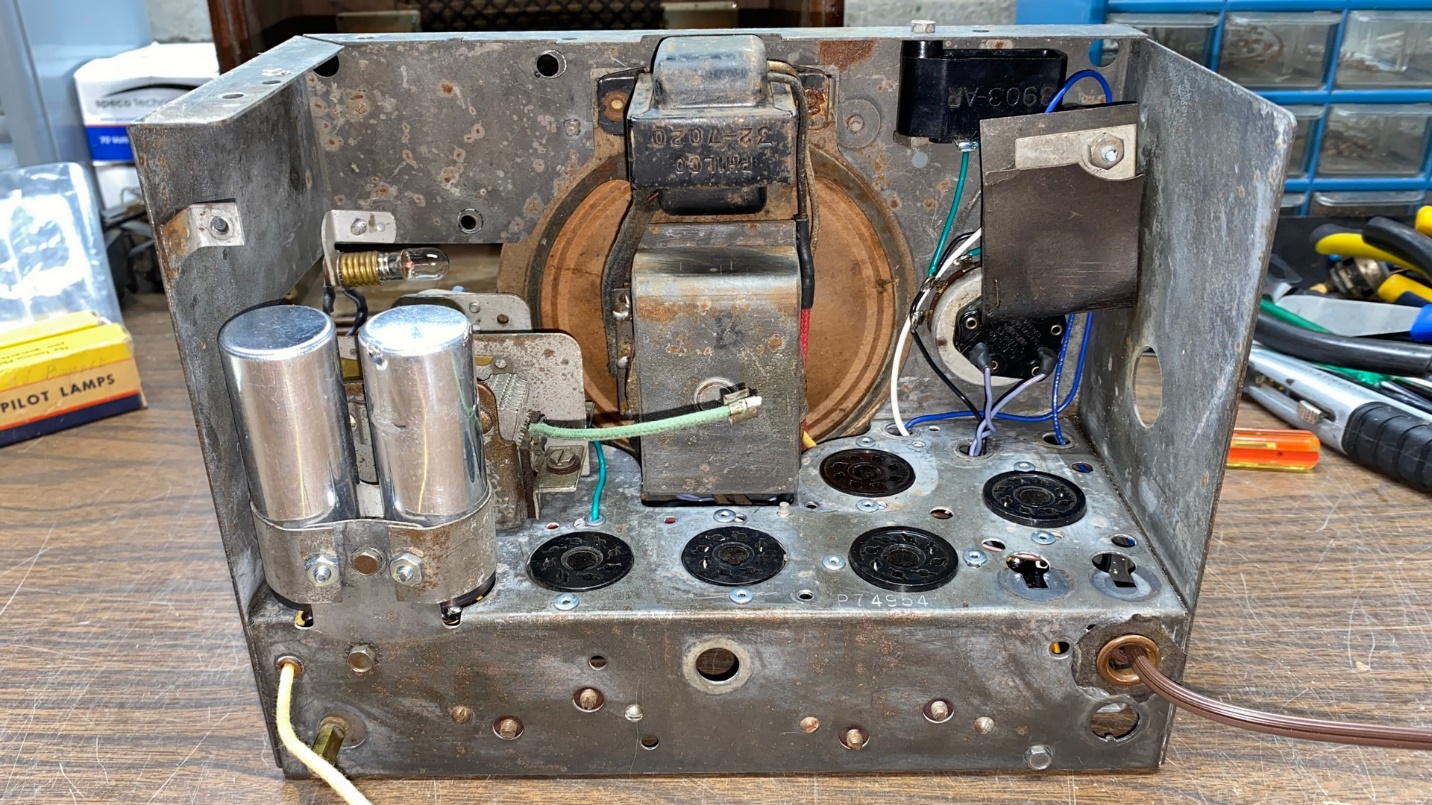
Front view of the rebuilt chassis.
At long last, the radio rebuild was complete!
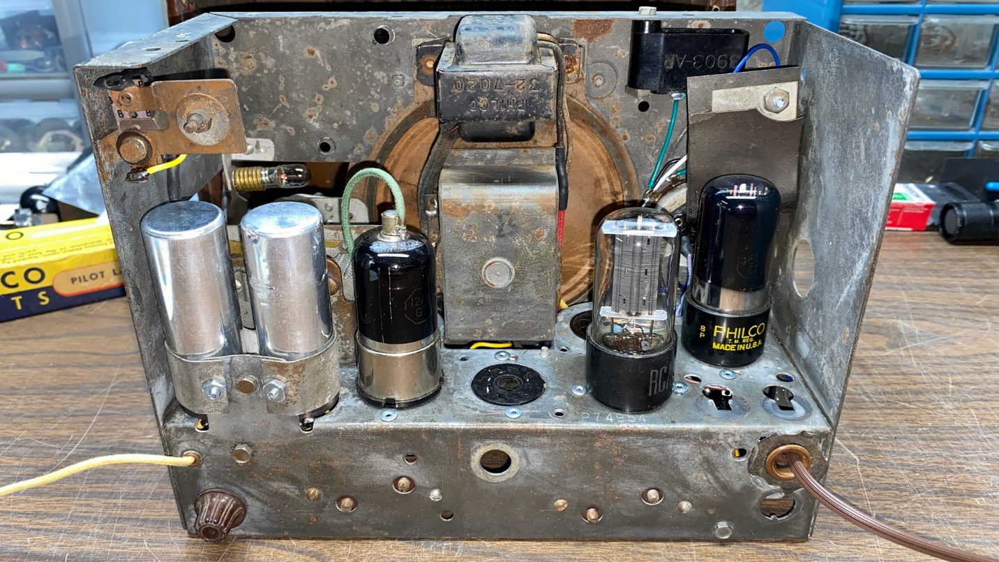
Almost ready for its first trial run – waiting for two tubes.
As you probably noticed in the two photos above, the underside of the chassis is still tightly packed. However, the top of the chassis is obviously less cluttered since it no longer has the filter choke or the multi-section rectangular can capacitor.
I had three of the five tubes I needed on hand already, but I did not have the needed 12SK7 and 12SQ7 tubes. So, this chassis will be set aside until those tubes arrive.
Next time, I will install those tubes and try this set out. Until then, stay tuned!