I do not remember how long I have owned this particular Philco model 90 chassis, nor where it came from. For the past several years it has resided inside a reproduction cabinet made by Steve Davis. (You can get your own by going to this page.)
Recently, I decided that it was about time for me to either do something with this Philco 90, or get rid of it. As the 90 is one of the iconic receivers in the radio collecting hobby, I chose the former.
This chassis came with its own set of minor challenges – it had no speaker, its large tube shield is the wrong one (the chassis is the “mid” version with a single 47 output tube, the most common of all 90 sets, while the shield is from an “early” chassis which used two 45 output tubes), and the chassis itself was filthy.
The cabinet currently has no escutcheon, but I have one on hand. It also has no grille cloth; I have that on hand as well. Finally, it has no knobs. I have a set I can use, however.
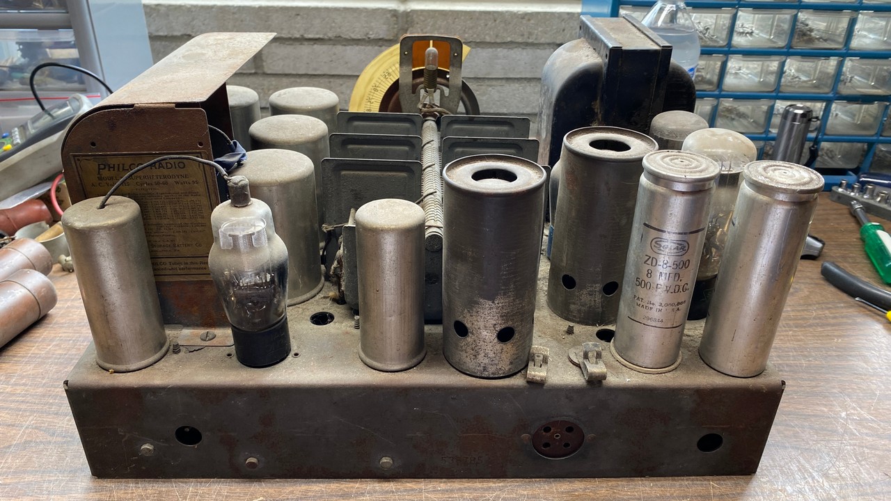
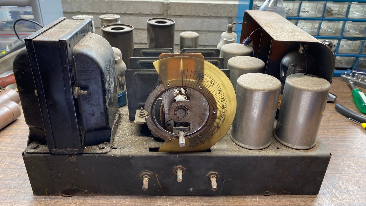
Back view of the Philco model 90 chassis.
Looking at the back of the chassis (see photo above), you can see right away that the two large electrolytic capacitors are replacements with shells made of aluminum. Originally, Philco used mostly copper-shelled electrolytic capacitors manufactured by the Mershon Condenser Company. It should be noted that occasionally, 1931 model Philco sets such as models 50, 51, 70, 90, and the late versions of model 112 have been found with Sprague electrolytic capacitors, which use nickel-plated copper containers. The Spragues appear to be factory originals also. It is possible that Philco may have used Spragues when they ran out of Mershons. This, however, is not a known fact but merely conjecture.
In any event, I will replace those aluminum Solar electrolytics with copper Mershons. You may see these just below.
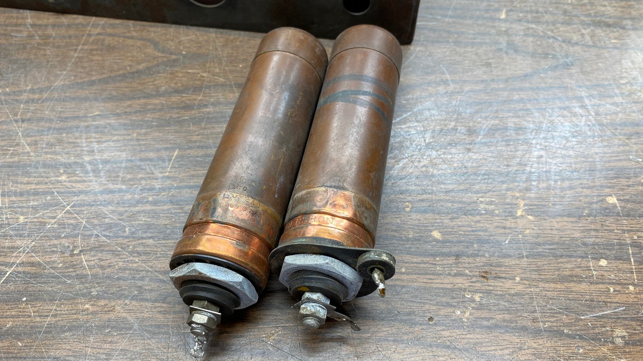
The 8 uF Mershon electrolytics I plan to use in this Philco 90.
It should be noted that these two Mershons are 8 uF instead of the original 6 uF units used in model 90. As a consequence, they are about an inch taller than the originals. However, this should not be an issue as they otherwise look much like the originals, and few people would know the difference.
Philco used these 8 uF Mershons in some model 16 and 17 console and chairside models. These must have been salvaged from either model 16 or 17 chassis.
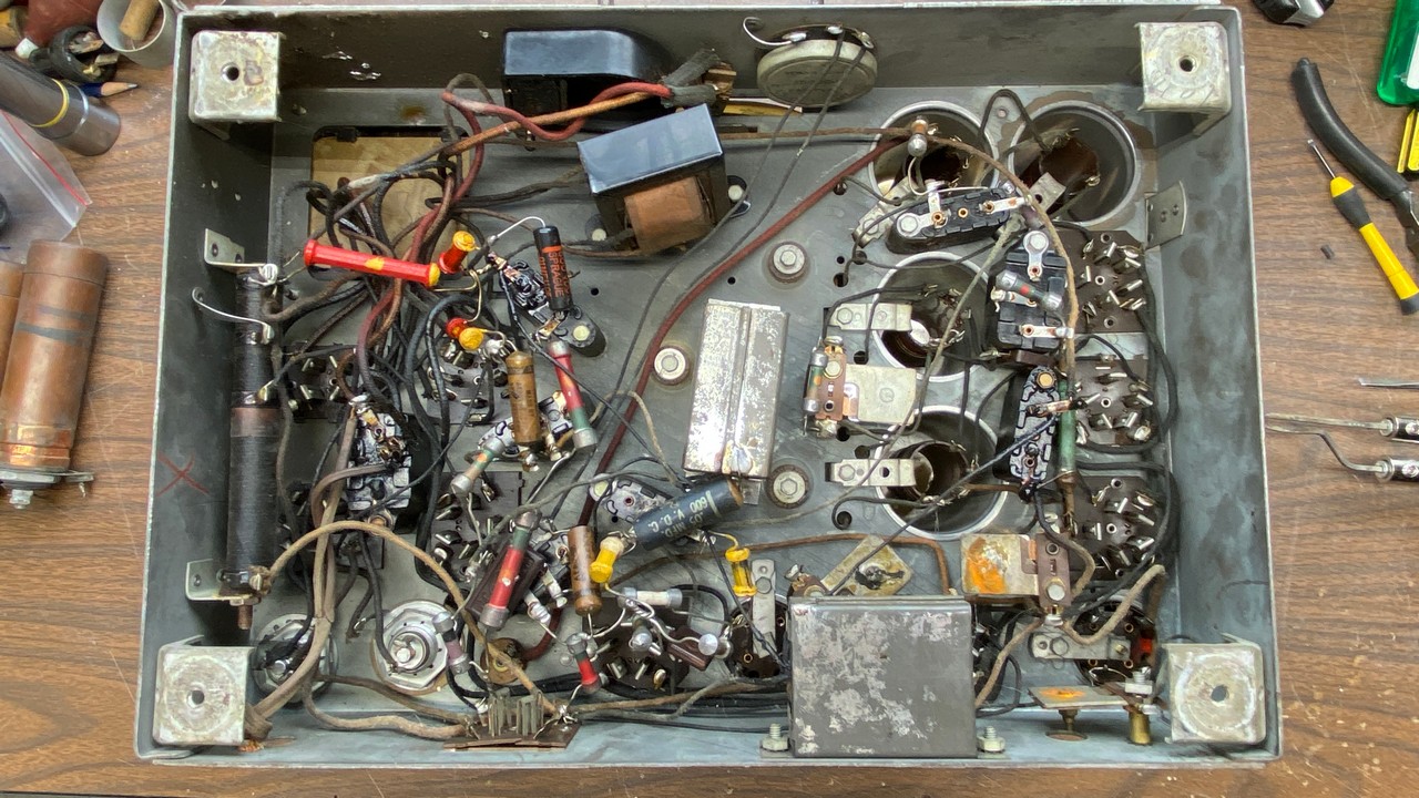
Under-chassis view of the Philco 90.
Looking under the chassis, I could tell that it had only been serviced slightly during its time as a working radio. Two of the bakelite block capacitors had been bypassed with tubular capacitors, a common practice by various radio repairmen. Other than these and the Solar electrolytics, this chassis appeared to be as original.
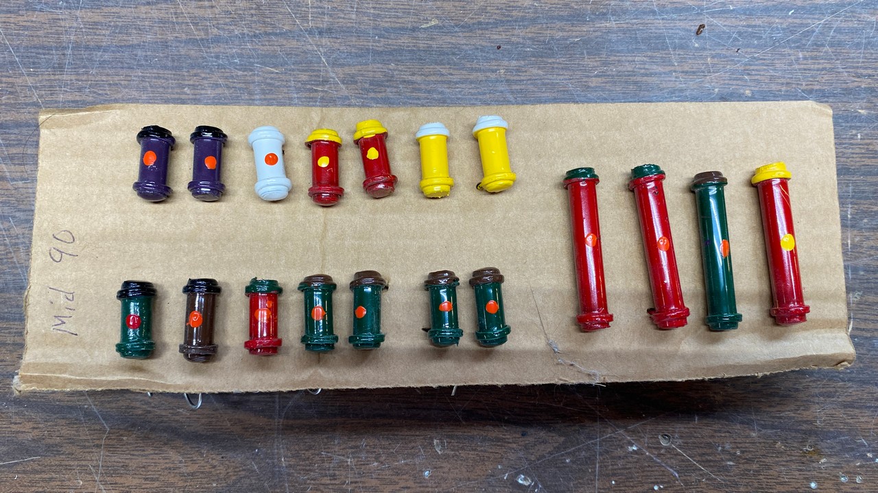
Reproduction dogbone resistors for a truly authentic appearance.
For several years now, for almost as long as I have owned this chassis, I have had a set of reproduction Philco dogbone resistors which were made specifically for this version of the Philco 90. These were furnished to me by Steve Davis. I greatly appreciate having these parts, and I plan to finally put them to good use. With the use of these resistors, the under-chassis appearance of this 90 will be very authentic – more so than my typical restorations which contain new resistors. I think it is great that some folks go to the extra trouble to make these dogbone resistors. I never have, however, as it just seems like too much work for me.
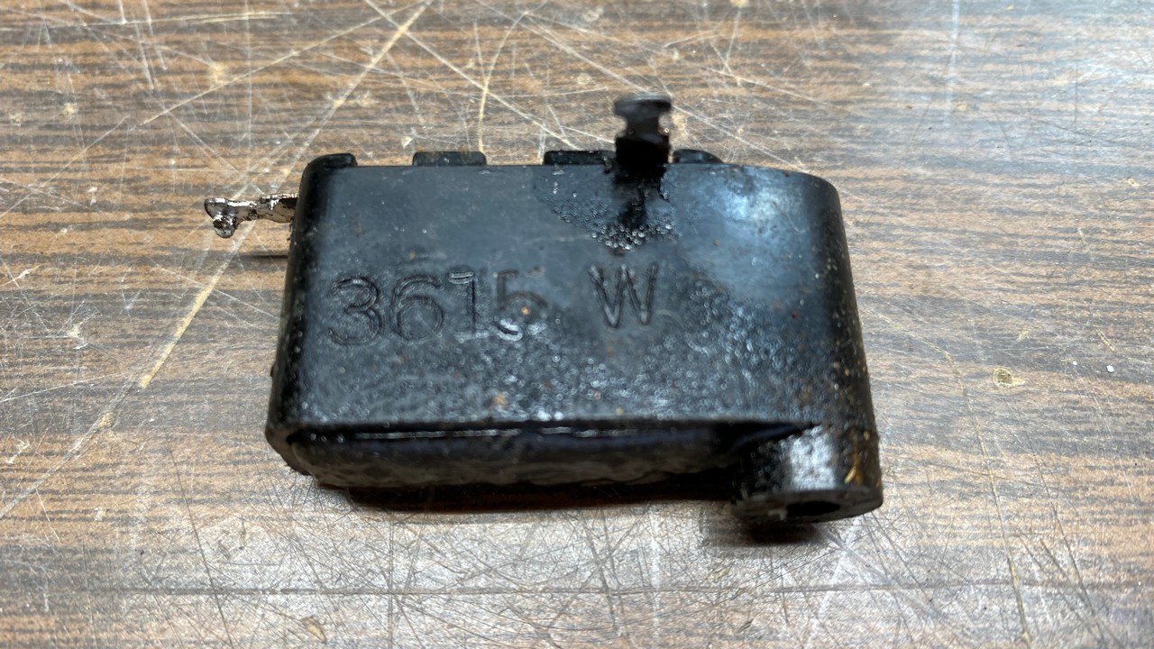
A Philco bakelite block capacitor.
I decided to begin the work by rebuilding the bakelite block capacitor located next to the set’s antenna coil. This block contained a .05 uF capacitor encased in a waxy substance.
As I had mentioned in my recent account of restoring a Philco 59C, my procedure for rebuilding these blocks is to remove one from the radio, heat it up with a heat gun, then use one of Steve Davis’ handy tools for pushing the waxy plug and old capacitor out from one of the little holes in the top of the block.
Some folks prefer to perform this job with the block still connected to the wiring inside the radio, only removing the mounting screw, heating the block, and pushing the insides out. Then they flip the block over, remove the insides from the block, install a new capacitor or capacitors, then flip it upright again and reinstall the mounting bolt.
I do these one at a time by removing each one from the radio as I prefer not to risk the possibility of damaging a wire. In addition, removing the block allows me to clean it up a bit before I install the new component(s) and put the block back into the radio.
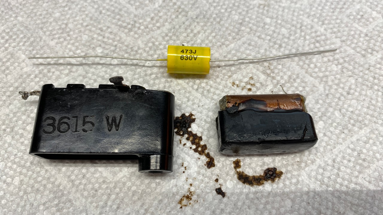
A Philco bakelite block with its insides removed. A new capacitor is ready to install inside the block.
Before long, the block was restuffed with a new .047 uF, 630 volt yellow film capacitor, and reinstalled in the radio chassis.
One block down, seven to go…
I managed to restuff one more bakelite block before I ran out of desoldering wick and had to quit. Yes, I know, I probably should have had a desoldering station the past several years, but it’s a little too late for that now, I think. I do have more desoldering wick on the way. It was supposed to have been delivered on the same day I started working on this radio. However, as many of you know, the shipping companies often do not deliver on the days they say they are supposed to.
We’re running out of space for now, so I will likewise stop writing while I wait for that desoldering wick. Next time, I will continue restuffing bakelite block capacitors and installing some of those good looking dogbone resistors as I go along. Please join me then.