
Call me crazy. I had put a lot of work into a 1929 Philco model 87 only to find that its power transformer was bad. So, what do I select for my next project? Another 1929 Philco, of course – this time a model 65 table model radio.
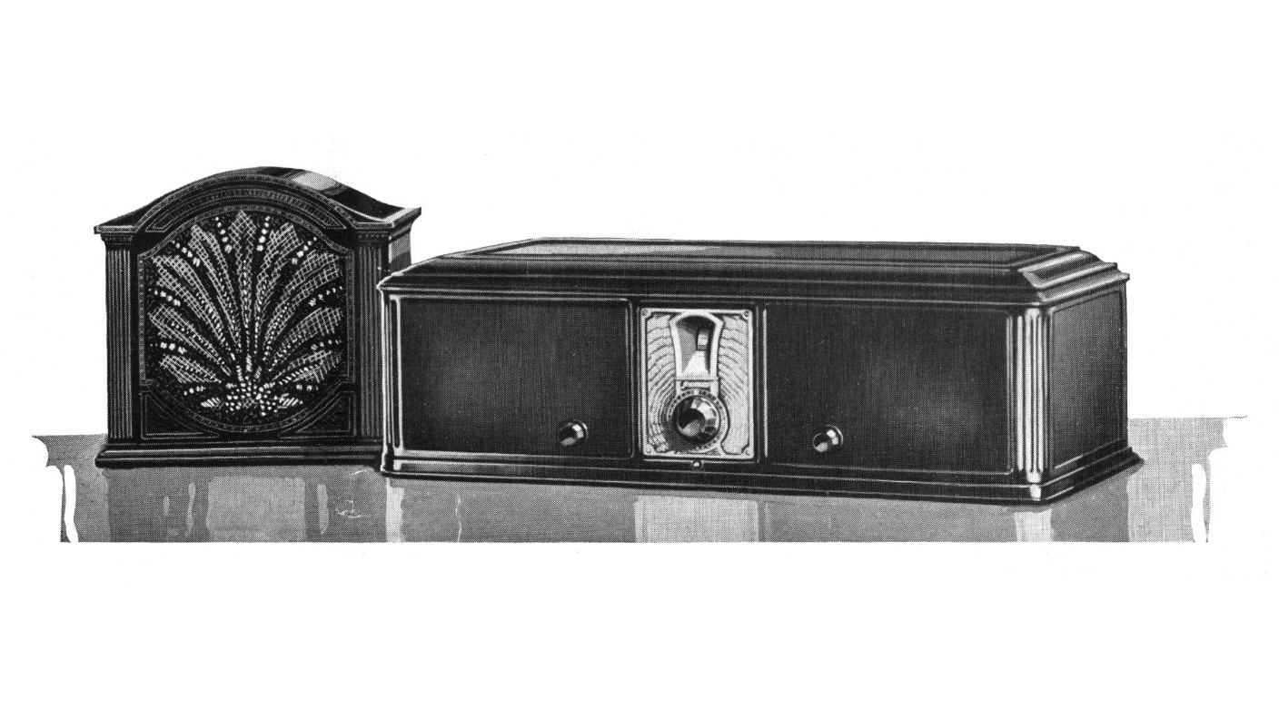
1929 Philco model 65 with matching F-10 speaker. Illustration from Philco sales material.
Like the model 87, model 65 was introduced in June 1929 and was available in lowboy, highboy, highboy de luxe and metal table model cabinets. Unlike the 511 series of 1928, however, the 65 table model only came with Spanish Brown paint from the factory.
Debbie had bought and given this model 65 to me, complete with matching F-10 speaker, close to a decade ago. It had been sitting around ever since. I decided now was the time to finally get around to doing something with it.
I forgot to take a “before” picture of the radio with its speaker, so I have posted a factory illustration above instead to give you an idea of what this radio looks like.
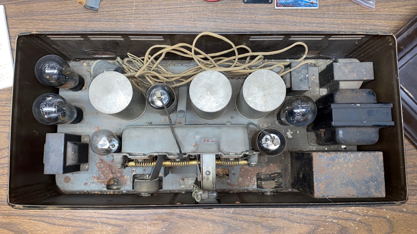
Model 65 with a complete set of Cunningham globe shaped tubes. I hope they are all good.
Determined not to repeat the mistakes I had made with the 87, the first thing I did was to place the radio on my workbench, remove the top, flip it over, and remove the bottom cover.
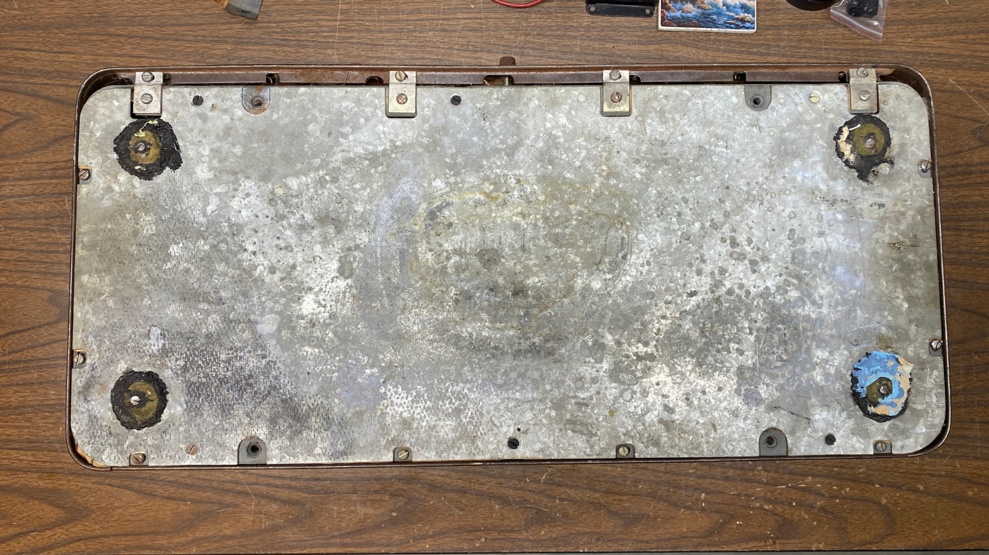
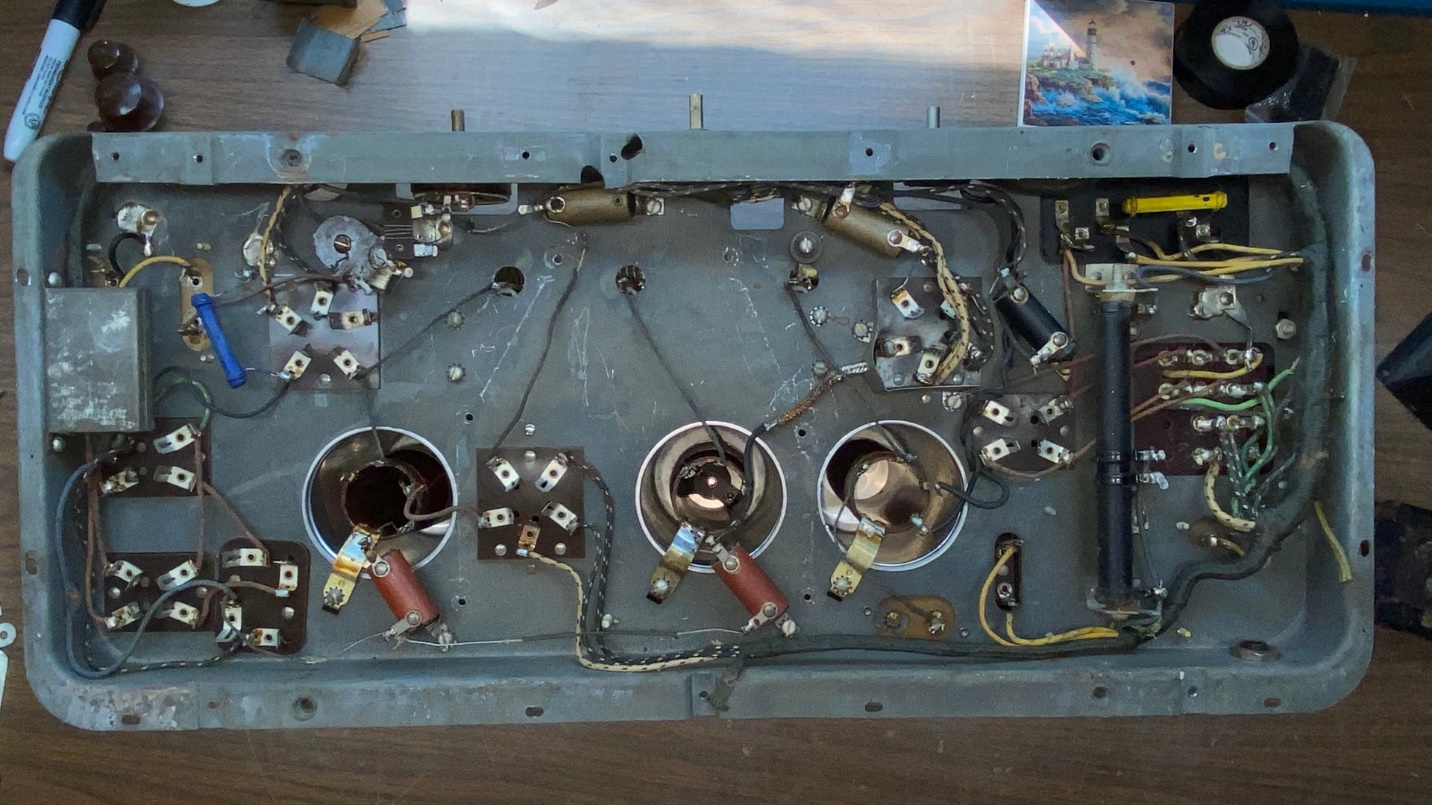
Bottom view of model 65. The original rubber feet had long since melted/crumbled away, and will need to be replaced.
I sort of suspected what I was going to find, but things were even worse than I thought they would be underneath the chassis.
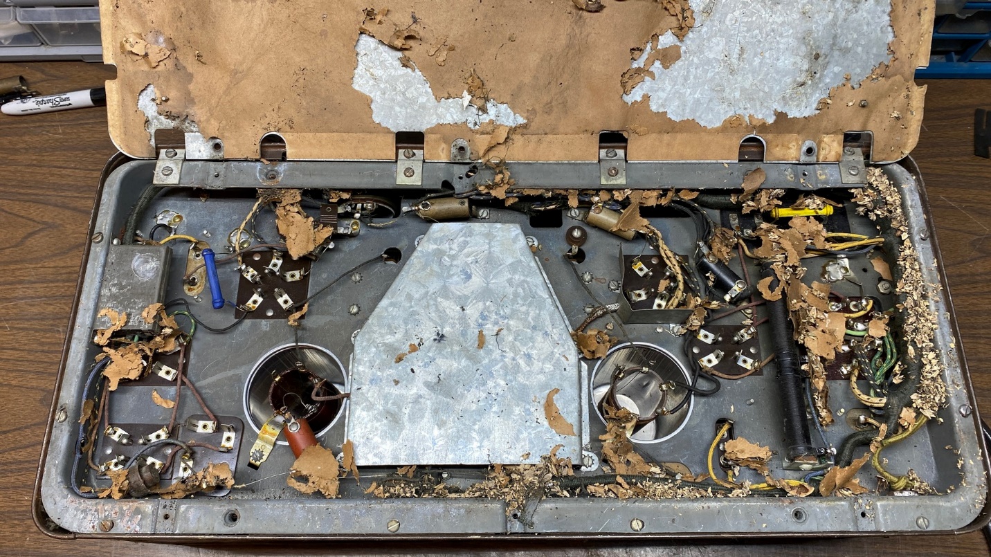
Surprise! Mice had obviously been inside this chassis.
Ah, Mickey and Minnie had set up housekeeping inside this model 65 chassis at some time in the past. They chewed up much of the paper insulator under the bottom cover, and that paper will have to be replaced. The remnant of the original paper was promptly disposed of.
Using my vacuum cleaner, I soon had all the old mice chewings and deposits taken care of. You can see the results below.
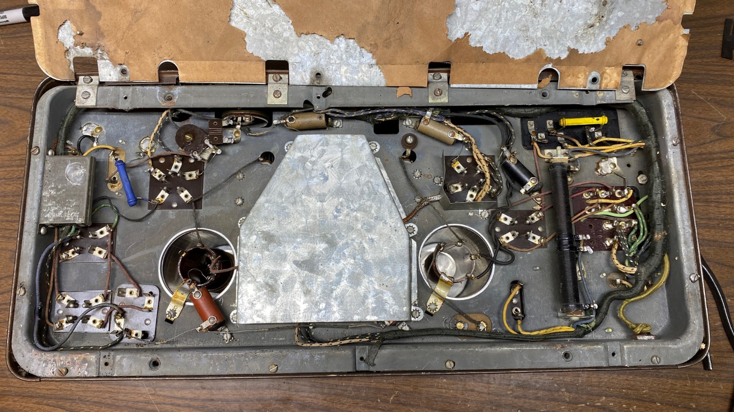
After thoroughly vacuuming under the chassis, it now looks like this. The large piece of paper which goes under the bottom cover will have to be replaced.
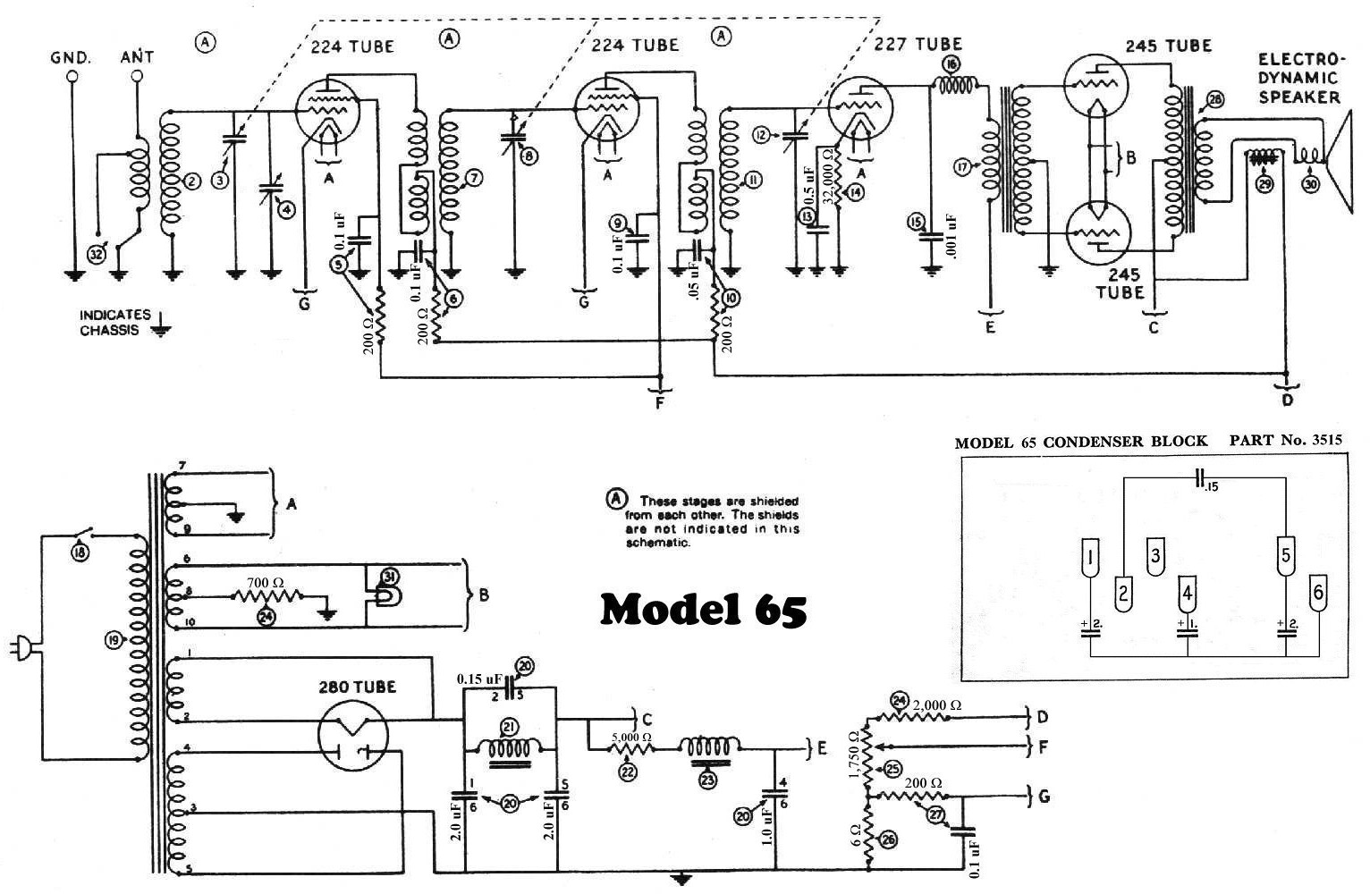
I set the bottom cover aside and then, using my digital multimeter, began checking the power transformer terminals against the schematic and under-chassis illustration. (You can find the service information for model 65 HERE and HERE.) Lo and behold, this power transformer checked out good! All windings had good continuity.
And the main winding I was concerned about – the high voltage winding – showed a total of 345 ohms across the entire winding. One half of the winding, from 80 plate to ground, read 168 ohms; the other half, from the other 80 plate to ground, read 177 ohms. It is normal to have a small discrepancy in the resistance reading due to the way these transformers are wound. However, a large discrepancy always indicates a partial short in one of the windings.
I checked the large two-section resistor, part (24). Both sections were good!
I then moved to the only other part in the radio which might be difficult to replace, that being the volume control. In this radio, the volume control is wirewound, having a resistance of 1750 ohms, and controls the screen grid voltage of the two RF amplifier tubes (224). Unfortunately, this control is open. I sort of expected that, but I was of course hoping I would be wrong, and that it would be good. Experience with early Philcos has taught me that this type of volume control is usually bad in these sets.
I have not yet checked the coils, but I am confident that I can repair those if any happen to have open windings.
Since the power transformer seemed to be ok, I made the decision to proceed with the restoration. The next step was to remove the bare chassis from the metal cabinet. This was not too difficult. It involved removing several screws and four brackets under the chassis, carefully flipping the entire thing right side up, and then carefully working the cabinet up and away from the chassis.
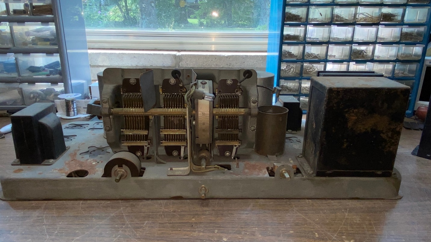
After removing the chassis from its metal cabinet.
Once the chassis was free from the cabinet, I continued vacuuming up dust and debris, with the assistance of an old paint brush.
Considering mice had been in this chassis, it actually is in pretty good shape with only a couple obvious rust spots. The paper insulator under the bottom cover of the chassis must have mostly satisfied the appetites of the mice, since only a few wires underneath have chewed or missing insulation.
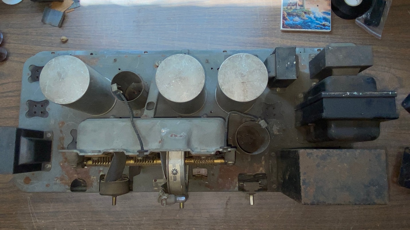
Top view of the bare 65 chassis.
This should be an interesting restoration. Model 65 was only on the market for a few months before being discontinued in Fall 1929 in favor of a new model, the 7-tube model 76.
How the chassis looks underneath after the center shield had been removed.
Next time, we will get started in earnest by rebuilding the large filter condenser can. Stay tuned.