It was time. I had been putting this off for two months (notice my last post on this subject was on April 12). Part of the reason for the delay in trying out the 38-690 was due to the chemotherapy I was going through and how it was making me feel progressively worse. And, I will admit, the other part was because I frankly dreaded it. The repair of this radio has been one major issue after another.
Yesterday afternoon I was feeling better than I had in some time. So I knew this was the time to finally assemble the 38-690 on the workbench and try it out.
I began by pulling out the amplifier/power supply chassis, also known as the “lower” chassis. I found the box of tubes and began to install them. My cat, Viktor, seemed to approve as you can see below.
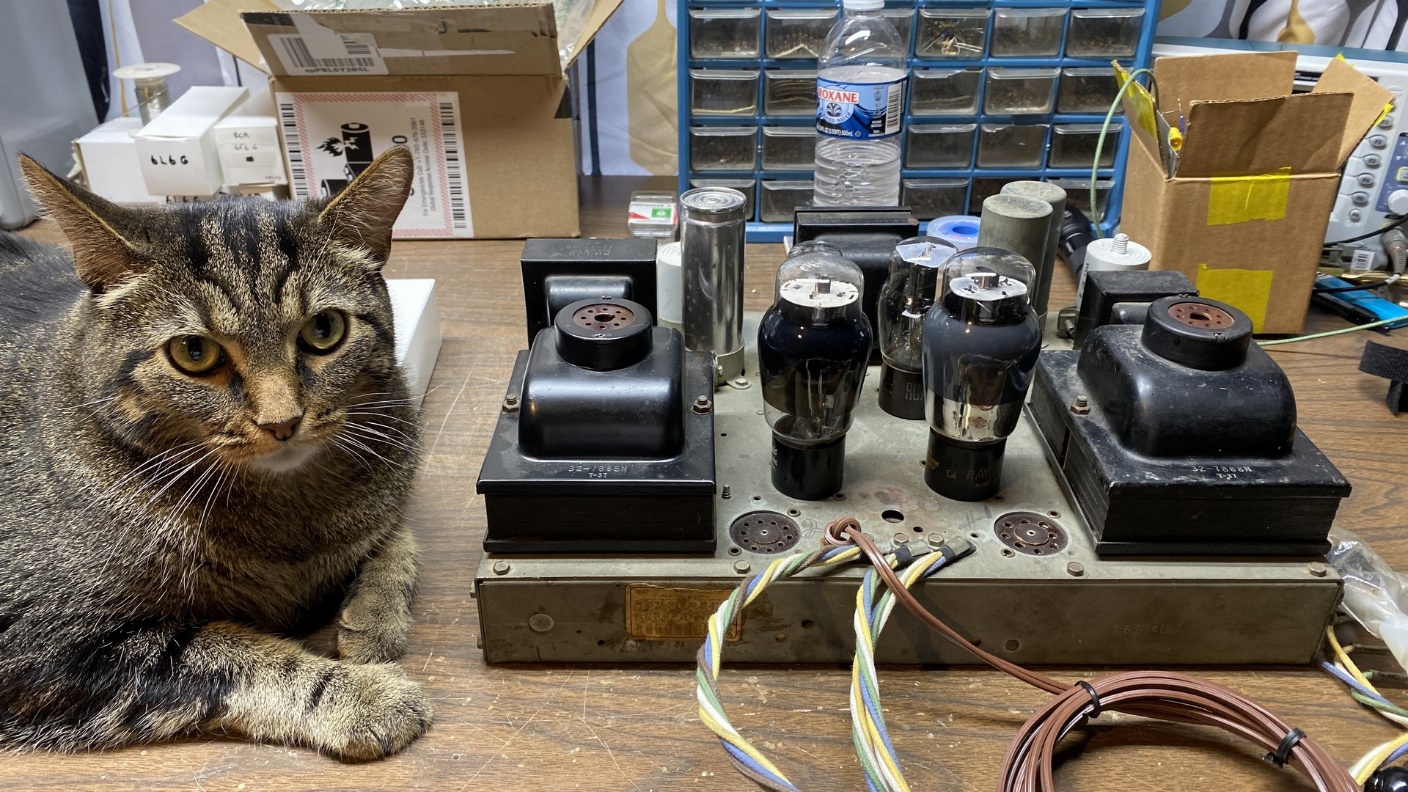
Viktor standing by as I begin to assemble the 38-690 on the workbench.
When I got to the two 5X4G rectifiers, I found that there was one 5X4G in one box. The other box, labeled “5X4G” contained a 5Y4G.
Oops.
I checked my tube inventory and found that I had no spare 5X4G tubes. I also do not own any radios which use the 5X4G tube. And then I noticed on my tube inventory spreadsheet I had a 5U4GB listed with a 5X4G adapter!
Yes, back when I owned a 37-670B, I had constructed this adapter to test the 37-670B chassis after repairs had been done to it. So, this would serve the purpose of a 5X4G, and it was promptly installed on top of one of the dual power transformers.
Next, I had to remove Viktor from the workbench so I could put the RF-IF chassis, also known as the “upper” chassis, on the bench. Viktor was temporarily moved into another room while I connected the two umbilical cords from the upper chassis into the lower chassis. Finally, the woofer and two tweeters were pulled out and connected, followed by my longwire antenna.
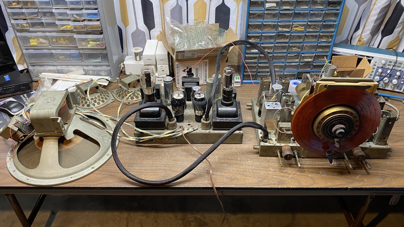
38-690 upper and lower chassis and all speakers, hooked up on my workbench.
I plugged the 38-690 into my Variac. Turning on both radio and Variac, I slowly brought it up to 110 volts AC.
No weird issues were noted. No popping or sizzling. That was a huge relief!
The radio finished warming up and I began to hear typical AM noises. I tuned around the AM band but could not pick up much. Placing my finger on top of the 6U7G RF tube, AM sounded stronger. I immediately thought, Oh boy, just what I need – to have to pull the @#$%&^!!!! RF unit out again!
I checked the four SW bands and I could pick up typical AM noise as well as a few stations.
Issues:
- As noted above, the AM RF coil may have a problem or even be open. But then again, it may not – I noticed after I finished my test and was unhooking everything, that I had my longwire turned off – the switch was in the “grounded” position. DUH! So the AM RF coil may be OK after all. I can check it with my multimeter without removing the RF unit.
- The tuning mechanism is very stiff and tight – so much so, that when tuning up the band, the bandswitch wants to switch to higher bands on its own. This will have to be dealt with.
Otherwise, everything seems to be OK. The modification to remove the grounded connections from switch wafer C seems to have been a success.
So, this radio may be getting close to being ready to go back home. I hope so, anyway. The next thing to do is to check the AM RF coil. Then, find out why the tuning is so stiff, to the point that is causing some binding with the bandswitch assembly, and fix these issues.