Replacing Wires on IF Transformers, and reinstalling the tuning condenser.
With the 6A7 socket successfully replaced, I turned my attention to the three IF transformers. You may recall that I had mentioned previously that I felt the wiring of these warranted replacement.
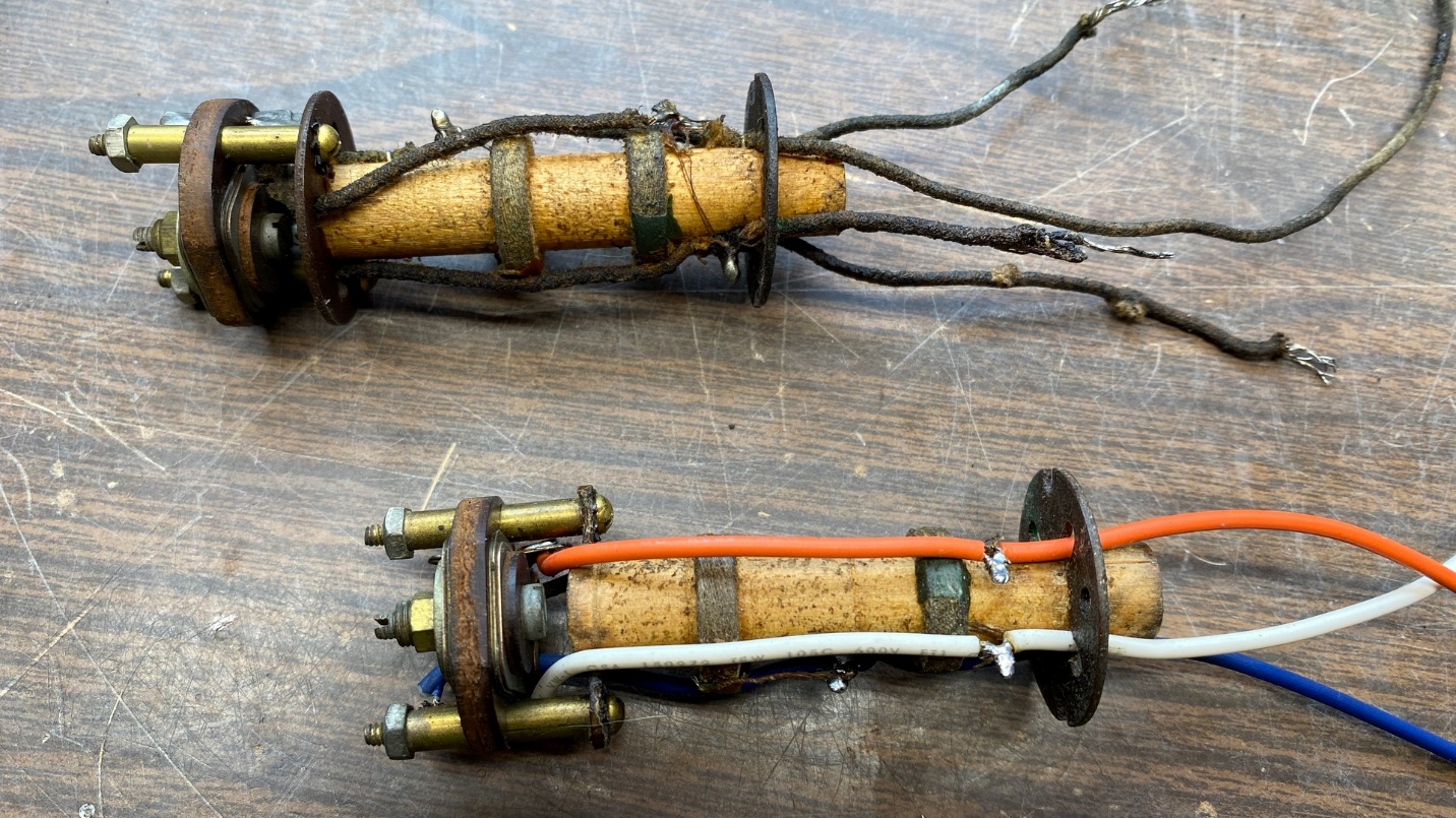
The 3rd IF transformer(top) and 2nd IF transformer (bottom) of the Philco 29. Notice that the wires have been replaced on the 2nd IF transformer.
To make the IF transformers easier to install and to service later on if the need ever arose, I decided to observe the more conventional color coding for the wires. Only I had no stranded red wire, so I used orange instead.
The IF transformers turned out to be easier to rewire than I thought they might. Soon, I had all three rewired and reinstalled in the radio.
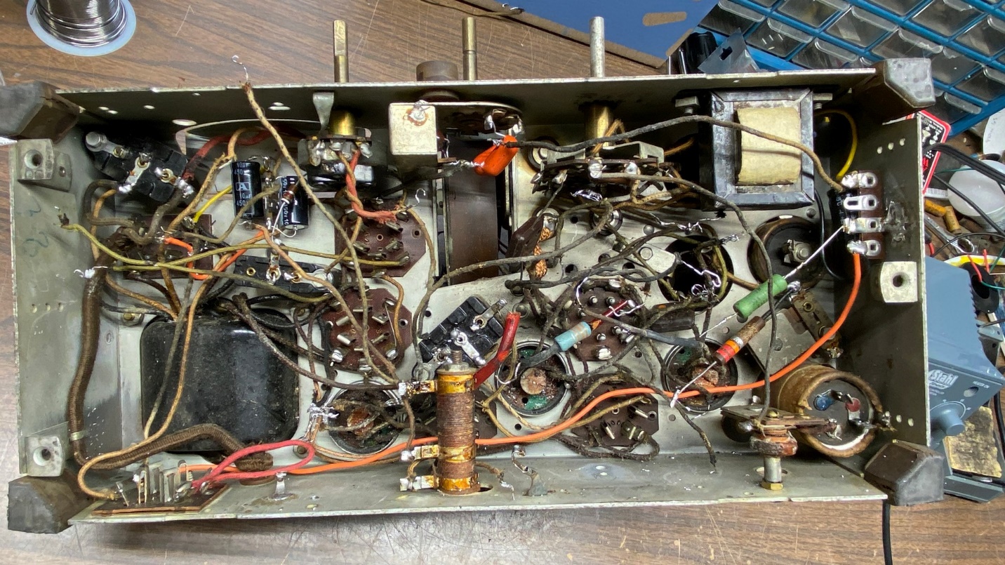
Top view of the 29 chassis showing the 1st and 2nd IF transformers back in place.
In attempting to measure the length of wire needed for the grid wire coming out of the 2nd IF can, I mistakenly cut it off too short. I considered removing the transformer from the can and redoing it, but I ended up taking the easy way out and simply lengthened the wire instead by soldering a short piece of wire to the end. I used heat shrink tubing to cover the solder joint.
I noticed that I needed to reinstall the tuning condenser before I could reinstall the terminal board which contains capacitors and resistors, and which mounts under the 6A7 tube. In order to do that, I needed some new rubber grommets for the tuning condenser. Renovated Radios in Michigan is normally the go-to source of gum rubber grommets for various radio applications, including tuning condensers. The company was recently sold to a new owner. At the time (mid-March), they were not taking orders while they were getting things situated. They have since reopened and are taking orders for parts once again.
So, with Renovated Radios temporarily out of the picture, I needed another source for rubber grommets.
McMaster-Carr to the rescue!
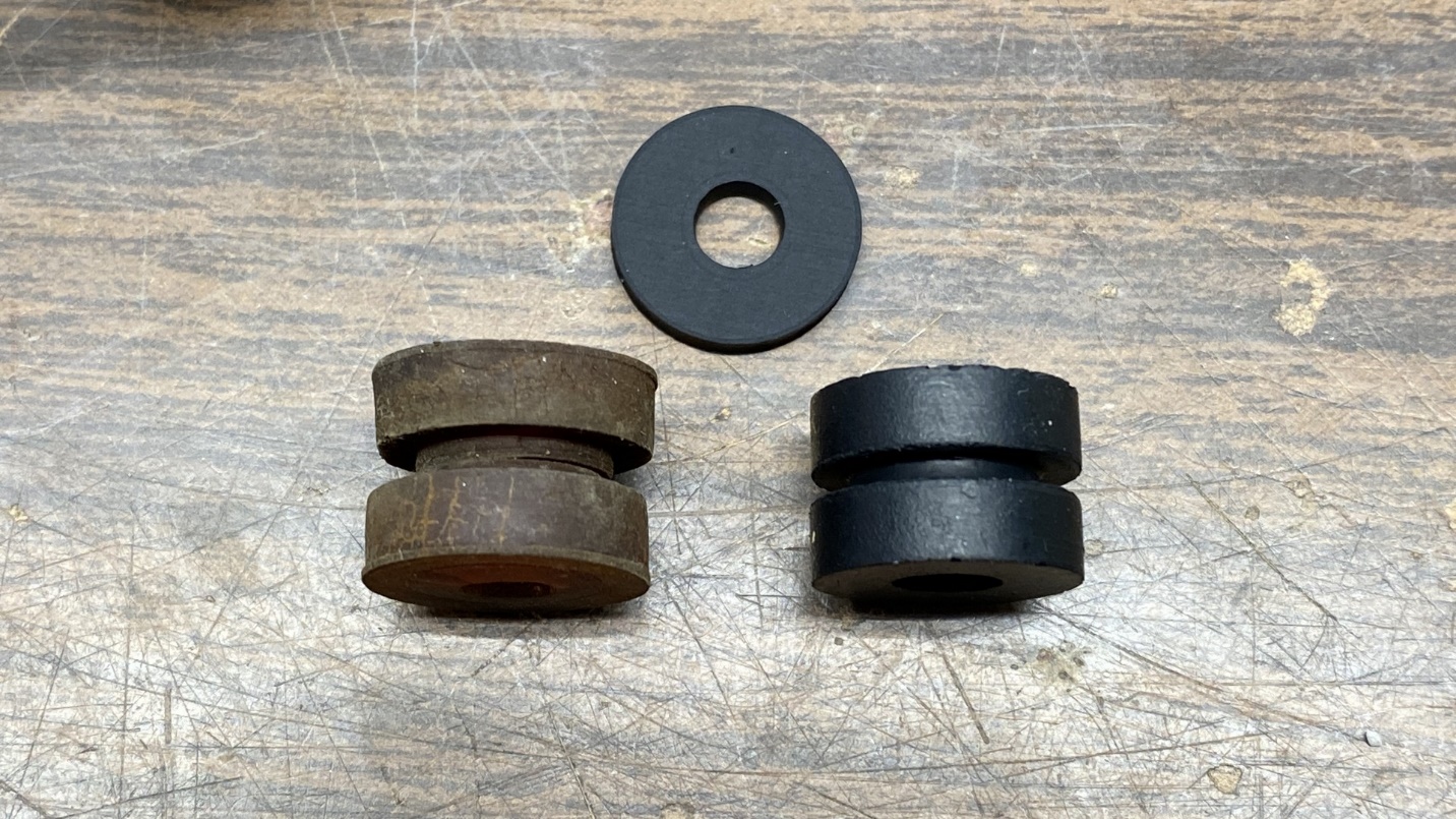
Original two-piece tuning condenser grommet (left) and a new McMaster-Carr one-piece grommet (right). The flat rubber washer will make the new grommet tall enough for the purpose.
McMaster-Carr carries a wide variety of hardware, including several types and sizes of rubber grommets. After a bit of research on their website, I found some one-piece grommets which I felt would be a good replacement for the original two-piece Philco tuning condenser grommets.
The tallest grommets McMaster-Carr carries of this type were not quite tall enough for the purpose, so I also found some flat rubber washers which, when glued to the top of the new grommets, would make the new grommets the proper height for the tuning condenser.
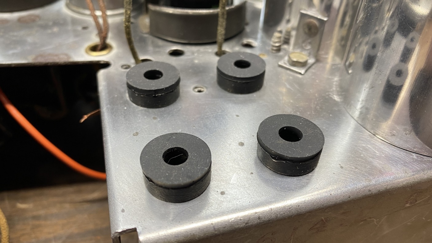
New tuning condenser grommets in place on the chassis, with new flat washers glued on top of each one.
You have to buy grommets from McMaster-Carr in bulk (bags of 50 in this case).
I placed the order, which included the replacement tuning condenser grommets, flat washers, and some conventional rubber grommets for other purposes. The order was delivered the next day. That’s great service!
It was difficult to install those grommets into the chassis due to their thickness, but I persevered, and prevailed. Once all four were in place, I carefully glued a flat rubber washer on the top of each grommet with super glue. The end result can be seen in the photo above.
Now the real fun began – reattaching the tuning condenser to the chassis.
Setting the chassis vertically on one end, I began the process of lining up the holes for the mounting bolts and then installing each bolt, one at a time. Since I was now using single-piece grommets instead of two-piece grommets, I did not have to worry about grommets falling out or otherwise coming out of place.
Soon, the tuning condenser was back on the chassis.
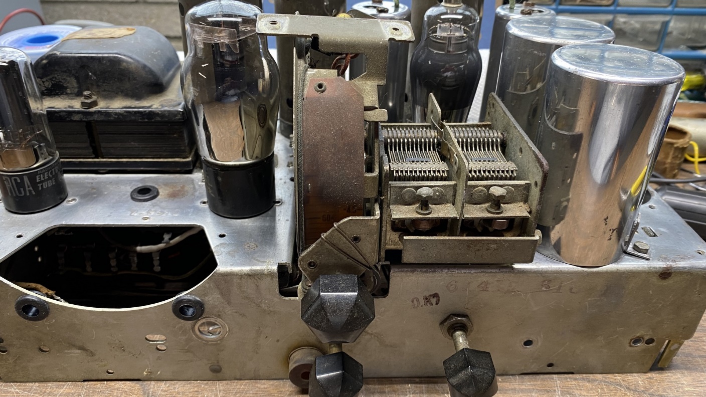
The tuning condenser is now securely mounted on the chassis again.
I then proceeded to connect the wires to the tuning condenser, after which I finished connecting wires and components to the 6A7 tube socket. Next, I reinstalled the two terminal boards which hold various capacitors and resistors and connected most of the necessary wires to their terminals.
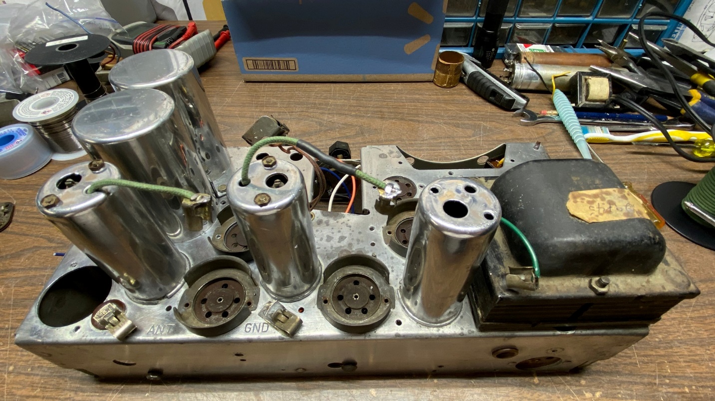
I could see that I was going to have to attach the speaker before I could go much further in reconnecting things under the chassis. As you can see in the photo above, I had previously removed the metal plate which covered the area where the 5 inch speaker would be attached on a 45C chassis.
I had acquired a speaker from a Philco 610B some time ago, which is basically the same speaker as used in the 45C. The only difference is that the output transformer is attached to the 610B speaker, whereas in the 45C, the output transformer is attached under the chassis.
I did a test fitting of the speaker on the chassis, with the output transformer still attached. With the speaker oriented so the output transformer was at the top of the speaker, I noted the speaker would fit – barely. The side of the field coil “pot” would be rubbing against the 42 tube if I did this. Therefore, I removed the output transformer, turned the speaker 90 degrees counterclockwise, and did another test fitting. Now the speaker fit well. There would not be a lot of space between the field coil and the 42 and 80 tubes, but this is the way the 45C’s original P-19 speaker was originally mounted on a 45C chassis.
I saw that I would have to drill an extra hole in the front edge of the speaker in order to mount it to the chassis, so I made the necessary measurements and carefully drilled the mounting hole. I remembered that the P-19 speaker had a hole drilled into the metal “pot” to give the speaker a third mounting hole. I was not about to try that – I did not want to run the risk of drilling into the field coil. The two front mounting holes would have to suffice for holding the speaker in place.
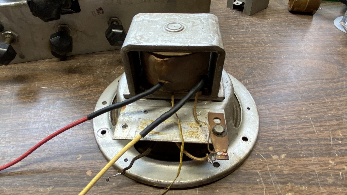
Philco model 610 speaker (type P-27), being modified for use on this 29/45 chassis.
After drilling the hole, I set about the task of lengthening the field coil and voice coil leads. Once that was done, I did one more test fitting, using two screws in front to hold the speaker in place.
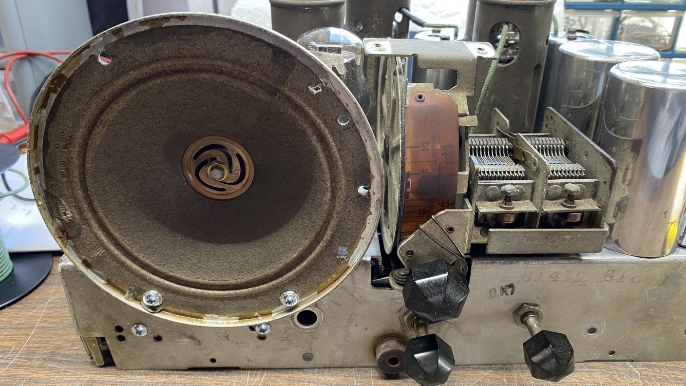
The Philco 610 speaker (P-27), mounted on the 29/45 chassis.
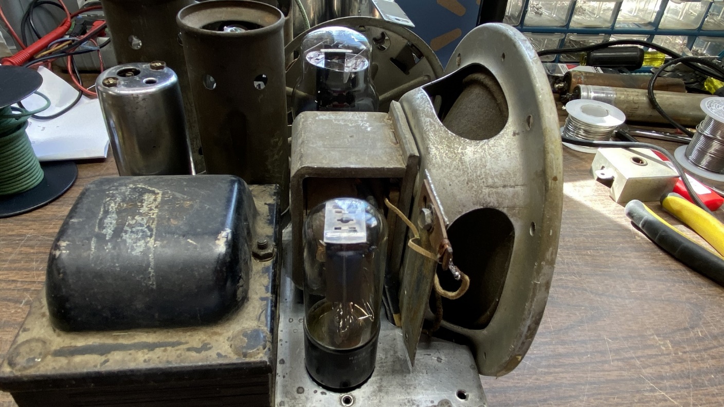
Side view of the 29/45 chassis, with the P-27 speaker mounted in place.
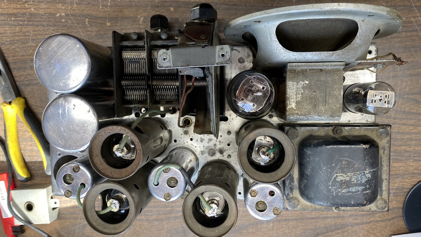
Top view of the 29/45 chassis with the speaker in place.
Even with the metal plate which formerly held the output transformer, the speaker looked fine and it appeared the two mounting screws were going to be quite sufficient to hold it in place.
I also did a test fitting of the output transformer, which I had removed from the speaker. Due to its terminal board, it took up a lot of room under the chassis, but it appeared as if it was going to work out.
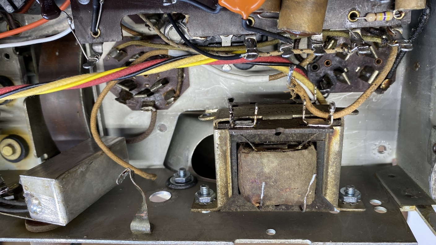
The Philco 610 output transformer, now mounted under the chassis.
And we’ve run out of space again. In the next installment, I will remove the speaker and shorten the wire leads and then reinstall and attach the leads to the audio output transformer under the chassis. This will be followed by reattaching the volume control and the AC line bypass Bakelite block capacitor. And there will be more work to do after that.
Until next time!