I resoldered the tone control wire back onto the metal tab of the tone control. After doing this, the tone control was bolted back onto the chassis. This, of course, was very easy to do as it is held onto the chassis with a single nut and washer.
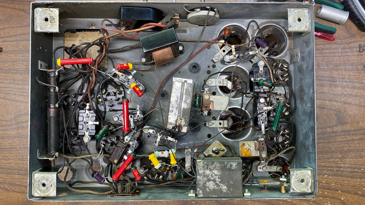
I followed that up with reattaching the two metal can capacitors, parts (24) and (30), back under the chassis, and reattaching each of the six lead wires to their respective places.
The under-chassis work was nearing completion. I decided this would be a good time to reunite the tuning condenser with the chassis.
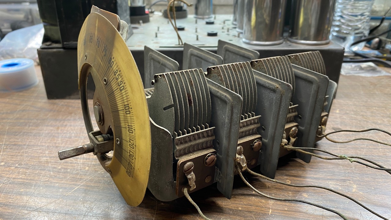
The model 90 tuning condenser. Pay attention to the screws on the sides. See text for details.
Do you see those multiple screws on the side of the tuning condenser in the photo above? There are eight on one side, and eight more on the other side. All of them need to be tightened. This is typical of nearly any Philco set made between 1930 and 1932. These screws have worked themselves loose over the multiple decades. If they are not tightened, intermittent operation could result. I have had this very thing happen to me in the past with a model 70 receiver, which is how I learned about this fix.
Once all 16 screws had been tightened, I carefully threaded each of the seven connecting wires through the proper holes on top of the chassis, and placed the tuning condenser into position. Then, the chassis was carefully placed on its side so that I could reattach the mounting bolts. This was a difficult job, and if I had used two piece rubber mounting grommets for the tuning condenser, this job would have been even more difficult. However, with perseverance, the tuning condenser was soon fastened in place on top of the chassis once again.
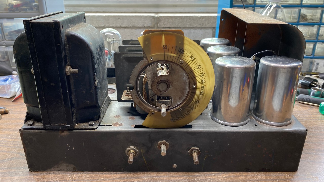
The tuning condenser is mounted on the chassis.
I turned the chassis upside down and resoldered each of the seven wire leads of the tuning condenser to their proper places.
However, I find that I have managed to get ahead of myself. Before the tuning condenser was reinstalled, I decided to clean and polish the RF and IF coil shield cans to the best of my ability. Using some Mothers Mag & Aluminum Polish and elbow grease, this task was achieved in a reasonable amount of time. As you may see in the photo above, those coil shields are now shiny once again.
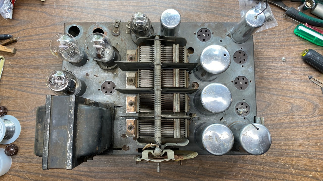
Top view of the chassis showing the tuning condenser back in place, alongside freshly polished coil shields.
I should also mention that I had previously tested the tubes. Of the nine tubes used in this set, four were bad, four were good, and one was not the proper tube. Someone had placed either a 36 or a 39/44 (the tube number was no longer readable) in place of one of the 24 tubes.
This is why you see only four tubes in the photo above. I plan to go through my tube stash and, if possible, populate this chassis with an entire set of globe shaped tubes as would have been originally used in 1931. But that will be one of the last things I do to this chassis before I try it out. We are not quite ready for that yet.
With nearly all of the chassis work now complete, I turned my attention to the electrolytic capacitor cans. As I have mentioned in a previous installment of this model 90 restoration series, Philco radios built during the 1931-32 season used mainly copper Mershon brand electrolytic capacitors, with some models leaving the factory with Sprague electrolytics instead. The Spragues are made of nickel-plated copper, but otherwise look similar to the Mershon units.
You may recall that the two electrolytics in this radio had been replaced at some point with aluminum electrolytic capacitors. For the sake of appearance, I wanted to put Mershons back into this set, but the only ones I had were two 8 uF units. Originally, 6 uF electrolytics were used in models 50, 70, 90, and late model 112 Philcos. The 8 uF electrolytics look very similar to the 6 uF units, but they are about an inch taller than the originals. Most people will not know the difference when looking at the back of the chassis once the set is complete.
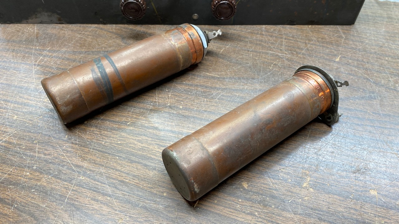
A pair of 8 uF Mershon electrolytic capacitor cans.
While it is not an easy job, these Mershon electrolytics can be rebuilt. I would like to show you my technique for doing this work.
First of all, the bottom lip of each can must be cut off. I did this carefully, using my Ryobi “Dremel” tool and a cutting wheel, so that I could reattach the bottom lips once the job was complete if I wished to do so. I did the cutting work outdoors to avoid breathing copper dust.
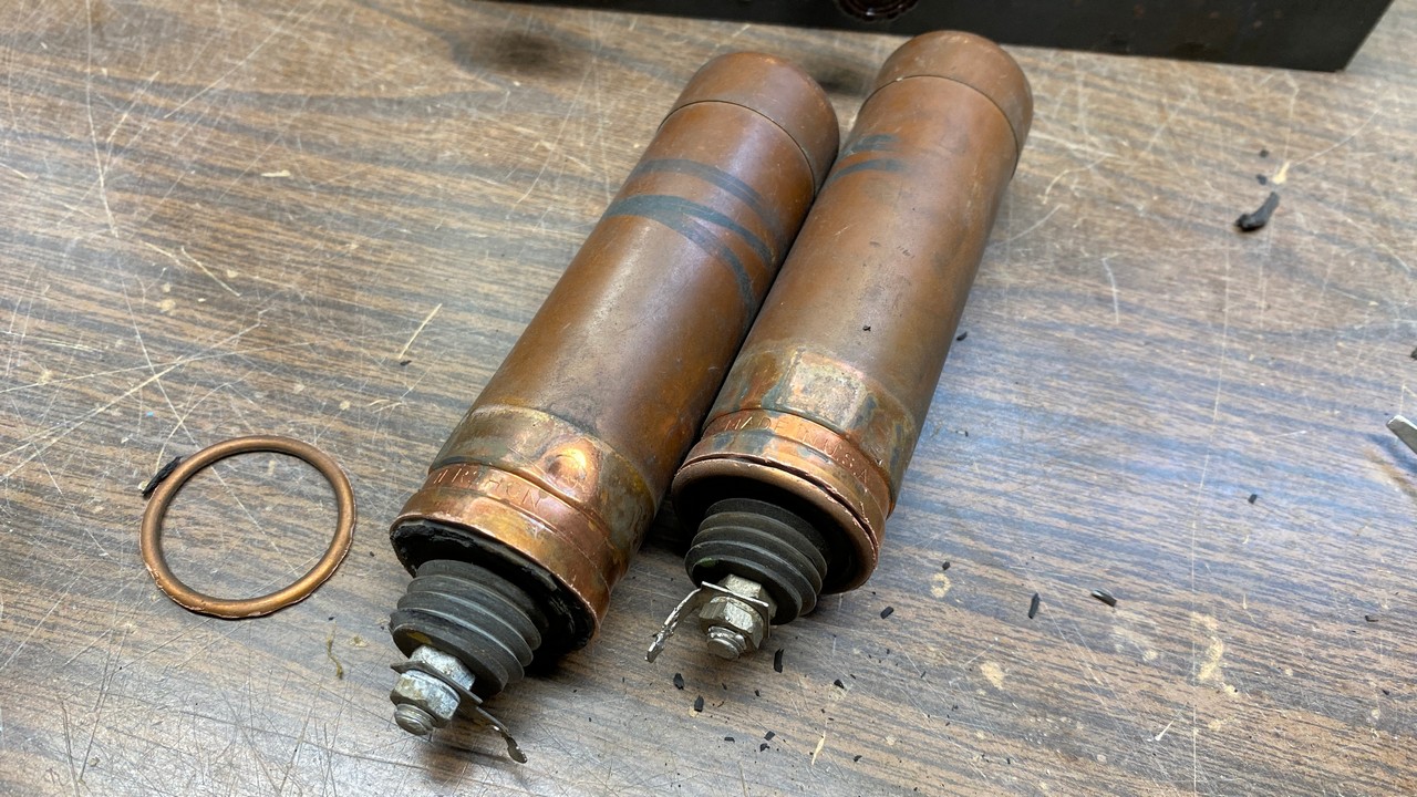
The two Mershons, with bottom lips cut away, ready to be opened up.
I carefully pried away the lip of one of the cans and set it aside for safe keeping.
Next, the old rubber seal has to be cut away. This involves going around the base of the electrolytic and cutting away as much of the old rubber as possible with a sharp knife.
Be very careful if you try this at home, as you could be easily cut with the knife.
Cutting away the rubber seal from the bottom of one of the old electrolytic cans.
Once I had cut the rubber seal away from the bakelite base and the surrounding copper, I tried to remove the bakelite base. It would not budge. I tried multiple times to remove the base, but it was stuck on there good and proper!
At this point, I moved on to the other can and repeated the process of removing and saving the lower lip, and then cutting away the rubber seal.
This time, the bakelite base easily pulled free of the can as may be seen below.
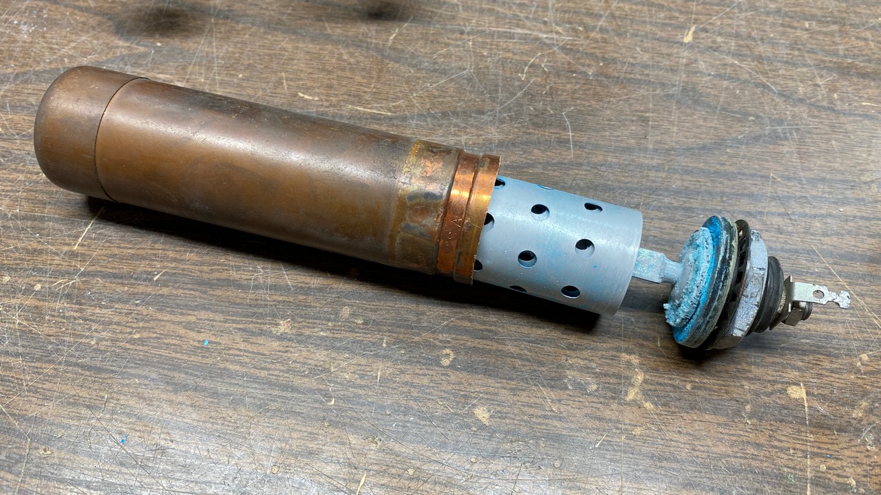
Opening up one of the Mershons.
I removed all the hardware from the center stud of the electrolytic and then tapped on the stud to loosen it from the bakelite base. Then, I pulled the assembly out of the old can and removed the bakelite base from the center stud.
At this point, things looked as shown below.
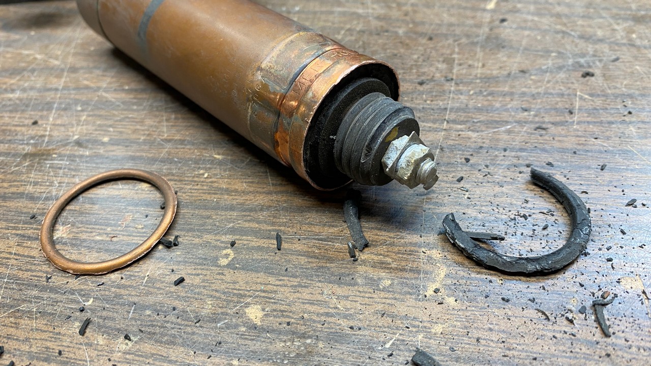
The old Mershon condenser can has now been separated into its individual parts.
The old capacitor body, with its aluminum center stud, found a new home in the trash can. I will clean up the bakelite base and the inside of the copper can later, prior to installing a new capacitor inside the can.
As for the other can with the stuck bakelite base, I wasn’t sure how to handle freeing the base from the can. I decided to fill the gap underneath with PB Blaster, hoping that the spray product would wick into the microscopic space between the can and the base and allow me to free it in a day or two.
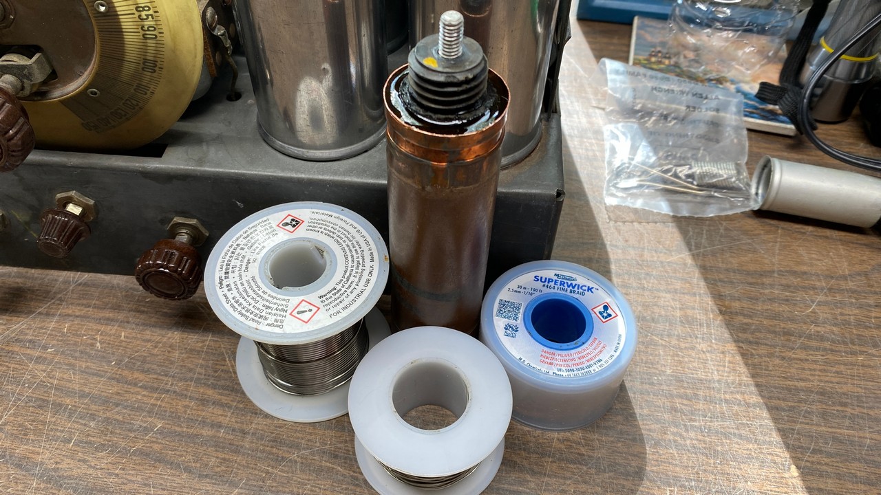
The stubborn can with PB Blaster.
Well, you guessed it – we have run out of space once again. This is a good time to walk away and let that PB Blaster soak in and, hopefully, allow that stubborn bakelite base to be (eventually) removed from the can. Next time, I will let you know what happened.