Last time, I had finished rebuilding the 37-116 RF unit which I hope to use either as a “standby” RF unit for the 38-690 or if necessary, as the replacement RF unit for this radio. My next step is to try out the newly rebuilt RF unit and make sure it actually works.
I made the decision to use a 37-116 chassis as a test jig or test bed to try out the RF unit and see if it works. This way in case there are issues with the rebuilt RF unit, it will not damage the 38-690’s circuitry.
This may seem like taking the long way – a very long way – around an issue. However, there is a method to my madness. Or is that a madness to my method? Regardless, I wish to be extremely cautious in my approach to this 38-690 problem. The goal is to send it back home properly repaired – and never see it here again. Towards that end, I have been working with an overabundance of caution, in order to try and get this all right the first time.
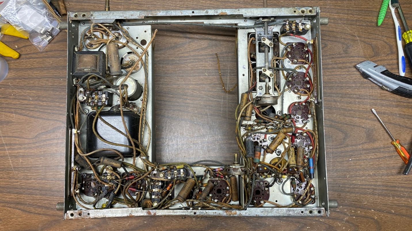
Underside of the proposed test jig – an old Philco 38-116 chassis.
I have a fairly clean, restorable 37-116 chassis which is missing its dial scale but appears to have everything else including another RF unit. But until today, I had overlooked a 38-116 chassis I had which does not have an RF unit. This chassis may have been the one which furnished its RF unit to the 38-690 to begin with. I am not certain of that now. In any event, since the RF unit was already gone, I decided that this would be the chassis which I would use as my test jig.
I began by removing all components in the power supply and audio sections since I would not be using these.
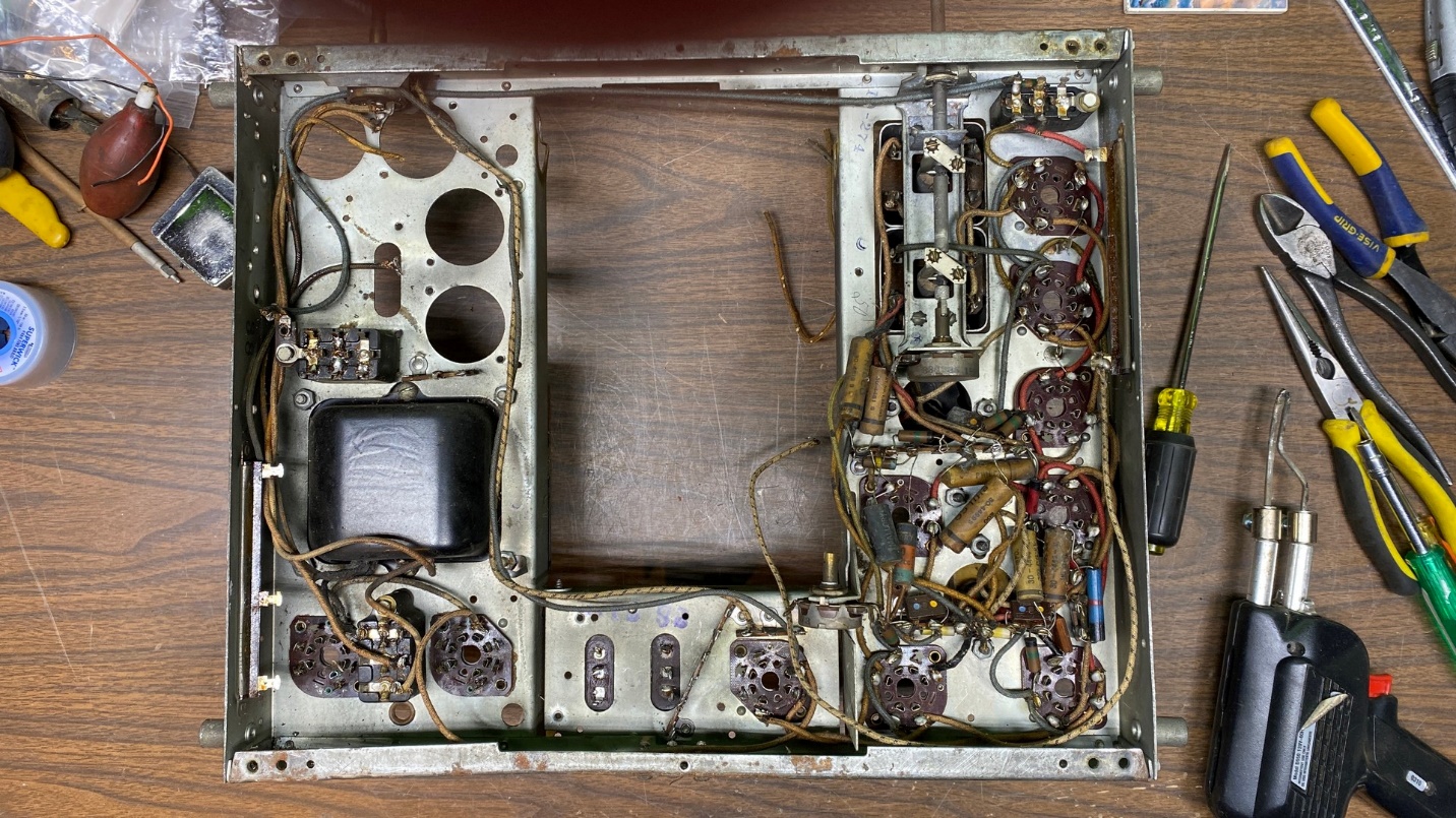
After removing most of the components in the power supply and audio sections of the 38-116 chassis.
But before I go too far in doing this, I need to stop and map out a plan of attack. I will show you just what I have in mind…next time.