Before proceeding to partially disassemble this Philco 38-116 chassis in order to partially rebuild it as a test jig for Philco RF units, I felt that I really needed to draw out what I wanted to do.
I began with a stock Philco 38-116 Code 121 schematic. The 38-116 Code 121 was originally made for use with the 37-116 RF unit. See below.
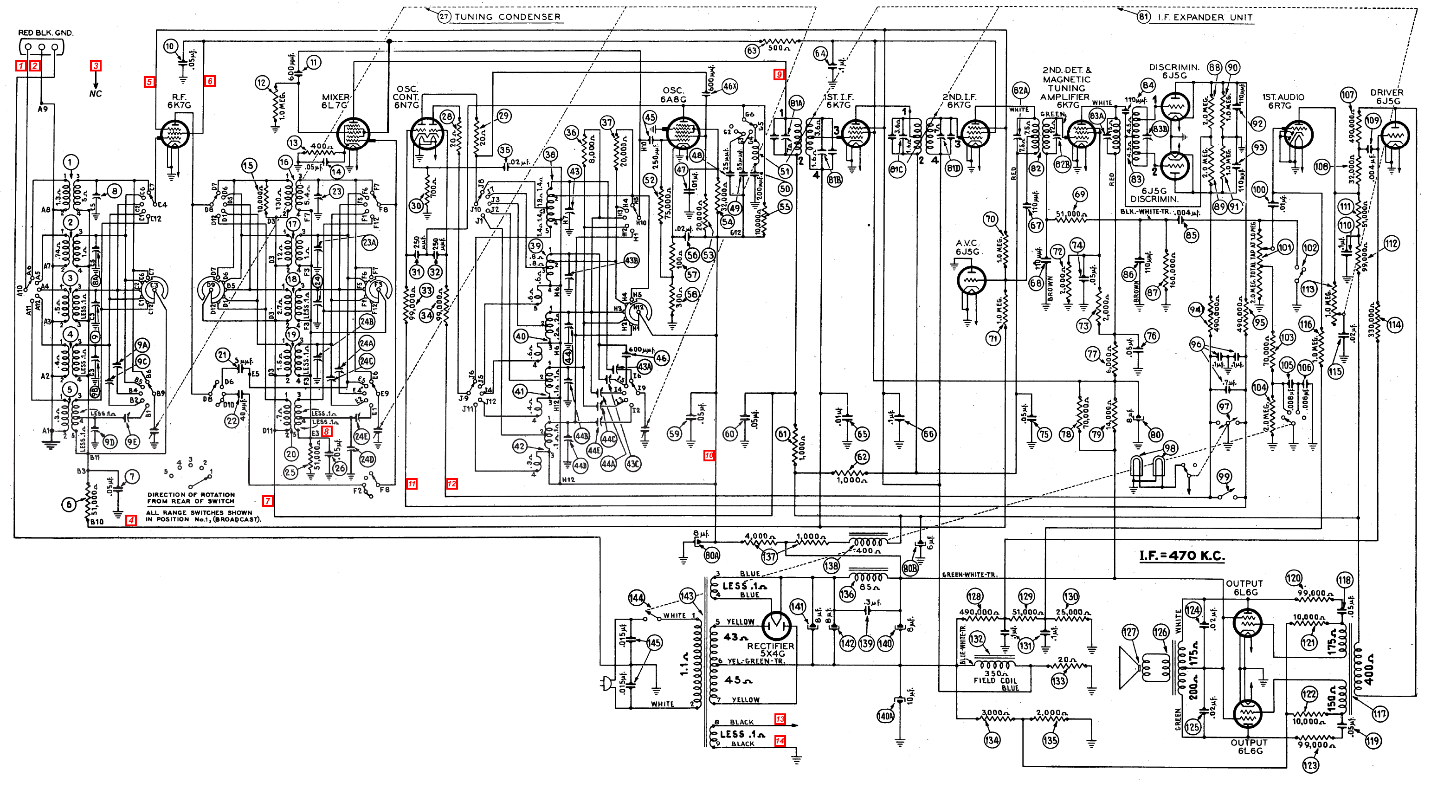
Stock Philco 38-116 Code 121 schematic. Click to see an enlarged version.
Using my old standby paint program – a 24-year-old version of Paint Shop Pro, Version 4.14 – I began to make changes to the 38-116-121 schematic, highlighting portions of the schematic I would not be using for the test jig. When finished, it looked as it does below.
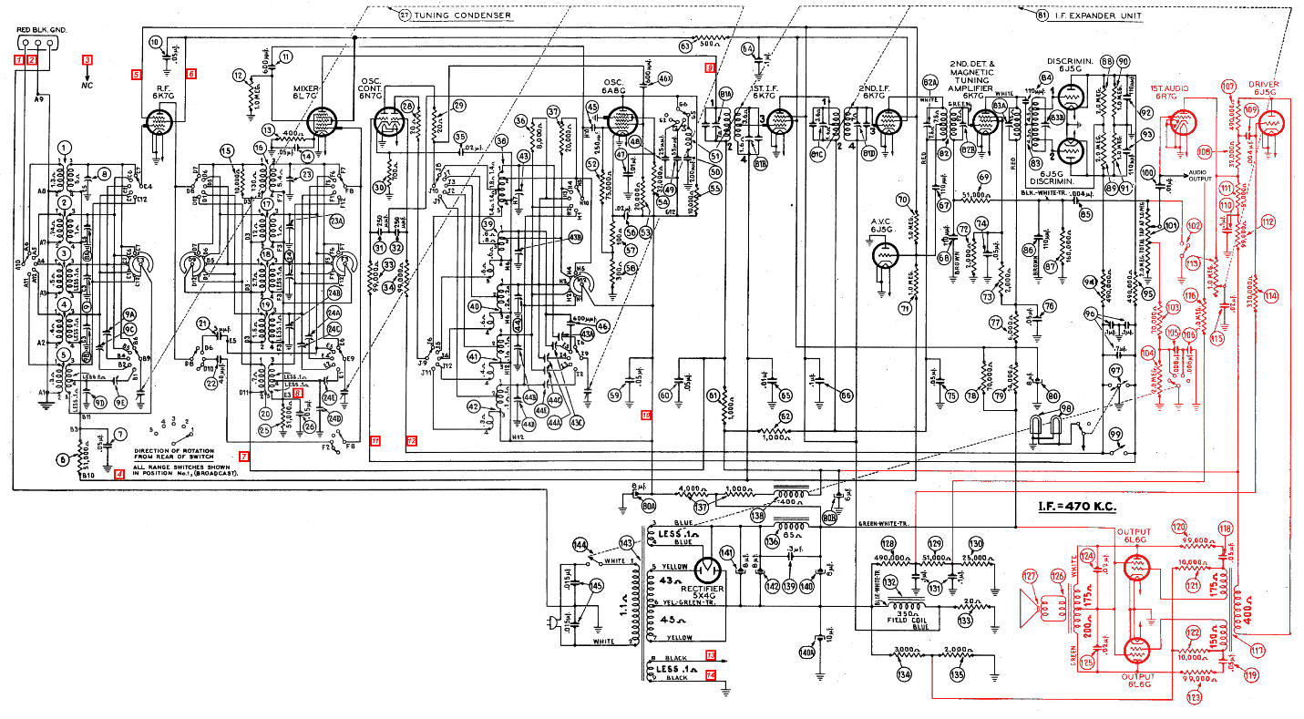
Philco 38-116 Code 121 schematic, with my proposed modifications. Portions of the circuitry I will not be using is in red. Click to see an enlarged version.
As you will see by looking over my modified schematic, I intend to take off the audio signal at the radio’s volume control. Therefore I will not be using the audio preamp or output circuitry, and will also not need the set’s speaker (I do not have one anyway). I will have to come up with a substitute for the 350 ohm speaker field coil, but that will be simple – I will use a power resistor instead.
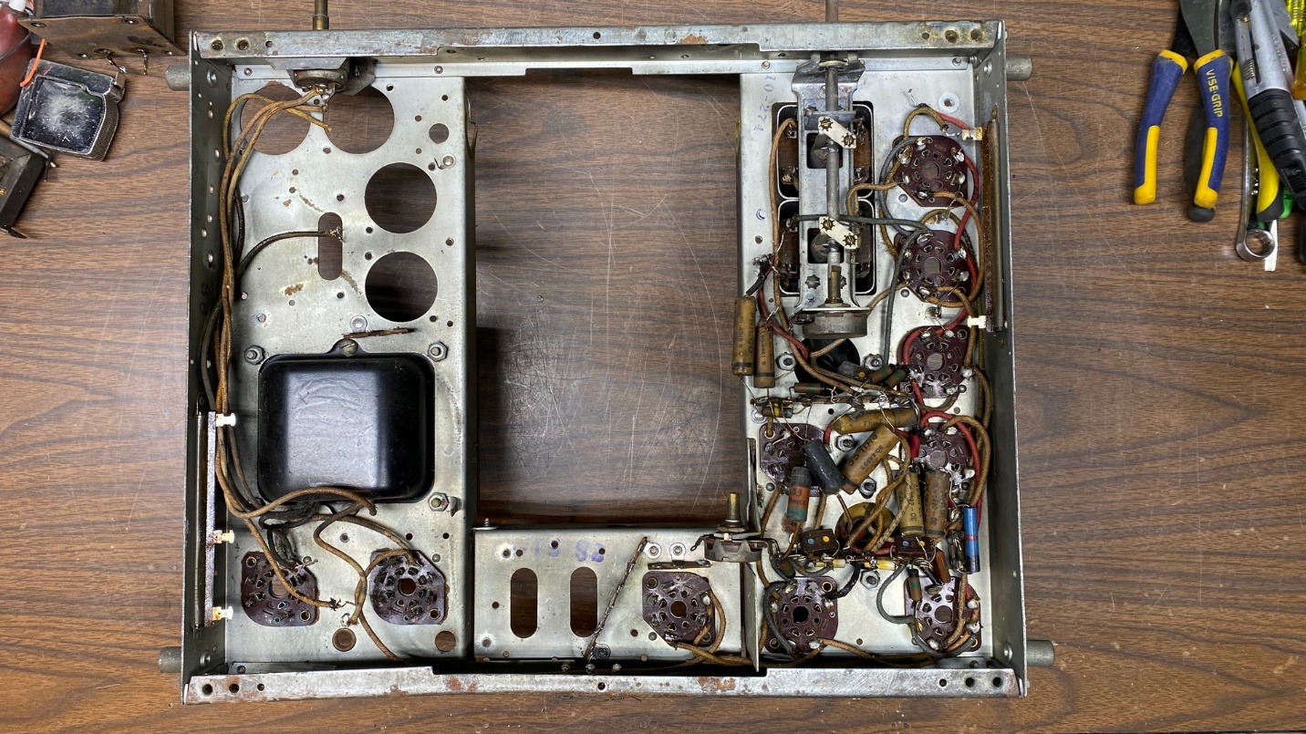
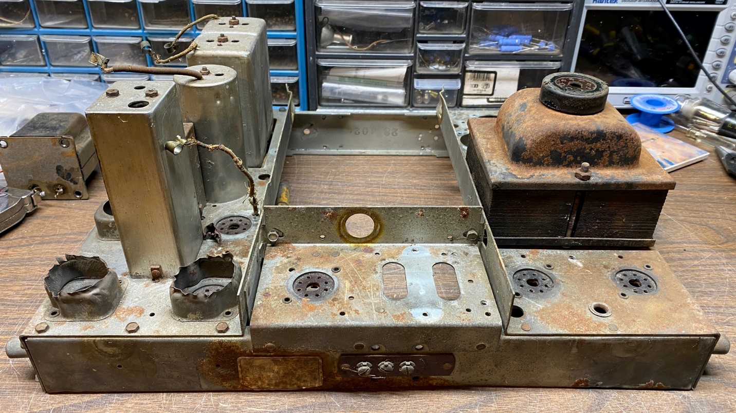
Philco 38-116-121 chassis, now ready for a partial rebuild.
Now, with my new schematic, I proceeded to remove a few more components from the chassis. It is now ready to be rebuilt.
In my next installment, I will start rebuilding the chassis and begin getting it ready for use as a test jig for Philco RF units.