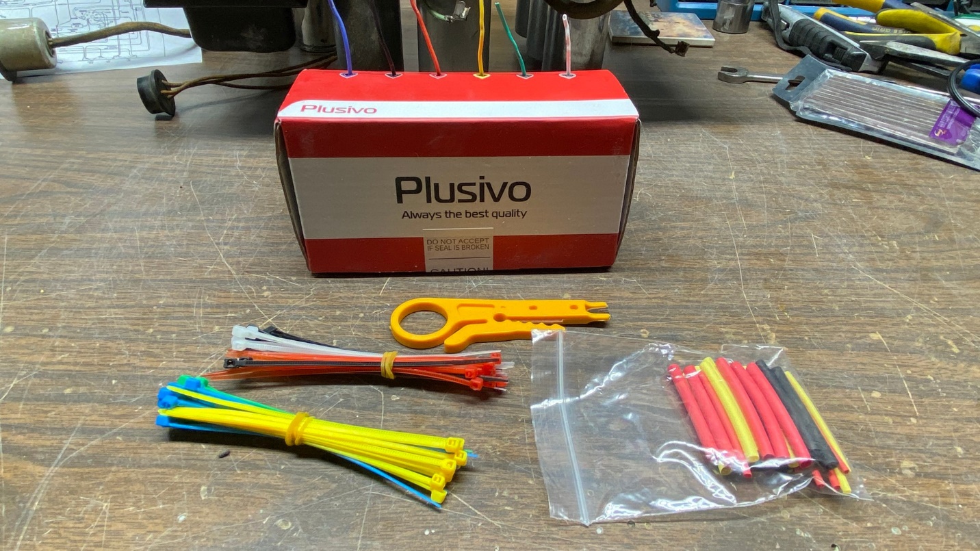
After much online searching, I finally found a source of 20 gauge PVC insulated wire – from Amazon, of all places. The kit contains six rolls of various colors of wire, each roll only holding approximately 20 feet each. No, that isn’t a lot, but it should be plenty for one or two radio rewiring jobs.
As you can see in the photo above, the kit also comes with wire ties and small pieces of heat shrink tubing in colors to match the six colors of wire.
This wire allegedly has insulation rated at 600 volts. However, upon receiving the kit, it seems to me that the thickness of the insulation is no greater than that of 20 gauge wire with 300 volt rated insulation.
But since I now had the wire, I decided I would go ahead and use it. For the time being, though, I turned my attention to the electrolytic capacitors.
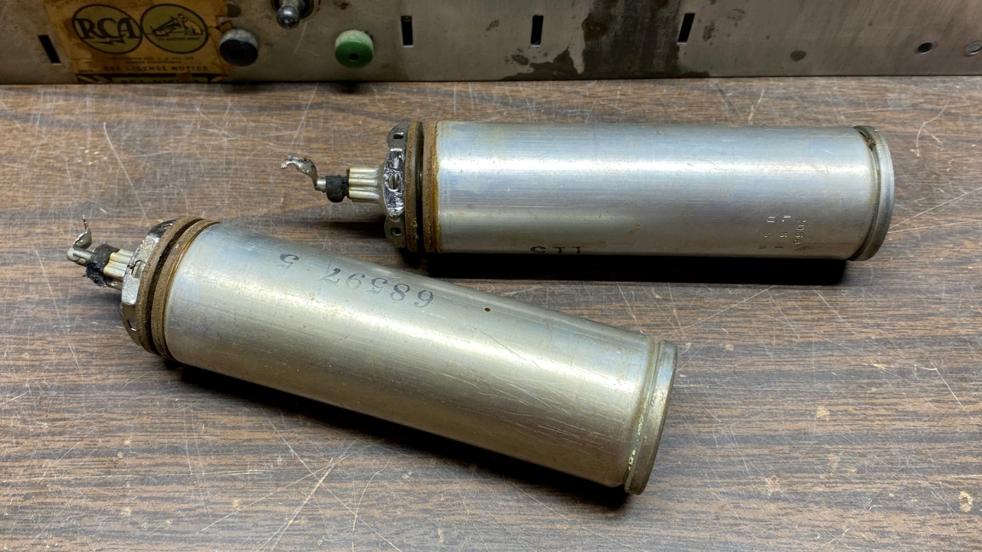
The electrolytic capacitors as they appeared prior to restuffing.
I was very fortunate in that the original wet aluminum electrolytic capacitor cans had been left in place. These had been disconnected from the radio’s circuitry at some point and replaced under the chassis with smaller tubular electrolytics.
So many times over the years, I have seen radios which have had their original electrolytic cans missing. In my younger years, I did not give this too much thought. But once I learned how to restuff old aluminum electrolytic capacitors, I now prefer to have these in the radio. They are not that difficult to restuff, and reusing them preserves the original appearance of the set.
I will now show you some of the steps I go through in restuffing these cans.
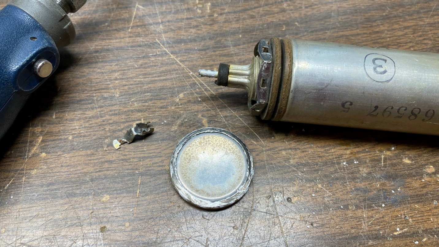
The 10 uF electrolytic capacitor now has its positive connector removed. I have also cut off the top of the can.
In the previous photo, you may have noticed that each of the two electrolytic cans have a crimped seam near the top. This is a convenient point for cutting the can open. You may use a Dremel tool with cutting wheel, a hacksaw, or a tubing cutter for this purpose.
Once you have cut off the top of the can, don’t lose it. You will glue it back into place when you have finished restuffing the can.
Normally, I have to struggle a bit to get the positive terminal free from the aluminum rod at the bottom of the can. But in this instance, the crimp was already loose and so the connector was easily pulled off.
You may see these parts in the photo above.
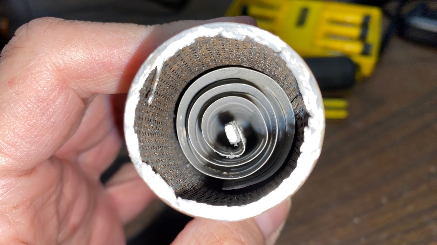
Interior of the old 10 uF electrolytic can.
Now let’s look inside the can. This can was originally filled with a boric acid solution which acted as the electrolyte. The solution can leak out or dry out over the decades, usually leaving a white powdery residue inside.
I have cut cans open which still had liquid electrolyte inside. The boric acid will not harm you if you get it on your skin, but it is toxic if ingested. Its key ingredient is borax, the same material as used in 20 Mule Team Borax – yes, that laundry detergent is still being made and sold today.
Anyway…
The thing to do at this point is to remove the inner (positive) electrode. This is the aluminum rod at the center of the can, along with the aluminum plate which is curled around the rod.
You need to be sure you have removed the terminal from the bottom of the can, which is attached to this same aluminum rod. Normally, I cut off the end of the aluminum rod just above the point where the positive terminal is crimped in place. But as I mentioned earlier, the positive terminal was already loose so I merely pulled it off the rod.
Now, using a pair of large, extra long needle-nose pliers, it is a simple matter of reaching into the top of the can, grabbing the aluminum rod with the end of the needle-nose pliers, and pulling the positive electrode out of the can. This will require some twisting as well as turning, but is not difficult to do.
Removing the positive electrode from the can.
Once you have removed the positive electrode from the can, you will be left with a collection of parts as shown below.
A disassembled 10 uF electrolytic can.
The old positive electrode may be disposed of at this point as it is no longer needed.
I should mention that there is also a thin plastic insulator inside the can, wrapped around the inner wall of the can. I like to leave this in place to keep the new wiring from possibly touching the inner wall of the can.
The can has been prepared for a new copper rod (positive terminal) and a small hole for the negative lead.
Now the can must be prepared for the new capacitor to be installed inside.
I use 10 gauge solid THHN electrical wire as my new center (positive) electrode, leaving its outer insulation in place to give the copper wire extra protection from the center hole where it passes through to the outside of the can. To make this wire fit, I carefully drill out the center hole where the old, dried-out rubber insulator is, with a drill bit of the appropriate size to ensure the 10 gauge wire will have a slightly loose fit.
Using a smaller drill bit, I also drill a hole between the threaded portion of the can and the center hole of the can, as seen above. This hole is for the negative lead of the new capacitor. Since we cannot solder copper to aluminum without special solder, and since I prefer not to even try doing this, a separate wire for the negative lead is necessary. This wire will (eventually) be soldered to the attaching nut of the can.
A new 10 uF Solen Fast capacitor is about to be installed inside the old can.
There is a series of film capacitors, manufactured by Solen and available from Antique Electronic Supply, which is ideal for restuffing certain aluminum electrolytic capacitor cans. While somewhat large, the 10 uF, 630V size will fit inside one of these 1-3/8 inch diameter aluminum cans.
Since these capacitors are wrapped film instead of electrolytic, they should last much, much longer than any new electrolytic capacitors would in this application. And since they are film capacitors, they have no polarity; therefore, either lead can be the positive lead and the other will be the negative lead.
The new positive electrode (10 gauge insulated wire) needs to be fed into the center hole of the can and pushed out to the other end. Now, this end of the wire is stripped and one lead of the new Solen capacitor is soldered to it. I like to double insulate this soldered joint with two pieces of heat shrink tubing for safety.
For the new negative lead, I feed a smaller insulated wire (20 or 22 gauge will do) through the smaller drilled hole and up through the top end. The end of this wire is likewise then stripped, and then the other lead of the Solen capacitor is soldered to this smaller wire. Again, I use two pieces of heat shrink tubing to cover the soldered joint.
Once the wires are soldered and heat shrink applied, the capacitor may be carefully pushed and/or pulled into the capacitor can.
Cut off the 10 gauge copper wire so that only about ½ to ¾ of an inch of the wire is sticking out from the bottom of the can. You may apply a small amount of J-B Weld around the point where the new wire protrudes through the outside of the center hole to hold this wire in place.
Also, cut off all but a few inches of the small wire which will serve as the negative lead, and strip away all but about an inch or so of its insulation. You want this wire to be longer as you cannot tell exactly how long it will need to be until the can is attached to the chassis again and tightened in place with its associated nut. It is then that the negative wire will be soldered to the nut, and the excess wire cut off.
Here, I sort of lost myself in restuffing the other electrolytic and then attaching both to the chassis, so I did not take any other pictures of these. But to finish up describing my restuffing technique, I will use a photo from a previous restoration job.
A restuffed electrolytic capacitor can.
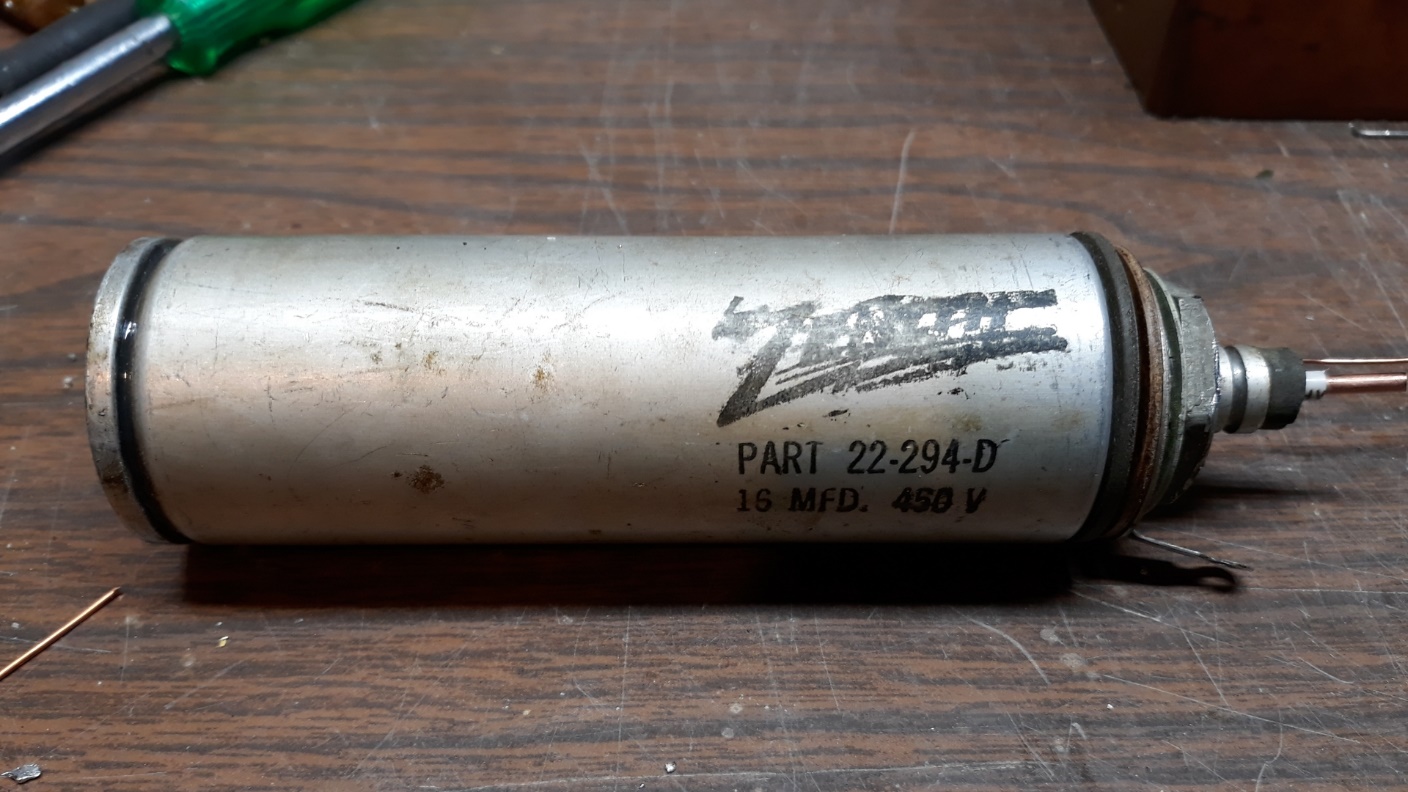
The above photo shows an electrolytic from a 6-tube 1937 Zenith radio which I restored four years ago.
Once everything is in place as it should be, reattach the top of the can to the can body with J-B Weld. Crimp, and then solder, the positive terminal to the bottom end of the new 10 gauge copper wire (positive terminal not shown above). Polish the outside of the can with Mothers Mag & Aluminum Polish if desired. The can is now ready for reinstallation into the radio chassis.
Once the can is back in the chassis and tightened into place, you may then solder the negative wire to the attaching nut. You will notice on these RCA sets that the nut is made of thin metal and has slots in its sides; the slots are for attaching and soldering wires. (The Zenith capacitor above has a separate negative terminal and its attaching nut is solid.)
Don’t forget to reuse the insulators originally used to isolate the capacitor can from the chassis; one on the top of the chassis, and one underneath. These are important! The can of the capacitor should not be touching the chassis at all if these insulators were originally used.
And with that, we are out of space again so I will continue with the T9-10 rebuild in the next installment.