Last time, I went into great detail showing how I usually handle restuffing the Philco multi-section metal can capacitors. As you recall, I did get the can with three 0.25 uF capacitors rebuilt.
Now it was time to rebuild part (30), which contains one each of the following capacitor values: 0.1, 0.25, and 1.0 uF.
Remember, most Philco service data gives the wrong values for the part (30) metal can. This error is documented here on the Philcoradio.com website.
Removing the old capacitor block was done in the same manner as with the part (24) can which I rebuilt in the previous installment of this series. There was only one problem – initially the insides of the can would not push out. I ended up having to use some persuasion by way of my trusty heat gun, to loosen the insides enough so they could be easily pushed out.
The paper wrap was then carefully removed from the wax-encased capacitor assembly and set aside while I prepared new capacitors for use inside this can.
I did not have any 1.0 uF film capacitors, so I ended up using two 0.47 uF capacitors in parallel. This would yield a total capacity of 0.94 uF, which would be close enough. I also used my last 0.1 uF capacitor, along with a 0.22 uF capacitor to replace the original 0.25 uF part.
The new capacitors were put together, hot glue was used to hold them together, and wires were attached as appropriate to the ends of the new assembly.
New capacitors were now ready to be placed into the original metal can.
I put the insulating paper back into the can. When doing a test fit of the new capacitors into the can, I could not help but notice that there was a great deal of empty space left inside the can.
For this can, I decided to use hot glue sticks to take up most of the empty space, with just enough melted hot glue to hold the assembly all together inside the can.
The new capacitors, surrounded by unmelted hot glue sticks as well as some melted hot glue, are now in place inside the metal can.
Once this was done, the original wires were run through the hole in the fiber insulator and the insulator was put into place. I finished by folding the four metal tabs over to hold everything in place.
The rebuilt part (30) multi-capacitor can.
I set these two cans aside for the time being, as I wanted to have as much room under the chassis as I could get once I was ready to reattach the tuning condenser. My plan was to reattach the two cans after the tuning condenser was back in place. This would not happen for a while yet.
At this point, I resumed restuffing those bakelite block capacitors.
I resumed this work with the AC line bypass capacitor block, which originally contained two 0.015 uF capacitors. Today, it is preferable to use X1/Y2 safety capacitors with a value of 0.01 uF as replacements inside these blocks. The safety capacitors are designed to fail open, avoiding the possibility of a failed capacitor shorting out which would not be a good thing.
However, after I removed the insides of this particular block, I noticed a problem.
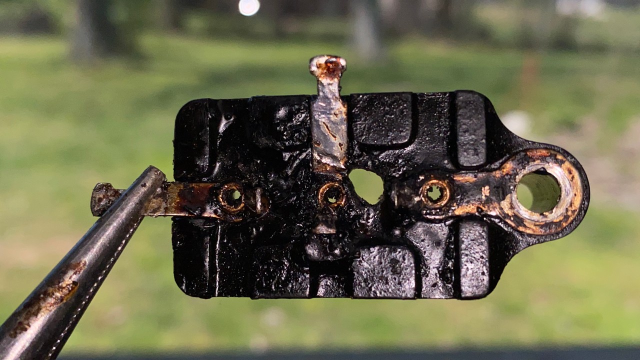
A hole was burned in the top of this bakelite block capacitor.
Look carefully at the photo above. Notice the hole in the block in between two of the block’s terminals? I did not see that before I removed the insides of it. It certainly looked like a hole had been burned in the top of this block. This was not a good thing, and I decided not to reuse this block.
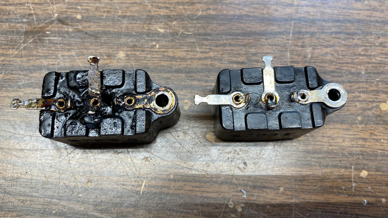
The burned block (left) and a replacement block (right).
I have cleaned out most of my once large stash of extra radio parts. Fortunately for me in this instance, however, I still had just a few Philco bakelite blocks. I had the dual capacitor block which I needed, so I removed the insides from the block I had designated as a replacement.
This time, no surprise burned holes were found, so the new safety capacitors were put into this block and the block was then reattached inside the chassis.
The old, burned block was tossed into the trash.
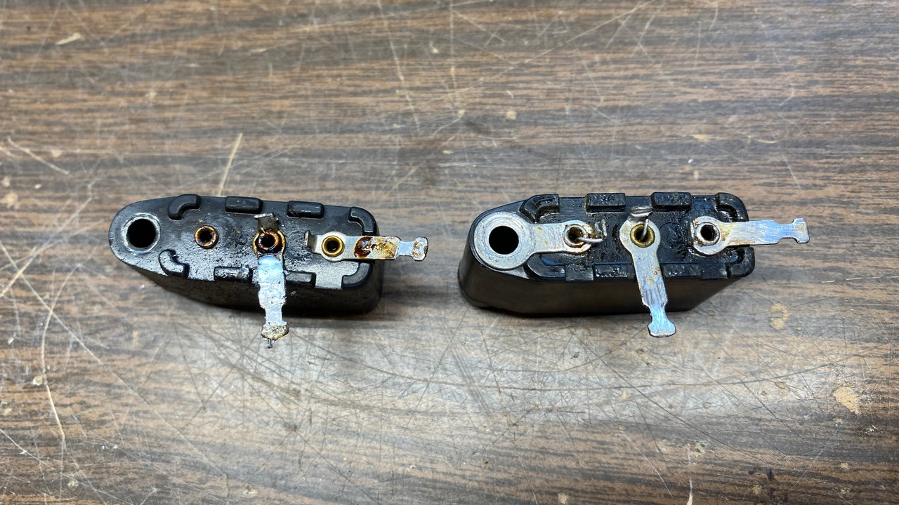
A bakelite block with a missing ground terminal (left) and its replacement (right).
The next bakelite block I wanted to restuff had a missing ground terminal, as may be seen in the photo above. So, once again, I went to the very small stash I have remaining of bakelite blocks and found a suitable replacement.
The replacement block is not the same part number as the original, and its two long terminals were oriented differently than the original. However, when these blocks have had their insides removed, it is easy to bend and turn the terminals as needed. This way, the replacement now looked like the original as may be seen just above.
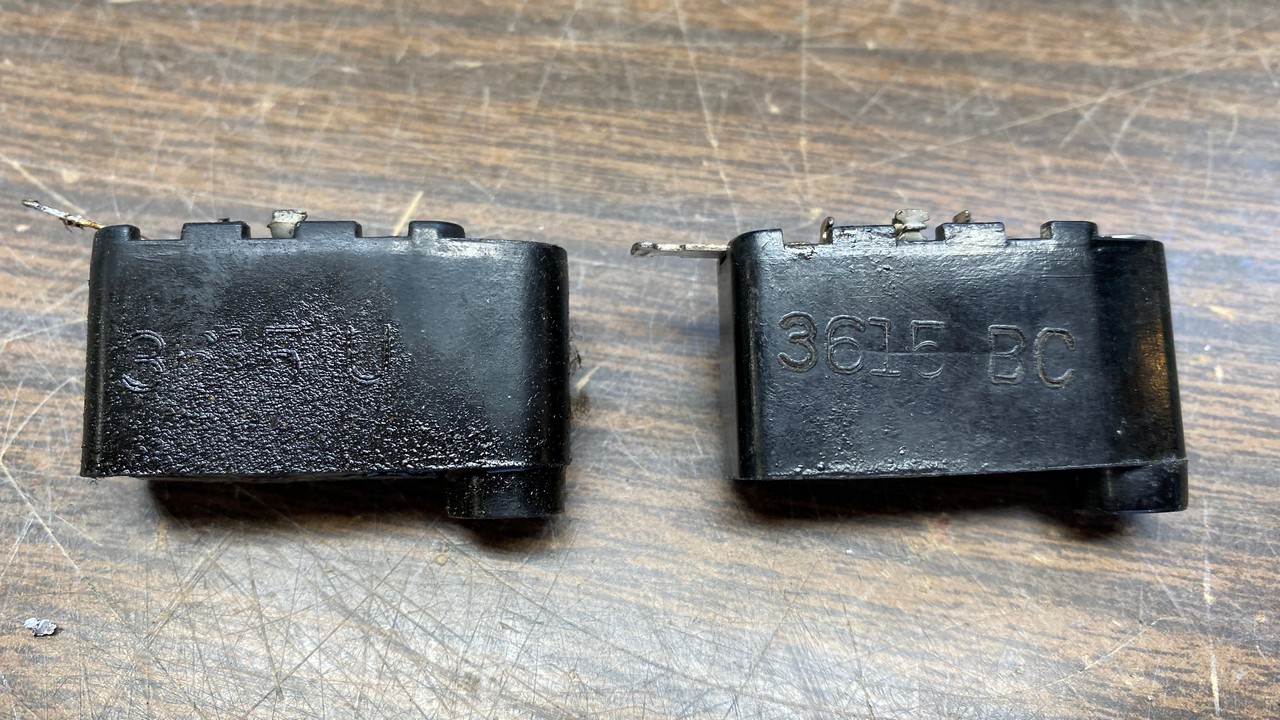
Yet another bakelite block on the left, this time with a terminal that had been cut off, and its replacement on right.
It seemed that I was on a roll, and not the kind of roll that I like. I encountered yet a third problematic bakelite block, this one with a terminal which had been cut off short. This was actually done by multiple repair shops over the decades, as the repairman used a paper capacitor to replace the capacitor(s) inside the bakelite block, and then connected the replacement in any way possible to get the job done.
So, once again, I went to my very small (and dwindling) stash of bakelite blocks, and picked a suitable replacement. The replacement did not have the same part number as the original, so once again, once its insides had been removed, I turned the necessary terminals to make it appear the same as the original part.
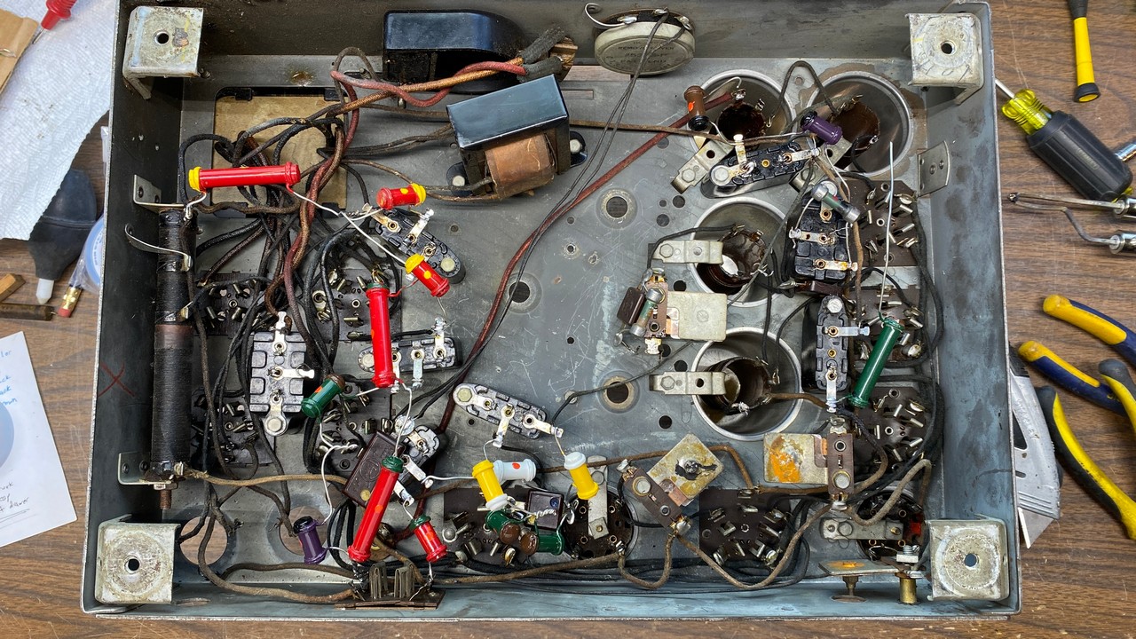
As bakelite block capacitors were rebuilt, new reproduction dogbone resistors were attached under the chassis.
Those three bakelite blocks were the only ones I had to replace, fortunately!
I began to install new reproduction dogbone resistors under the chassis as I rebuilt each bakelite block. Soon, I had rebuilt all but one block and also had most of the new resistors installed.
I had ordered a new supply of 0.1 uF capacitors, and was still waiting for these, so I was unable to rebuild the last bakelite block at this point. Since I am running out of space once again, this is a good point to take a time-out until those new capacitors arrive.
I will continue work on this Philco model 90 in the next installment. Stay tuned!