A parts chassis is purchased – and a surprise.
I needed a working power transformer to complete my Philco model 87. I advertised on two radio forums with no success. Then I noticed a Philco model 83 chassis on the auction site, which was supposedly in working condition. I say “supposedly” because I learned a long time ago to never trust anyone’s word that a radio actually “worked” unless I knew the person really well.
Since no model 87 power transformers were forthcoming, I decided to take a chance and purchase the Philco 83 chassis.
One week later, the chassis arrived at my door.
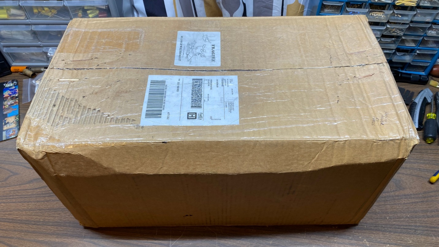
The box which contained a Philco model 83 chassis.
I hauled the 40+ pound box down to our basement where my workbench is located and unpacked the chassis.
It looked just as it had in the auction photos.
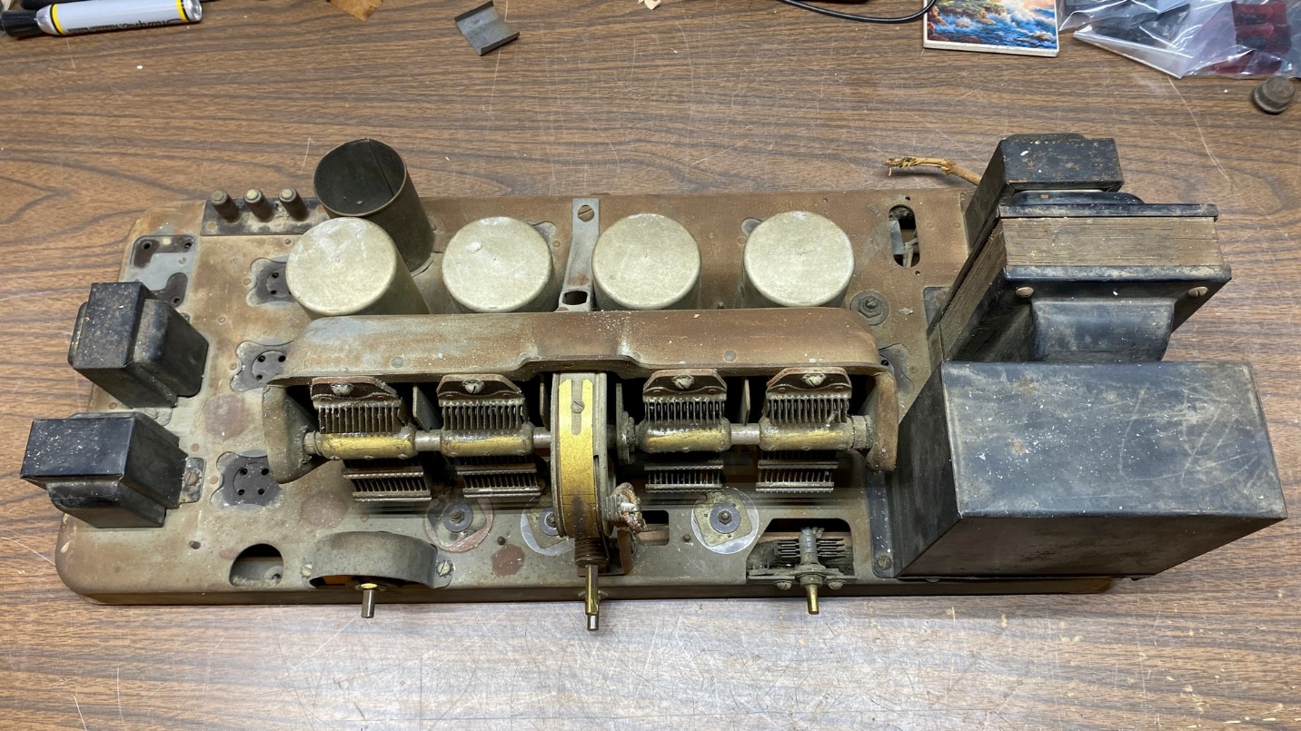
Philco model 83 parts chassis.
Removing the bottom cover, I found a fairly clean underside which appeared to have never been serviced.
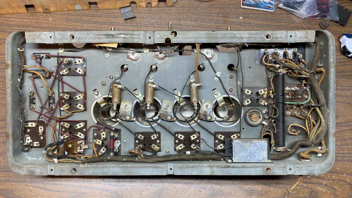
Under-chassis view of the model 83.
But as I looked the chassis over, I began to notice discrepancies in comparison to the model 87. The first thing I noticed was the lack of filter choke (33). But the chassis appeared to have never had a filter choke installed where part (33) should have gone.
The next oddity was the large resistor, part (35). It had four sections instead of the three sections used in model 87.
I looked up at the filter condenser block, part (31). It had eight terminals instead of 10.
Finally, while looking over the top of the chassis, I noticed “UX 171” stamped where (I thought) the 245 tubes should go.
I have a PDF copy of the Radio College of Canada schematics. Knowing that many older radios sold in Canada were made to run on 25 cycle AC, including model 83, I decided to look at that folder to see if it had a Philco model 83 among its schematics, and to find out if it was different from the 87.
Surprise! Model 83 is slightly different from model 87 – and uses push-pull 71A audio output tubes instead of push-pull 45 tubes!
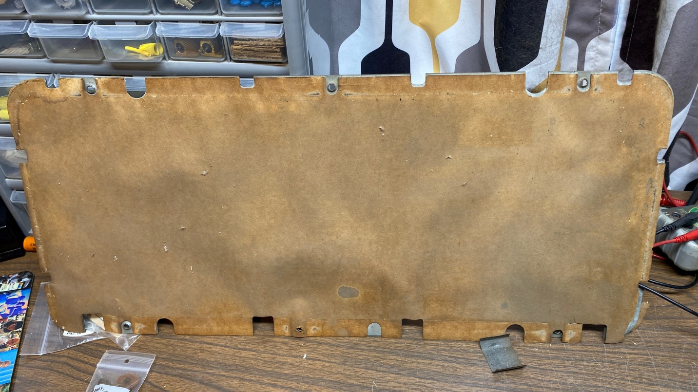
Under the bottom cover of the model 83 chassis was a good paper insulator. I will use this on my model 65.
I then set out to carefully go over the 83 chassis and document the differences. After spending a couple hours at this, I came up with this schematic:
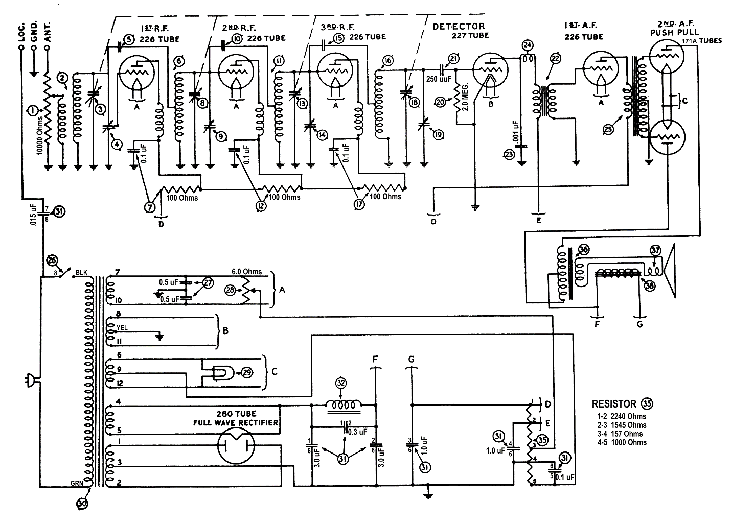
Philco model 83 schematic. Click here for an enlarged version.
I obtained some ideas from the Radio College of Canada schematic for model 83 in drawing out the new schematic shown above, but it was not really clear as to the actual changes between it and model 87. Now, having traced out the wiring in an actual model 83 chassis and documenting these differences in the schematic above, I am now aware of all the changes.
For years – decades, really – I was under the impression that model 83 was the same as model 87, only designed for operation on 25-40 cycle (25-40 Hz) AC current. Now I know there are other differences as well, chief of which are the use of 71A tubes instead of 45s.
I also learned from studying the Radio College of Canada schematics that Philco’s model 62, which I likewise thought was the 25 cycle equivalent of model 65, also uses push-pull 71A output tubes, whereas the 65 uses push-pull 45s.
Is the power transformer good?
I took resistance readings of its windings, beginning with the high voltage primary. It measured 546 ohms across the 80 rectifier plates. So far, so good. From one 80 plate to ground, the measurement was 282.6 ohms. From the other 80 plate to ground, it measured 264.7 ohms. This is a small, acceptable discrepancy. The two halves of the high voltage winding will never be totally equal in resistance due to the way these transformers were wound.
After measuring the remaining windings and feeling fairly confident that I was dealing with a good transformer, I removed it from the chassis.
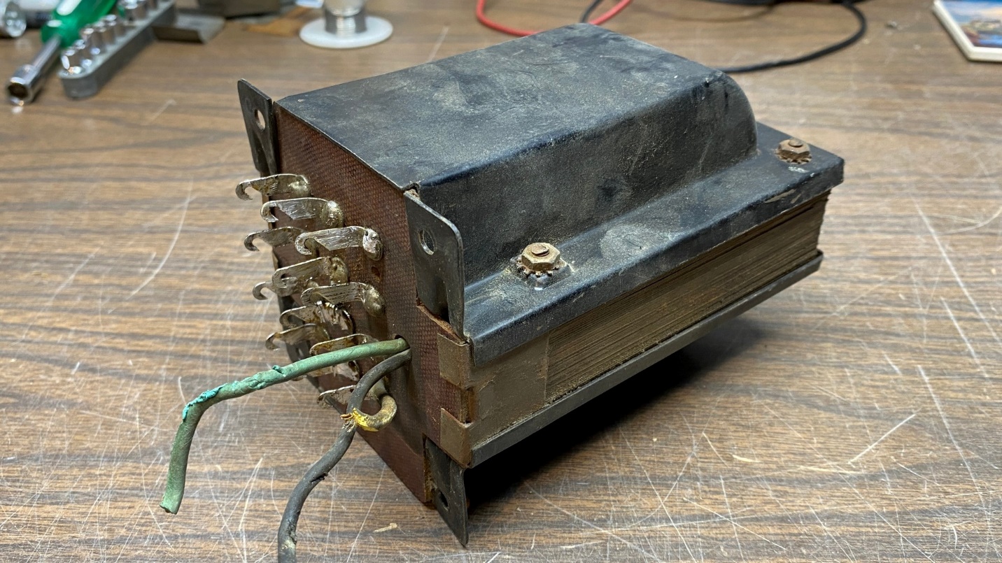
Philco model 83 power transformer.
Oh, by the way, I also measured the windings of filter choke (32) and the two audio interstage transformers, (22) and (25). Choke (32) and both halves of transformer (22) were good! However, the primary of (25) was open. So much for a “working” chassis. But that is not a problem since I bought the chassis for the power transformer.
You may be wondering, What are you going to do now, Ron? Simple – I have a fair amount of money (including shipping) invested in this chassis which I purchased just to get the power transformer. I shall proceed to install the transformer in my 87 chassis and, in effect, convert it into a model 83.
Here is how I propose to do that:
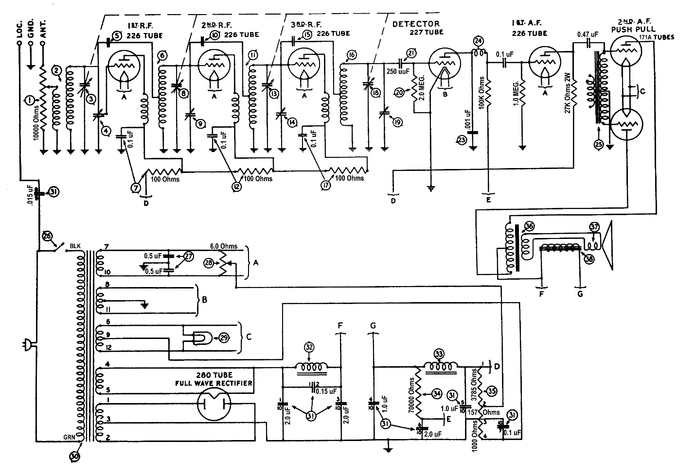
Modified model 87 schematic. Click here for an enlarged version.
Since I already have resistor (35) out of the radio, I will grind off one side of the 640 ohm section with my Ryobi “Dremel” tool, in the same manner as I did with the 3785 ohm section. I will then add a 1000 ohm resistor across terminals 3 and 4 of resistor (35). Since the 71A tubes require a greater bias resistor than the 45 tubes, this modification is necessary.
That is the only modification I will make. As the radio will be operating on 60 cycle (60 Hz) AC current, the filter capacitors I previously installed should be sufficient. I do not expect the extra components in the model 87 power supply – choke (33), resistor (34), 2.0 uF section of the filter condenser block which connects between terminals 6 and 10 of the block – to cause any problems.
And, of course, when the radio is ready to try out, I will install a pair of 71A tubes in the 45 sockets.
That is all for this time. In the next installment I will open the model 83’s power transformer and replace those three wires which have dried-out rubber insulation, put the transformer back together and paint it; after which it will be installed on the 87 chassis. I will also grind off the 640 ohm section of resistor (35) in preparation to add a new 1000 ohm resistor to replace the 640 ohm section.