The previous installment of this series left you with a cliffhanger – Will I be able to successfully reassemble the antenna subassembly?
Let’s find out!
To begin, you do not want to undertake a project of this magnitude without a road map. Or, in this case, multiple road maps. As a matter of fact, I have no less than seven road maps (or keys if you will) to help me get this subassembly properly reassembled.
Here is the first road map I am using:
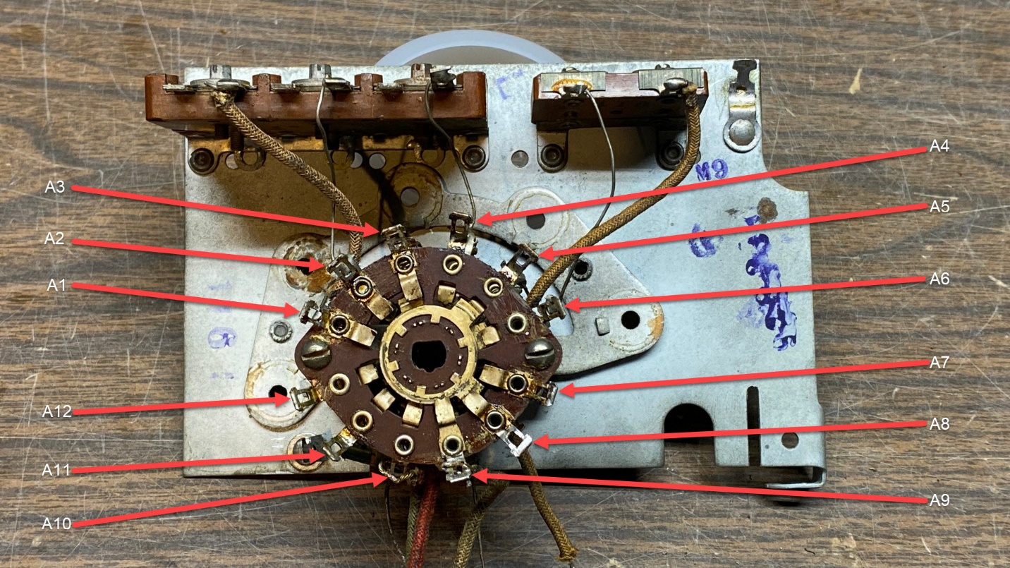
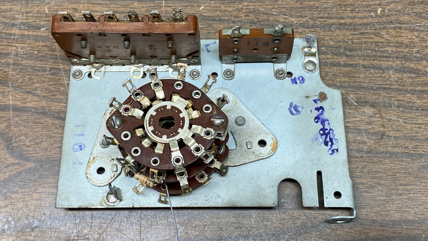
Showing which terminal is which on wafer A of the antenna subassembly
The photo above clearly illustrates which terminal is which on wafer A of the antenna subassembly. Terminal A1 had the dab of red nail polish on it, and as you can see, the terminals advance clockwise from there. This will be helpful when it comes time to start resoldering wire leads, resistors, capacitors, and coil leads to the various terminals.
This key does not show wafers B or C, but their terminals are numbered in a similar fashion. If you have the 37-116 schematic, you will notice that these terminal numbers match those on the schematic.
Did I say multiple road maps?
Yes – there are more:
Switches
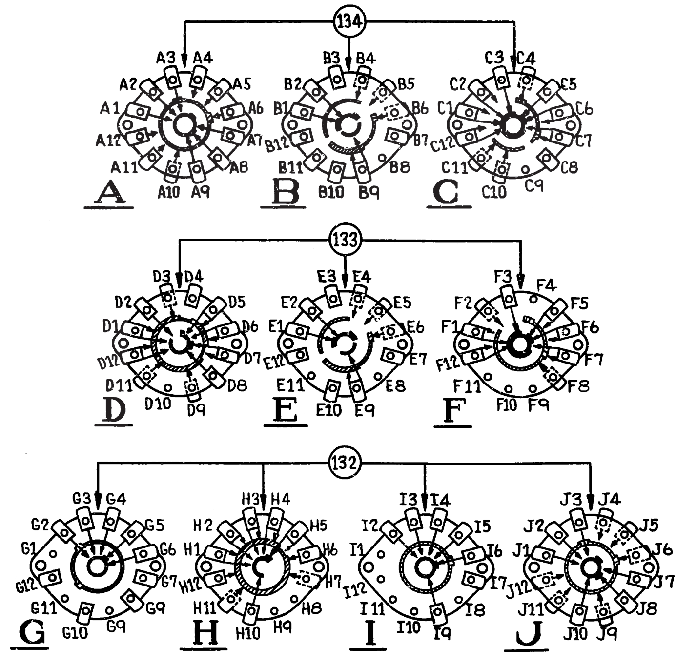
The ten switch wafers used in the 37-116 RF unit. For now, we are only concerned with wafers A, B & C.
Coils
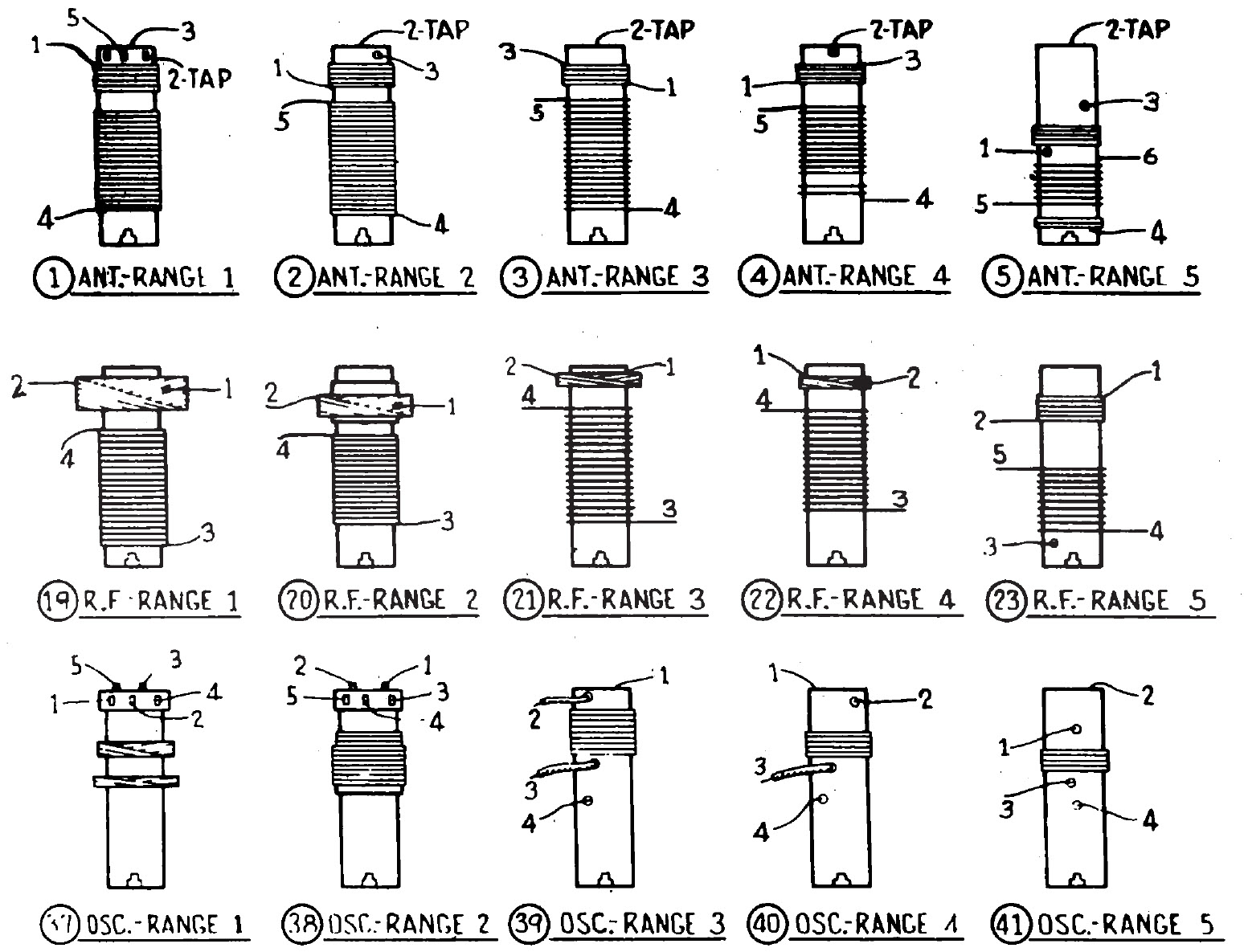
The various coils used in the 37-116 RF unit. The section I am working now uses the five coils in the top row above.
Trimmer Capacitors
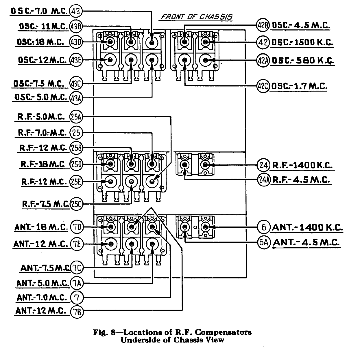
The trimmer capacitors of the 37-116 RF unit. The section I am working on uses the trimmers with the “ANT” prefix.
Partial Schematic – Antenna Subassembly
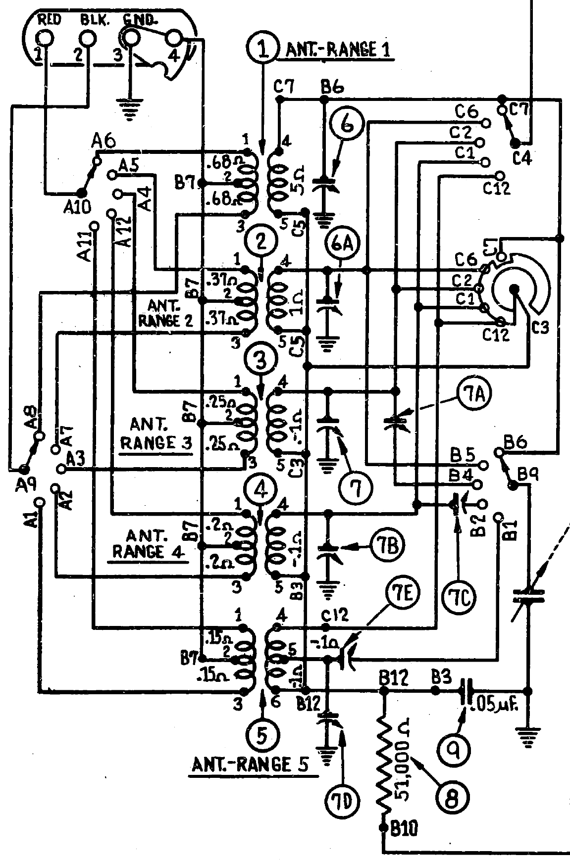
Partial schematic showing the antenna subassembly
Partial Schematic – Converter Subassembly
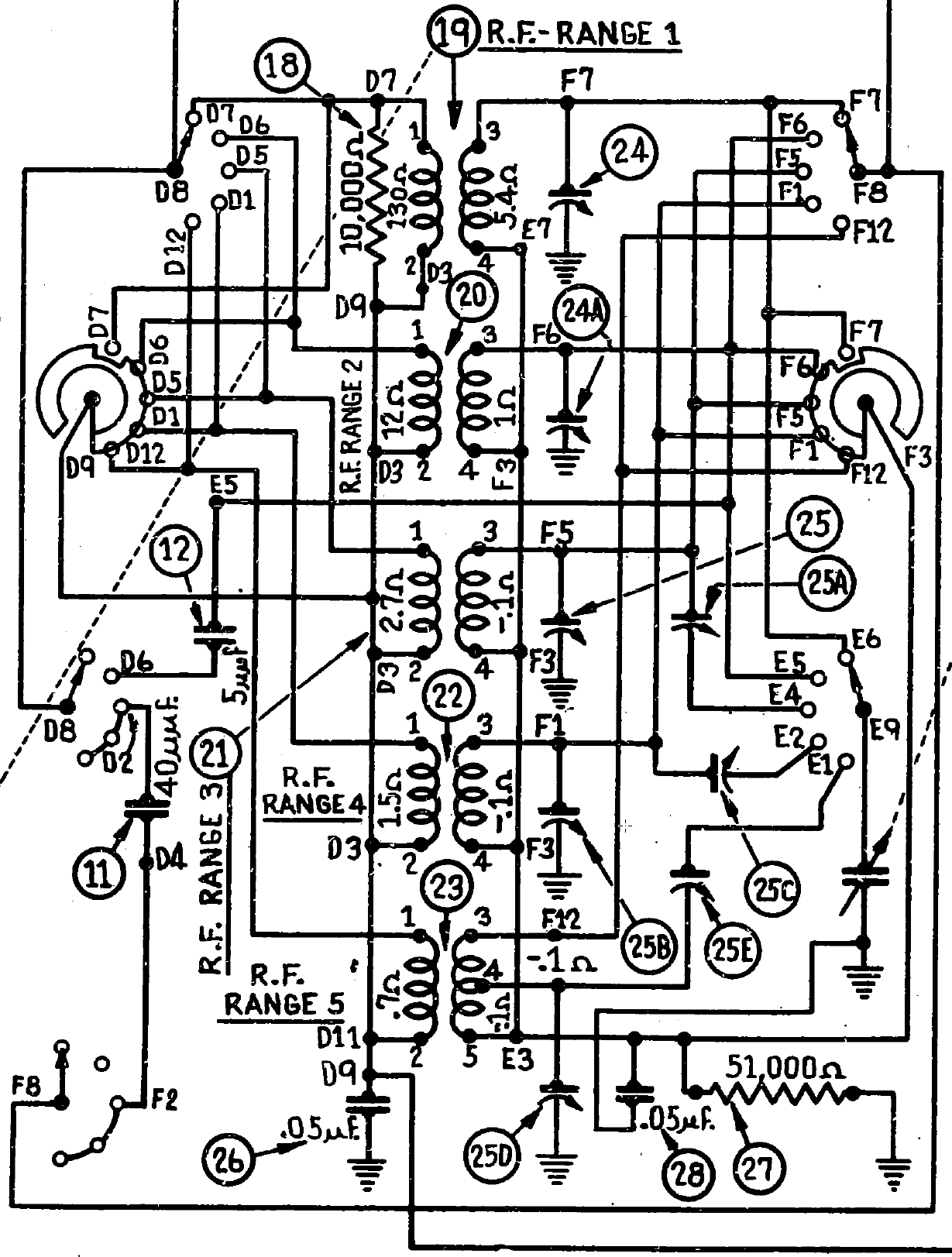
Partial schematic showing the converter subassembly
Partial Schematic – Oscillator Subassembly
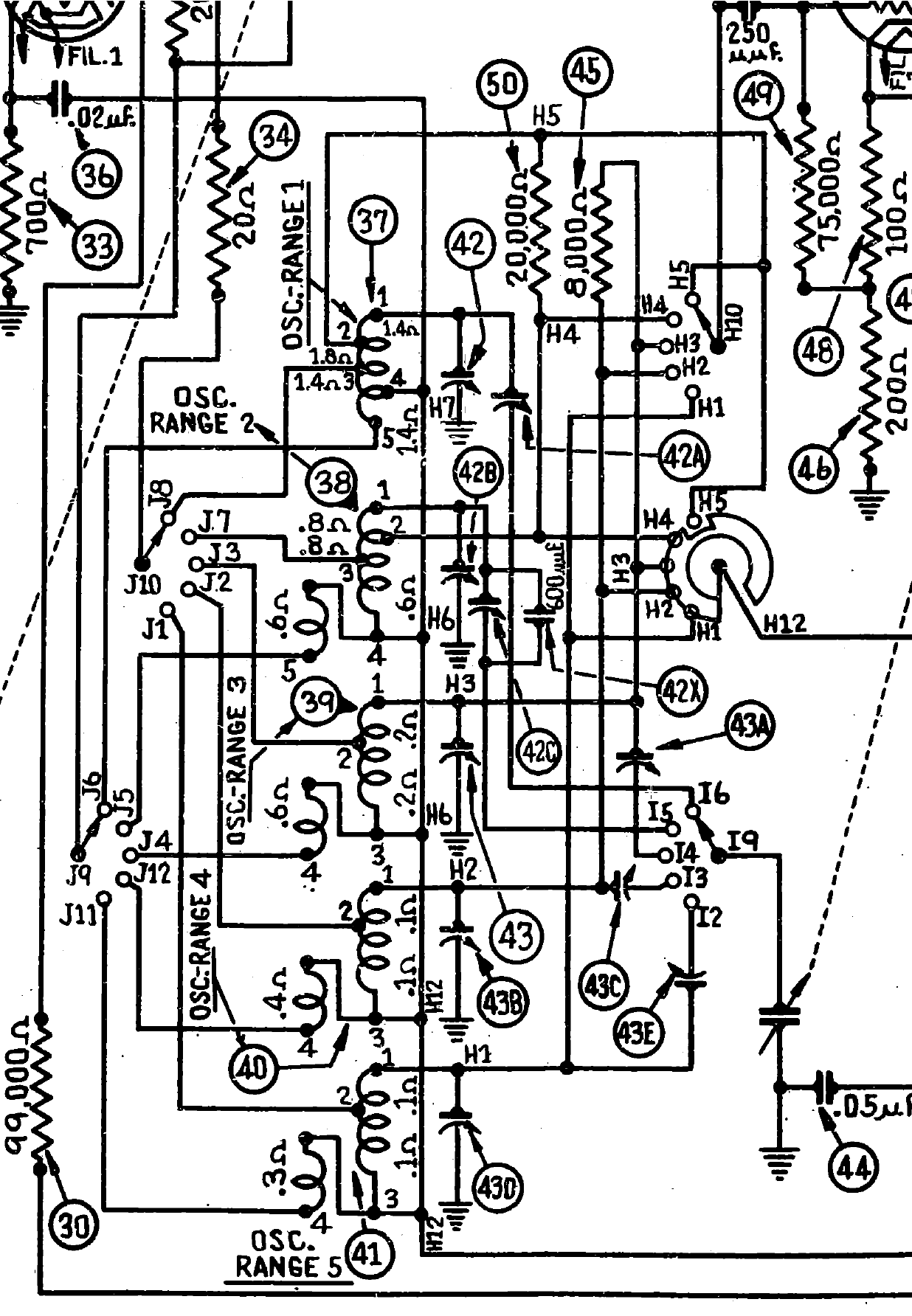
Partial schematic showing the oscillator subassembly
So now that you have seen the resources I am using, let’s get to work.
I carefully inspected each of the three switch wafers. I saw no visible signs of carbon tracks.
A word about carbon tracks. 1937-38 Philco RF units can sometimes develop carbon tracks across a switch wafer. This can occur due to moisture, poor cleaning, dirt, or breakdown of the phenolic due to overvoltage. Arcing from a high voltage point to a ground point can burn a carbon track in the phenolic of the wafer. The carbon track is conductive and effectively causes a short between a B+ source and ground. It manifests itself as a black mark in the phenolic. In extreme cases, it can be a black groove in the phenolic. Sometimes these carbon tracks can be scraped out and fixed, sometimes not.
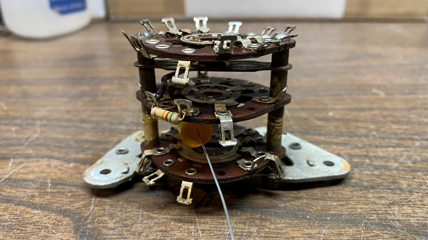
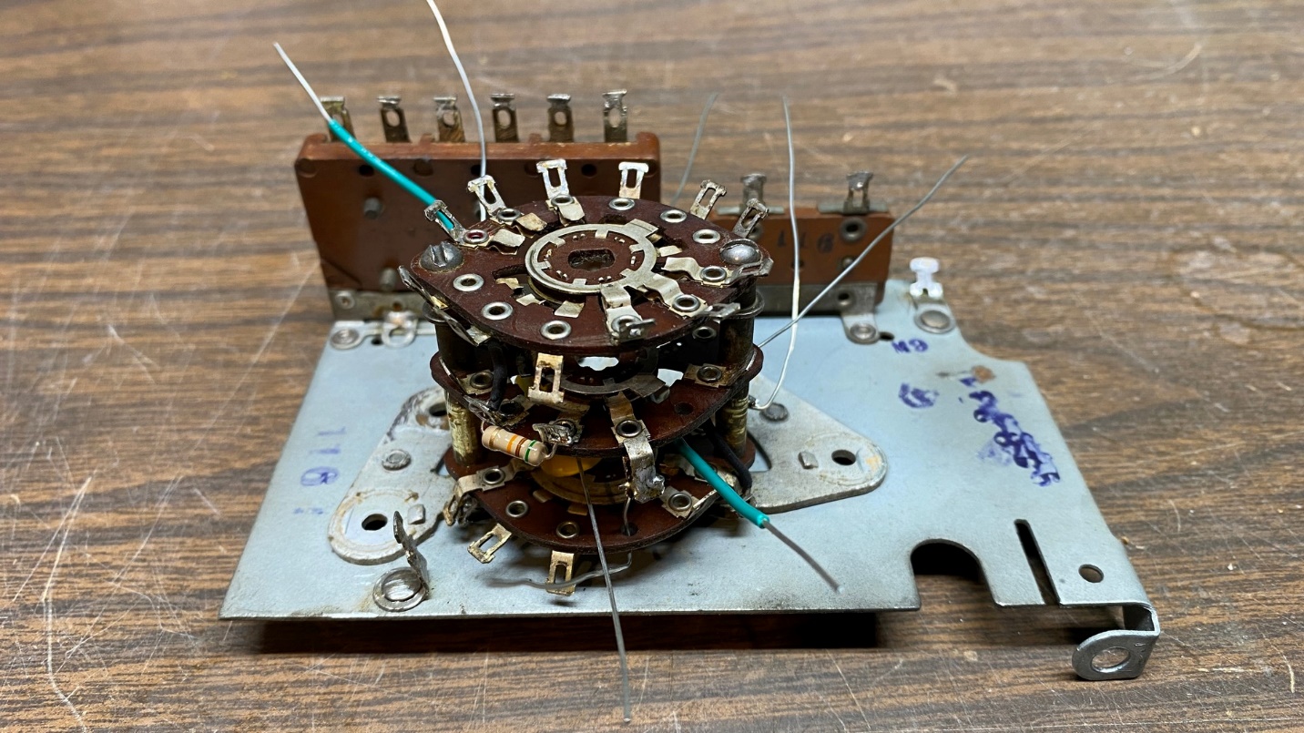
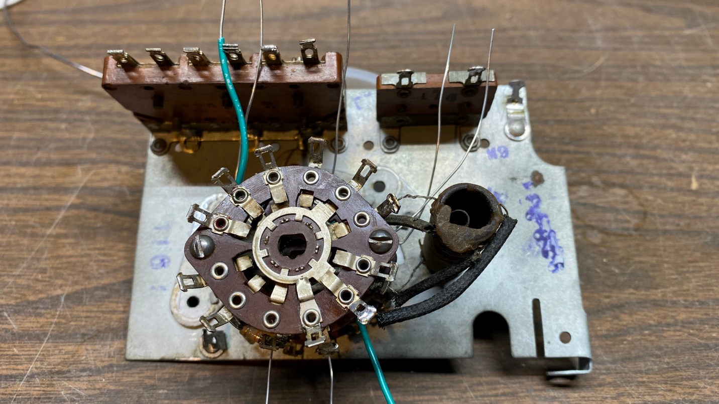
Reassembled switch assembly with a new resistor and new capacitor
Since the switch wafers all looked good, I proceeded with the cleaning. I poured a small amount of 91% isopropyl alcohol into a small container and dipped a toothbrush into the alcohol to then clean the wafers and contacts. The wafers were quite dirty as the alcohol had turned light brown by the time I was finished with all three wafers.
When the wafers dried, I noticed a light-colored film on each. Going over the wafers with the now-dry toothbrush took care of the film and the wafers now looked clean.
After cleaning the wafers, I reassembled the switch assembly. During reassembly, I replaced resistor (8) and capacitor (9).
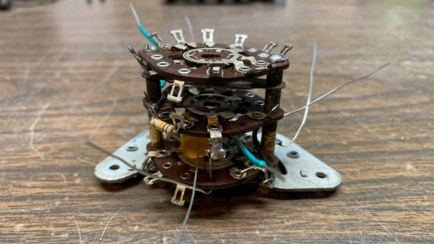
Switch assembly with new wires attached
Once all the wafers, sleeves, etc. were reassembled, I attached the switch assembly to the half-round plate using the same nuts and lockwashers that I had previously removed. I then proceeded to attach new wires as needed.
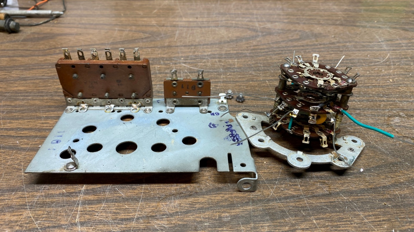
The switch assembly with the bare antenna subassembly
The switch assembly back in place temporarily. It will have to be removed again for installation of the coils.
Another view of the switch assembly back in place temporarily.
Before the switch assembly can be reattached to the plate which also holds the trimmers, I will have to reattach the antenna coils, one at a time.
I quietly debated with myself as to whether I should bake the coils or not. I decided not to and went ahead and reattached the AM antenna coil. The next day, I decided that I probably should bake the remaining four coils, and did so for 30 minutes in an old toaster oven I keep just for the purpose of baking coils and melting wax to remove the “stuffing” from old paper capacitors.
I bake coils at 200 degrees F. This is hot enough to melt the wax and drive out any residual moisture. Baking at a hotter temperature risks damaging the lacquer coating on the wires that were used to wind the coils.
Before I reattached the AM antenna coil, I checked its continuity once again. It tested OK. I then mounted the coil back onto the half-round plate and attached the five wires where they needed to go, using the keys posted above.
Here are how things look with the AM antenna coil back in place and reconnected.
Okay! One coil done, four to go.
I then began to reattach the remaining coils, one at a time. All went well until I got to the antenna coil for band #4. I accidentally tightened its mounting bolt a bit much and broke a piece from the bottom of that coil! So, I stopped everything, removed the band #4 coil, and glued the small piece back in place with clear epoxy. Since it must dry overnight, I could do no more work on this project that day.
The next morning, I returned to the bench to find the epoxy was dry and the coil was ready to be reattached (again). This time I was very careful with tightening it and all went well.
This actually didn’t turn out as bad as I feared. When you set out to do something you have not done before, though, it usually fills a person with a sense of dread and, yes, fear. But I have overcome this and am ready to proceed with the converter or RF section and then, the really hard one – the oscillator section.
To be continued…