Let’s do something about those audio transformers.
It is now time to turn our attention to the two audio interstage transformers in the model 87. Below is a partial schematic showing the original audio circuitry of the 87.
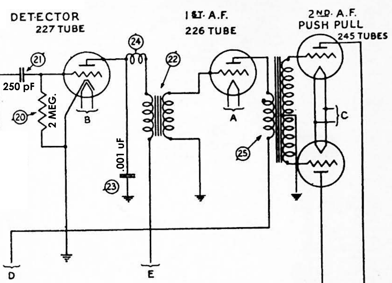
Original model 87 audio circuit.
I propose to make the following changes to the audio circuit:
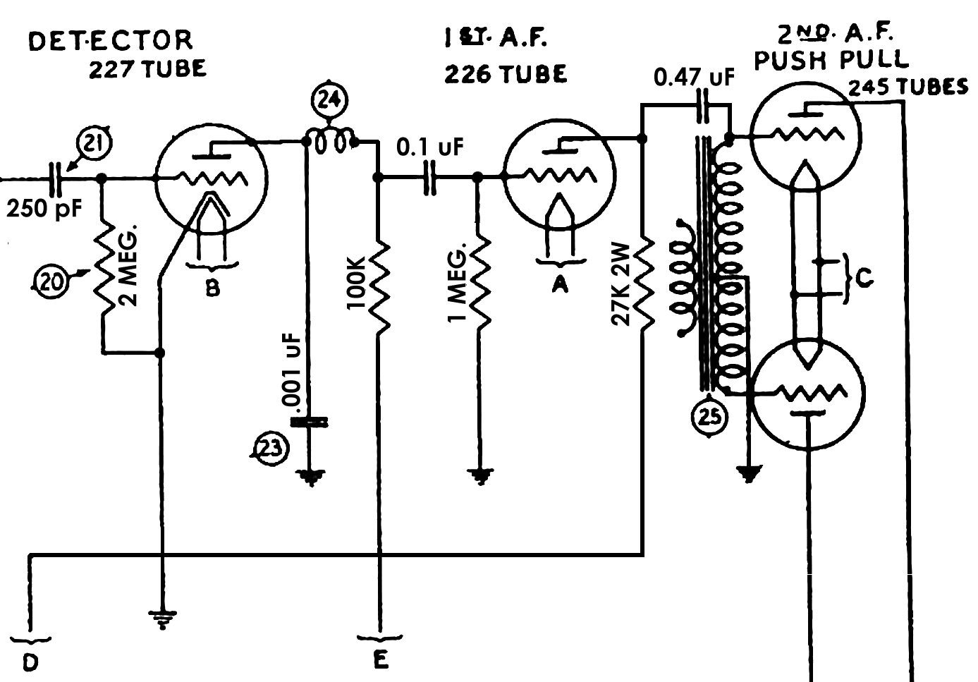
Modified model 87 schematic showing changes to the audio circuit.
I had mentioned previously that the first audio interstage transformer had an open primary. That statement was in error; it was actually the first audio interstage transformer secondary which was open. It is normal for primaries to go open in audio interstage transformers since the primary carries the B+ voltage to the plate of the tube preceding the transformer; it is highly unusual for the secondary to go bad. In any event, I am going to convert the first audio transformer to a resistance-coupled circuit using a 100K resistor, a 1 megohm resistor, and a 0.1 uF coupling capacitor.
The second audio interstage transformer had an open primary. However, the secondary may still be used since it is still good; a 0.47 uF capacitor will serve to transfer the audio signal from the plate of the 26 1st A.F. tube to the transformer secondary. In this manner, phase inversion will still take place through the transformer secondary. A 27K, 2 watt resistor will be used to replace the primary of the transformer.
You can read more about such audio transformer circuit modifications here at the Philcoradio.com Library.
So, without further ado, let’s remove the first audio interstage transformer from the 87 chassis.
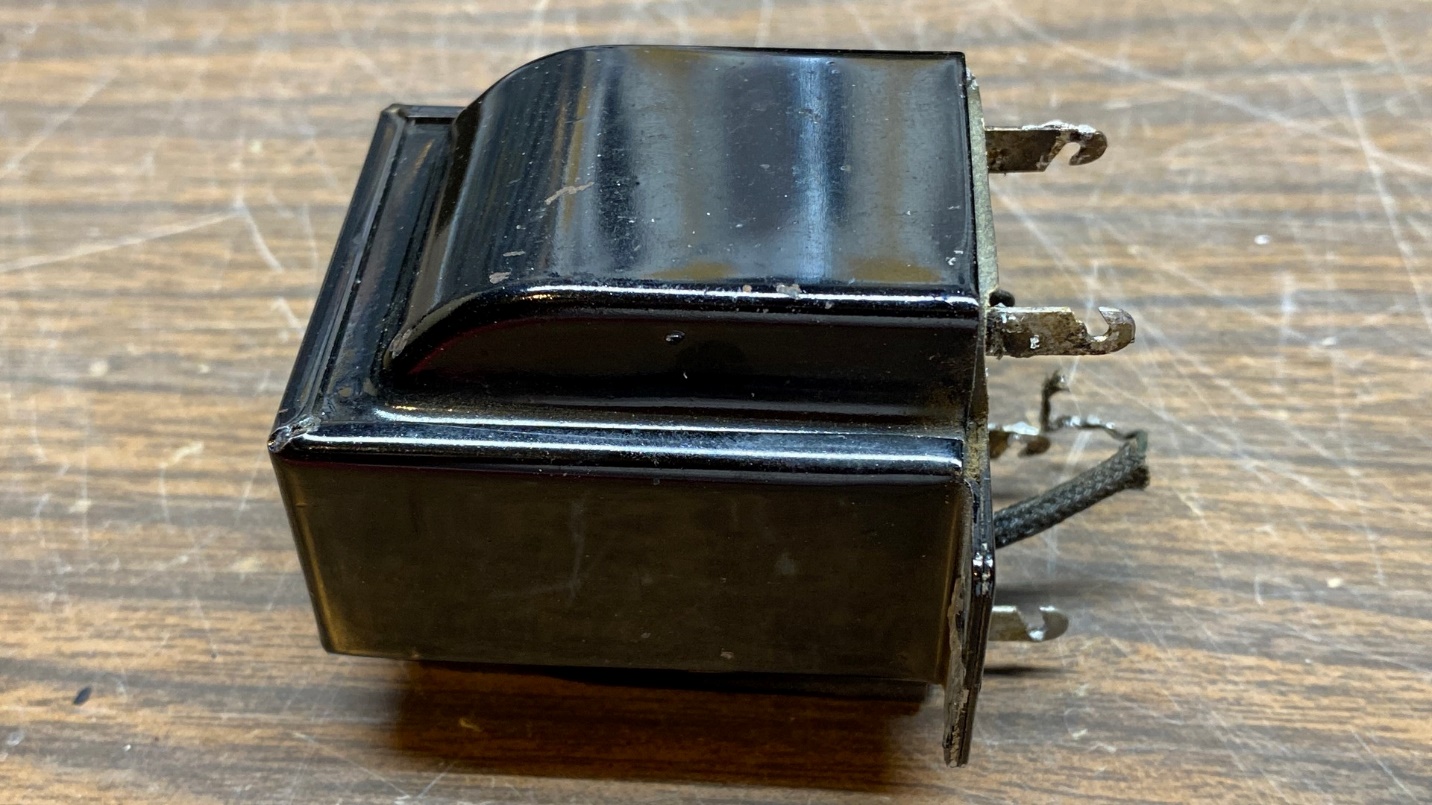
The first audio transformer, part (22).
The bottom plate of the transformer is riveted to the top shell. Using my Ryobi “Dremel” tool, I ground off the rivets on top and was then able to separate the bottom plate (including the terminals) from the rest of the assembly.
Opening the first audio transformer.
Once the transformer was open, it was a simple matter of grabbing the transformer proper with a pair of pliers and pulling it from the outer shell.
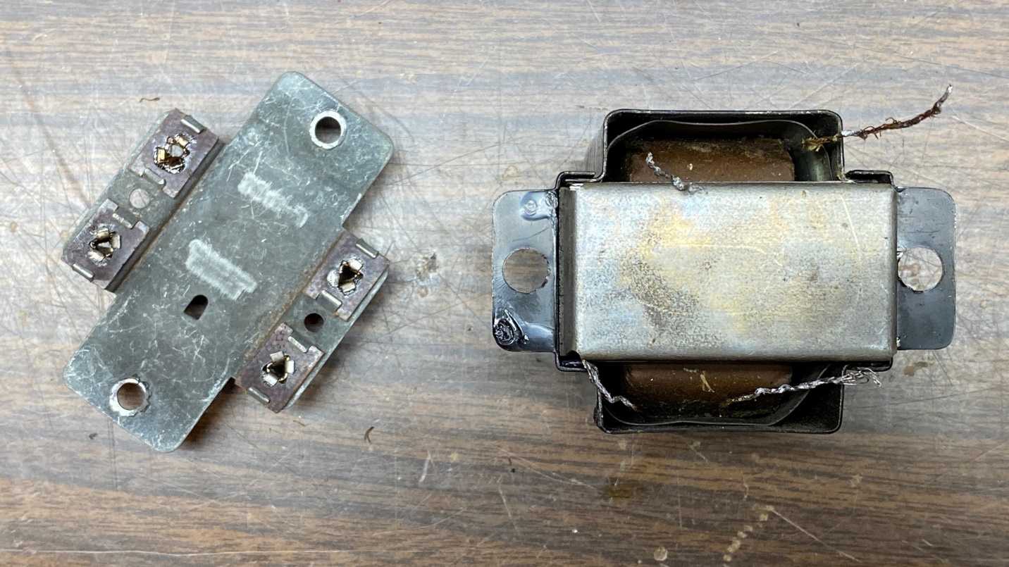
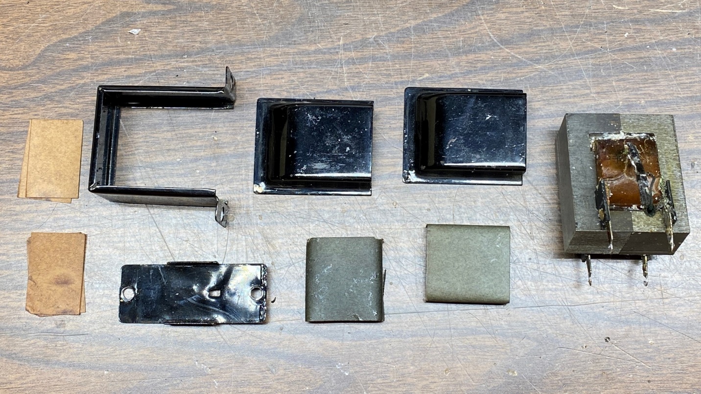
You can see the pieces below.
The disassembled first audio transformer.
Setting the transformer “guts” aside, I connected the resistors and capacitor to the side of the lower plate which will be hidden when everything is reassembled.
I ended up using a 0.15 uF capacitor as I have more of these than I do 0.1 uF caps. Since I use 0.1 uF caps more often in other radios I restore, it made sense to me to use 0.15 uF in this application instead.
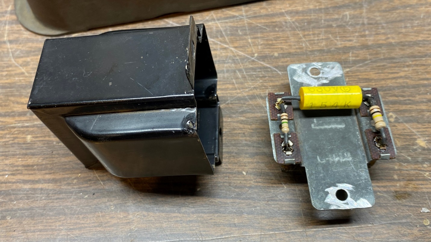
A new resistance-coupled circuit to replace the transformer.
To finish up, I simply set the shell over the bottom plate.
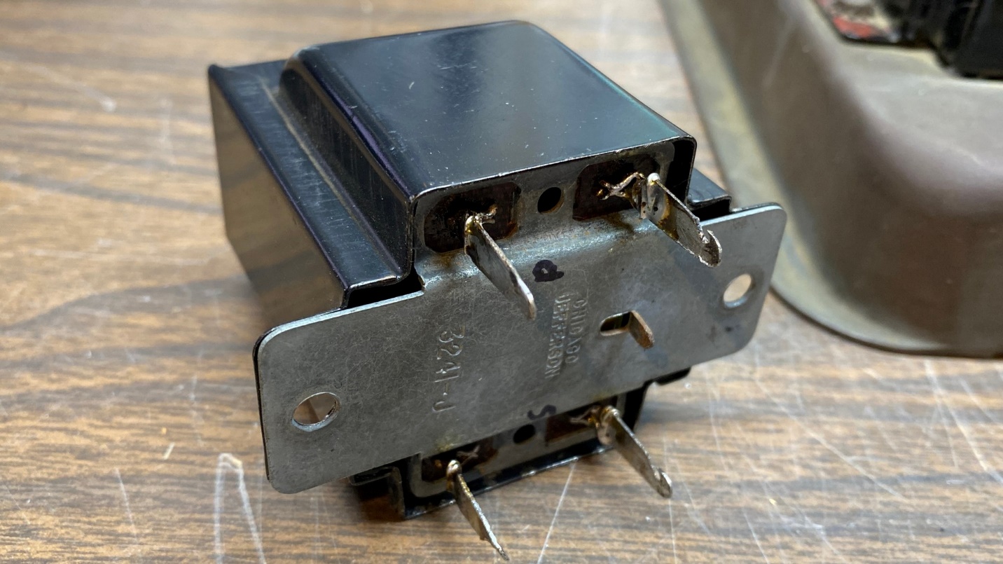
The modified “transformer” looks original and uses the original terminals.
Finally, the modified “transformer” was reattached to the chassis and the wires were reconnected under the chassis. The mounting screws, when tightened, hold the transformer together without the use of rivets.
Yes, I know that some of you are grimacing at seeing this circuit changed to resistance coupling. Yes, I know resistance coupling takes away the step-up action of the original transformer. But resistance coupling is simple – and also offers the advantage of better fidelity. Besides, the way I have done this, I could go back and install one of the new A53-C replacement transformers from Antique Electronic Supply inside the original shell later on if I wanted to do so.
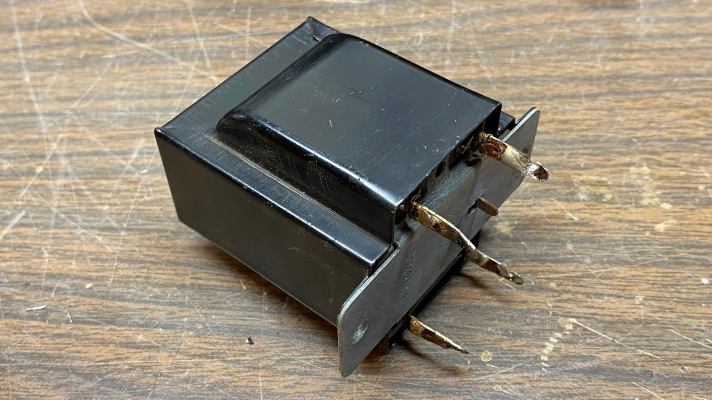
Now it is time to work on the second audio interstage transformer.
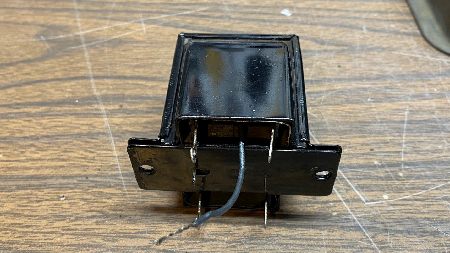
The second audio interstage transformer, removed from the 87 chassis.
Like the first transformer, I had to grind away the rivets which held everything together from the top side of the transformer before it could be disassembled.
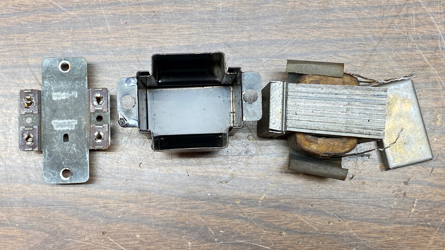
As you can see below, this transformer was made differently from the first audio interstage transformer – and not just because of the tapped secondary.
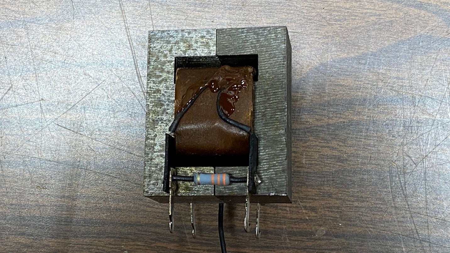
The disassembled second audio interstage transformer.
Once the transformer was disassembled, I unsoldered both primary leads, added heat shrink tubing to completely cover them, then used some hot glue to stick them to the sides of the fish paper. Now the primary will be completely disconnected from the circuit.
Next, I added a resistor to replace the original primary winding. I did not have any 27K, 2 watt resistors, but had several 33K, 2 watt resistors. So, I used a 33K instead.
A resistor is now used in place of the transformer primary.
Now it was time to reassemble the transformer. Here is where I ran into a problem – the transformer “guts” refused to go back into the frame. I finally was forced to remove one of the thin center laminations.
Unlike most transformers which use interleaved “E” and “I” shaped laminations, this one only uses “E” laminations with a tiny gap in the center.
After removing one “E” lamination from each side, the “guts” (unwillingly) went back into the frame.
The transformer was reassembled after modifications were made.
Once everything was back together, this modified transformer was also reattached to the chassis and the wires were reattached under the chassis.
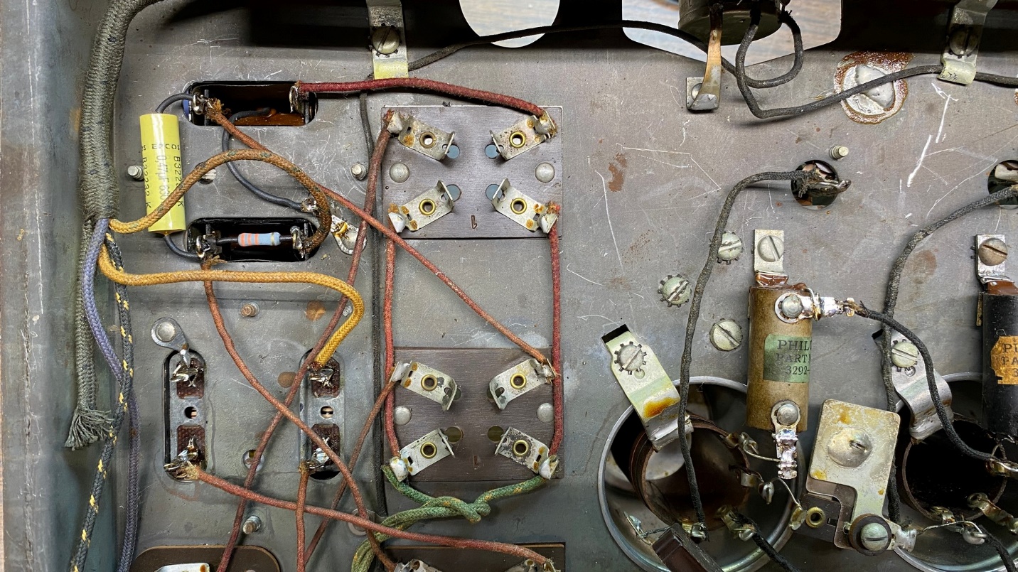
How the modified transformers look under the chassis (left side of picture).
Finally, I added a 0.47 uF, 630V capacitor across “primary” and secondary as shown in the modified partial schematic near the top of this page.
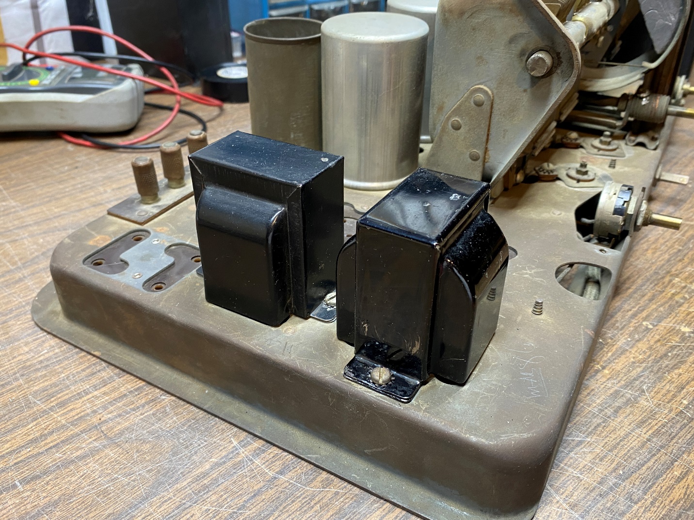
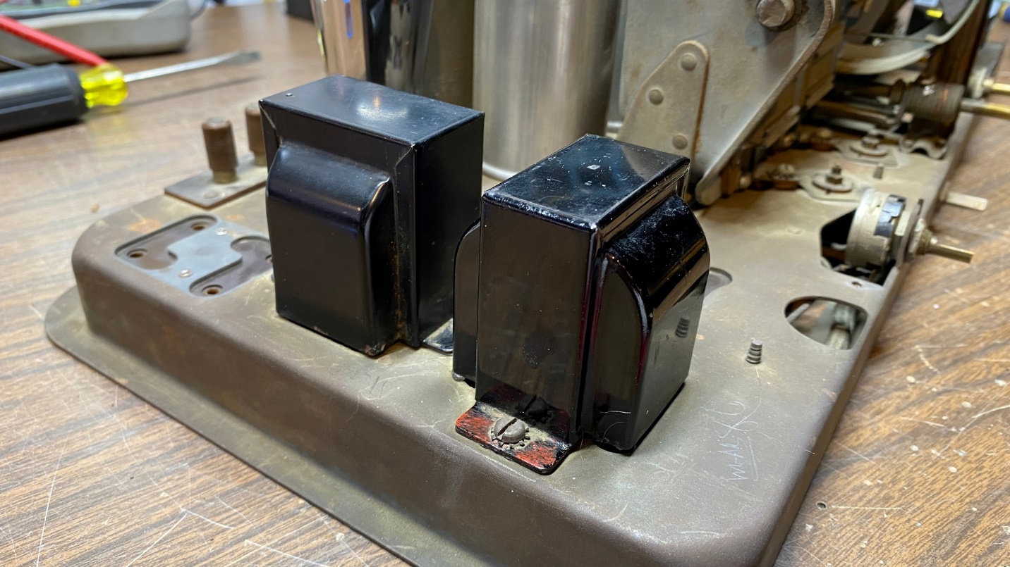
Modified transformers now reattached to the chassis.
This job is finished, and the transformers still retain their original appearance.
And as with the first audio transformer, I am aware that I could use an Antique Electronic Supply A53-C interstage transformer to replace the second audio transformer. Due to the construction of this transformer, however, it would be more of a challenge to mount the new transformer inside the original shell without some serious modifications.
There are still several small items, and one more large item, which need to be addressed. Next time, I will address most of the remaining issues with this chassis.