Many radio collectors – myself included – have always thought of the 1929 Philco model 83 radio as being the same as model 87, only designed to operate on 25 cycle AC current. However, that isn’t quite true.
Yes, model 83 was sold in the same lowboy, highboy, and highboy de luxe cabinets as was model 87. But there are differences between the two chassis which go beyond the choice of 25 cycle or 60 cycle AC current.
The purpose of this post is to discuss those differences, and to present you with useful service information in the event you may need to work on a model 83.
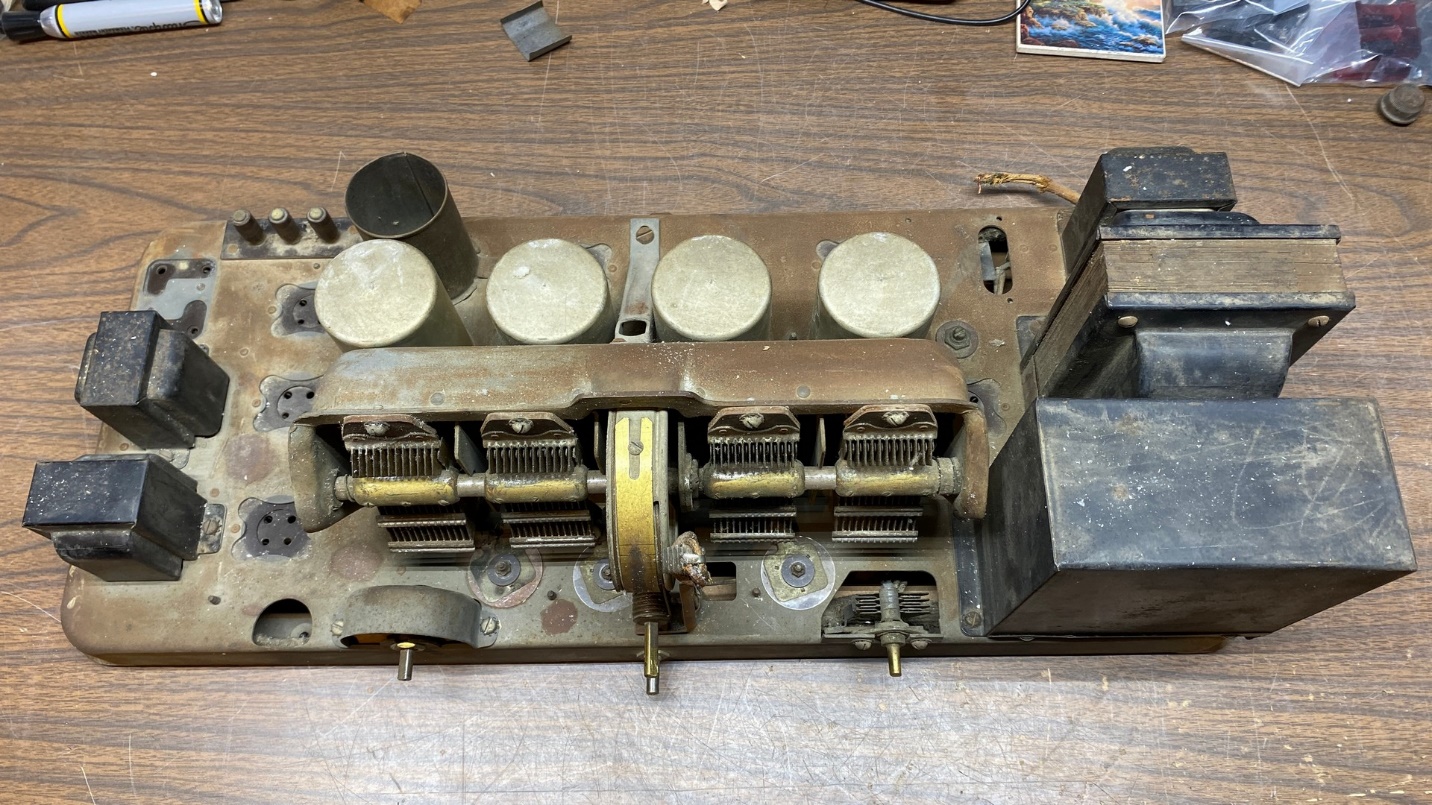
First and foremost, model 83 does not use push-pull type 45 output tubes. Instead, it uses push-pull 71A output tubes, as do Philco models 82 and 86. This also means the model 83’s power transformer is different from the 87 power transformer; it has an extra 5 volt filament winding for the 71A tubes instead of a 2.5 volt winding for 45 tubes. The dial lamp, which is powered by the output tube filament circuit, is 5 volts instead of 2.5 volts. This will actually make it easier to replace the dial lamp – you can use a screw base LED lamp designed for 6.3 volt operation and it should work fine.
Only one filter choke is used in model 83 even though a hole was punched in the chassis for the unused second choke. The large power resistor has four sections instead of three in the 87; the extra section is used instead of a second filter choke.
The filter condenser block has eight terminals underneath, compared to 10 terminals in the model 87 filter condenser block. The model 83 block is part number 3279, the same part number used in model 82 which is the 25 cycle version of model 86. The model 83 block is very large and one of its mounting ears fastens on the side of the chassis as there was no room for it on top of the chassis.
Overall, model 83 has more in common with models 82 and 86 than with model 87. It lacks the headphone jack used in models 82 and 86, and the chassis layout matches the 87.
Let’s compare the two radios. First, a schematic of model 87:
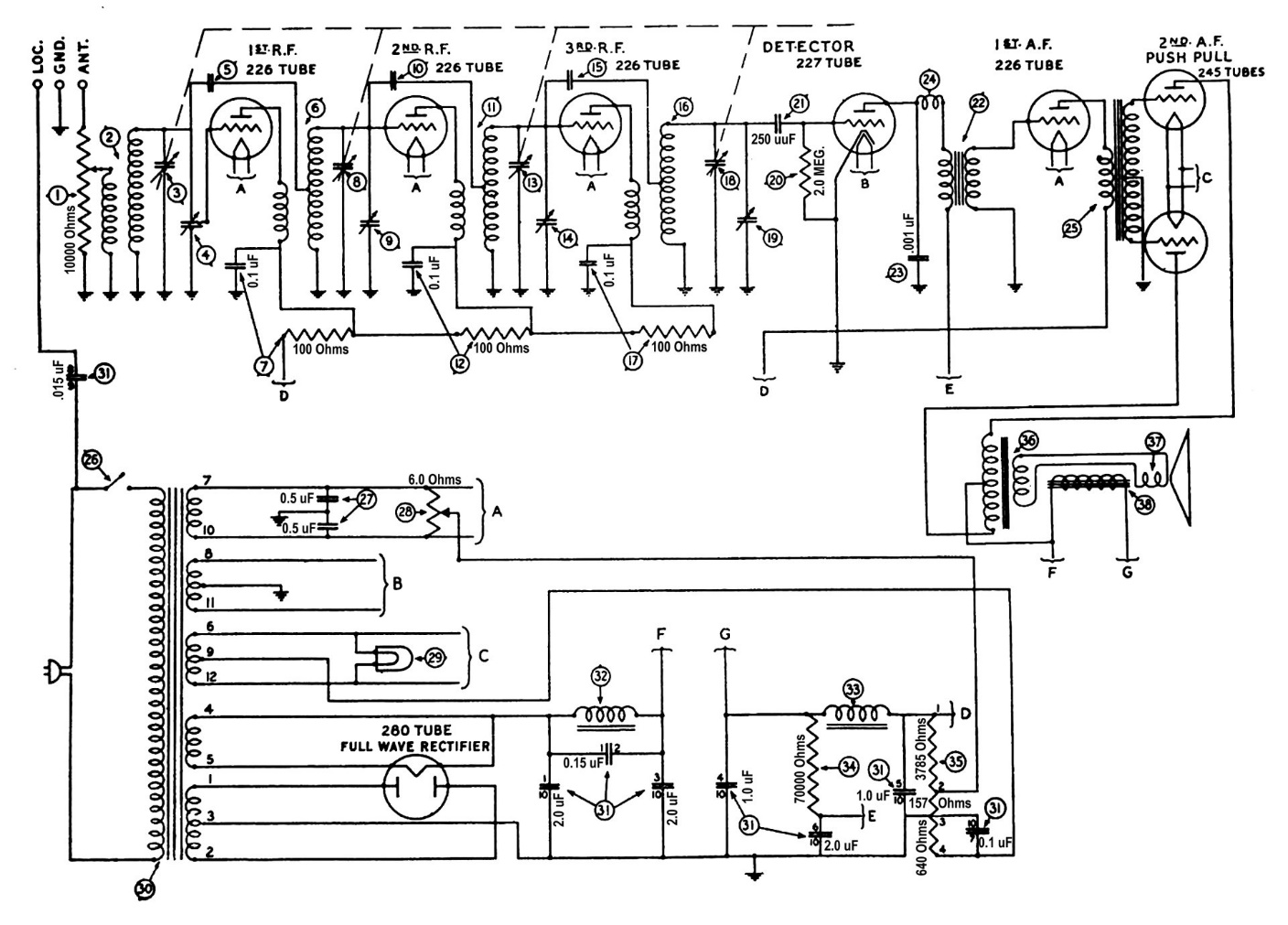
Philco model 87 schematic.
Now, compare the above schematic to the model 83 schematic:
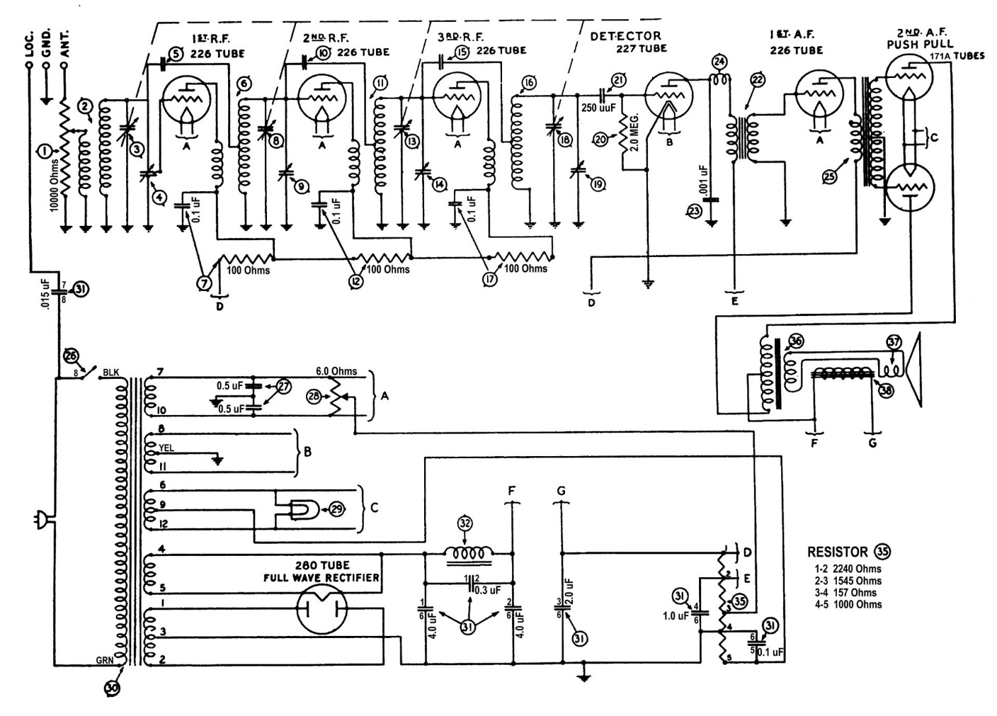
Philco model 83 schematic.
Notice the differences in the power supply of model 83. Second filter choke (33) and 70K, 1 watt resistor (34) are not used. The 2 uF section of the filter condenser block which connects between one end of the 70K resistor and ground is also eliminated. B+ terminal E is moved to terminal 2 of the power resistor. I confirmed by taking measurements on the Philco model 83 parts chassis that, in model 83, B+ terminals D and G are connected together and are the same.
In model 87, there is a 3785 ohm section of the power resistor which connects between B+ terminal D and the wiper arm of hum control rheostat (28). In model 83, the 3785 ohm section is split into two sections: a 2240 ohm section between B+ terminals D and E, and a 1545 ohm section between B+ terminal E and the wiper arm of rheostat (28). The resistance between terminals 4 and 5 of the large resistor is 1000 ohms in model 83; there is a 640 ohm resistance between terminals 3 and 4 of the large resistor in model 87. The resistance is increased to 1000 ohms in model 83 to properly bias the 71A tubes.
Let’s look at the model 83 filter condenser block, part number 3279:
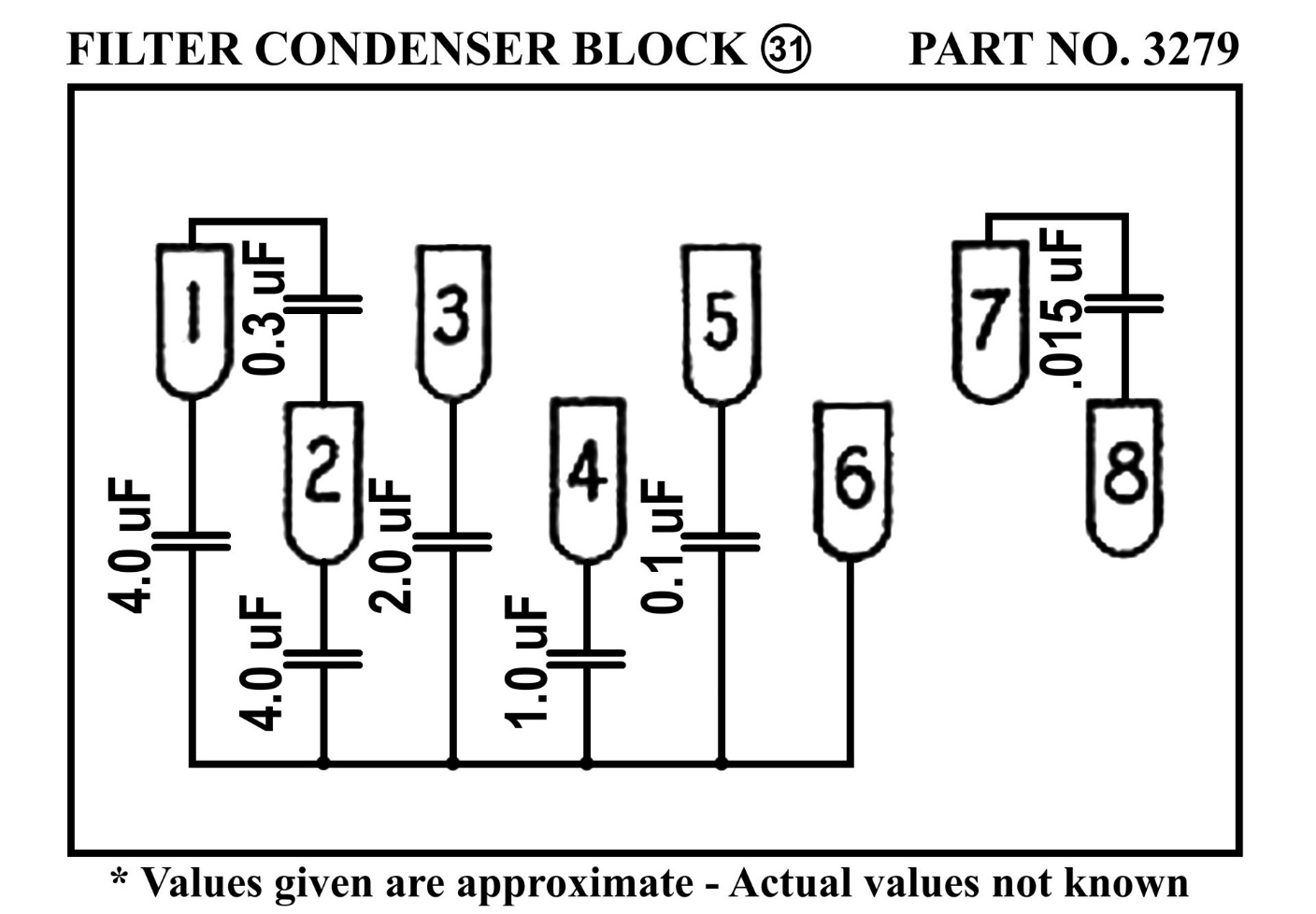
Philco model 83 filter condenser block. This is the same part used in model 82.
Since I have not been able to find anything documenting the actual capacitor values used in the model 83 filter condenser block, I frankly guessed at the values. The values I suggest above should be sufficient to properly operate the radio. Actually, since 25 cycle AC is no longer used as we have been on a 60 cycle (60 Hz) standard for many decades, it would be fine to use 2 uF in place of the 4 uF capacitors; 0.15 uF in place of the 0.3 uF capacitor; and 1 uF in place of the 2 uF capacitor. However, the larger values may be used with no trouble.
From a safety point of view, it would be desirable to eliminate the .015 uF capacitor between terminals 7 and 8. This, of course, will render the radio’s LOC terminal ineffective. It will also make your radio safer to operate as it is never a good idea to try and use one side of the AC line as an antenna!
It is my hope that the above information will prove helpful, especially since Philco apparently did not properly document their model 83 radio.