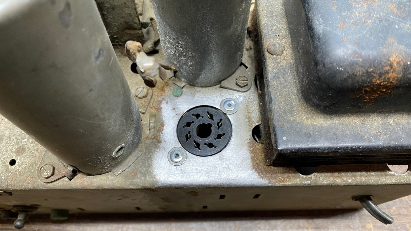
Last time, I was admiring how clean the chassis was around the newly replaced IF tube socket and wishing the rest of the chassis looked like that on top.
After thinking about it for a while, I decided to do something about it.
I knew that merely cleaning the chassis with Go-Jo or Goop would not suffice. I’ve tried those products before. They barely remove any dirt, leaving the chassis looking almost as bad as it did before I made the cleaning attempt.
I should also mention that by now I had found, and purchased, an RCA T8-14 chassis in order to obtain a better tuning condenser for this chassis. Therefore, I knew I would be removing the original, damaged tuning condenser.
So, I made the decision to remove as many topside components as possible in order to make the top of the chassis sparkling clean with the aid of a Dremel abrasive buff.
Fortunately, RCA provided extensive service data for the radios they manufactured during this time, even including point-to-point wiring diagrams of all components on the underside of the chassis. This would allow the removal of components without the necessity of trying to remember what connected where.
All tubes were removed from their sockets, then both IF transformers were removed.
I removed all the tubes. I then turned the chassis upside down and unsoldered all wires and components from both IF transformers. Turning the chassis right side up again, I then unbolted and removed the IF transformers.
I then began preparations for removal of the tuning condenser. There is a linkage which connects the band switch shaft to a pointer at the bottom of the dial scale. This pointer shows the radio operator which band to which the radio is set.
At first I thought I could loosen the setscrew on the band switch and then pull this piece off the shaft once the tuning condenser was free. I soon realized that this would not work.
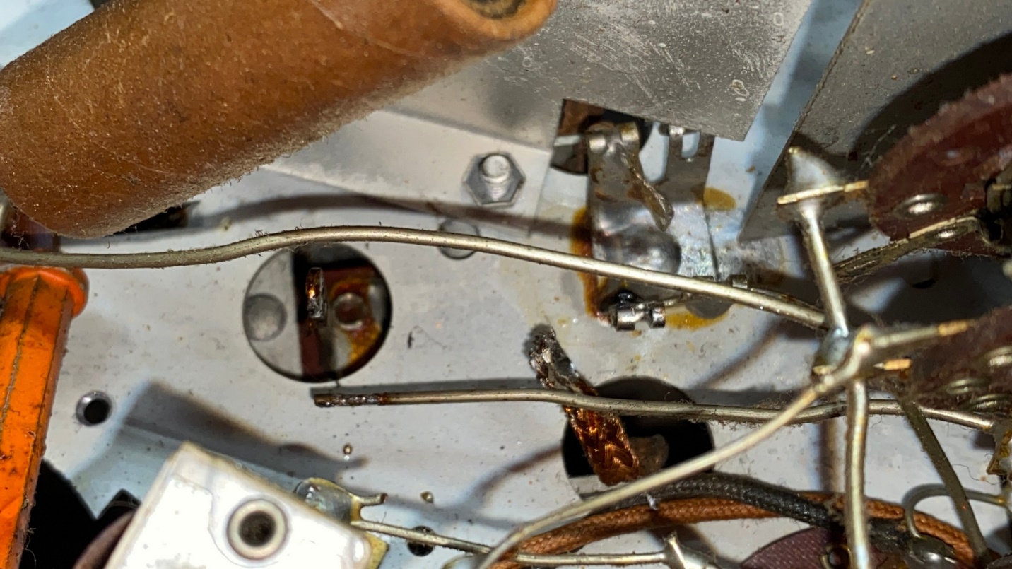
The simplest way to remove the linkage is simply to remove the bolt with the large hex head from the linkage. This bolt is held in place by a small nut and lockwasher in back. If the small nut is held in place with large needle nose pliers, a socket wrench of the appropriate size may be used to loosen the bolt.
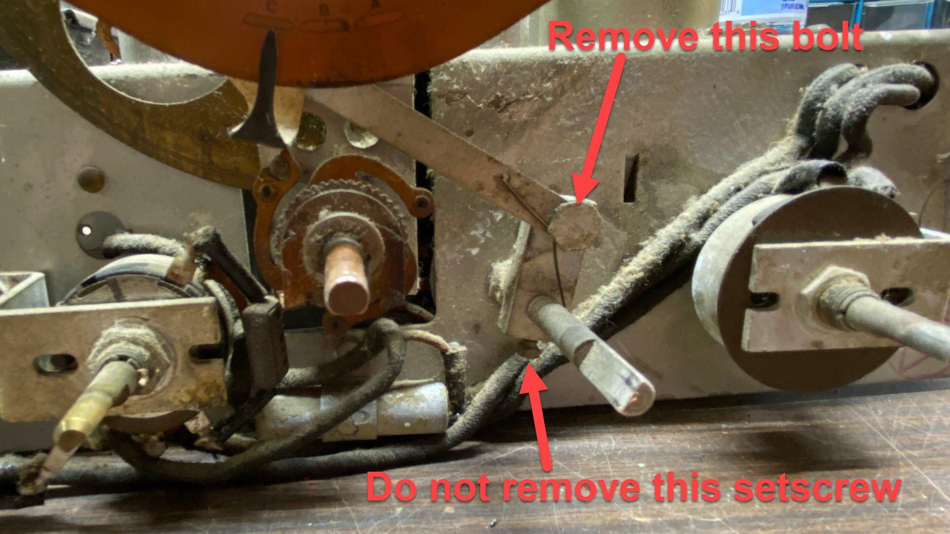
The linkage between the band switch and the band indicator at the bottom of the dial must be removed.
I noticed four copper braids which connected the tuning condenser frame to four points on top of the chassis. These four points were unsoldered, and the braids removed.
Next, I turned the chassis upside down again.
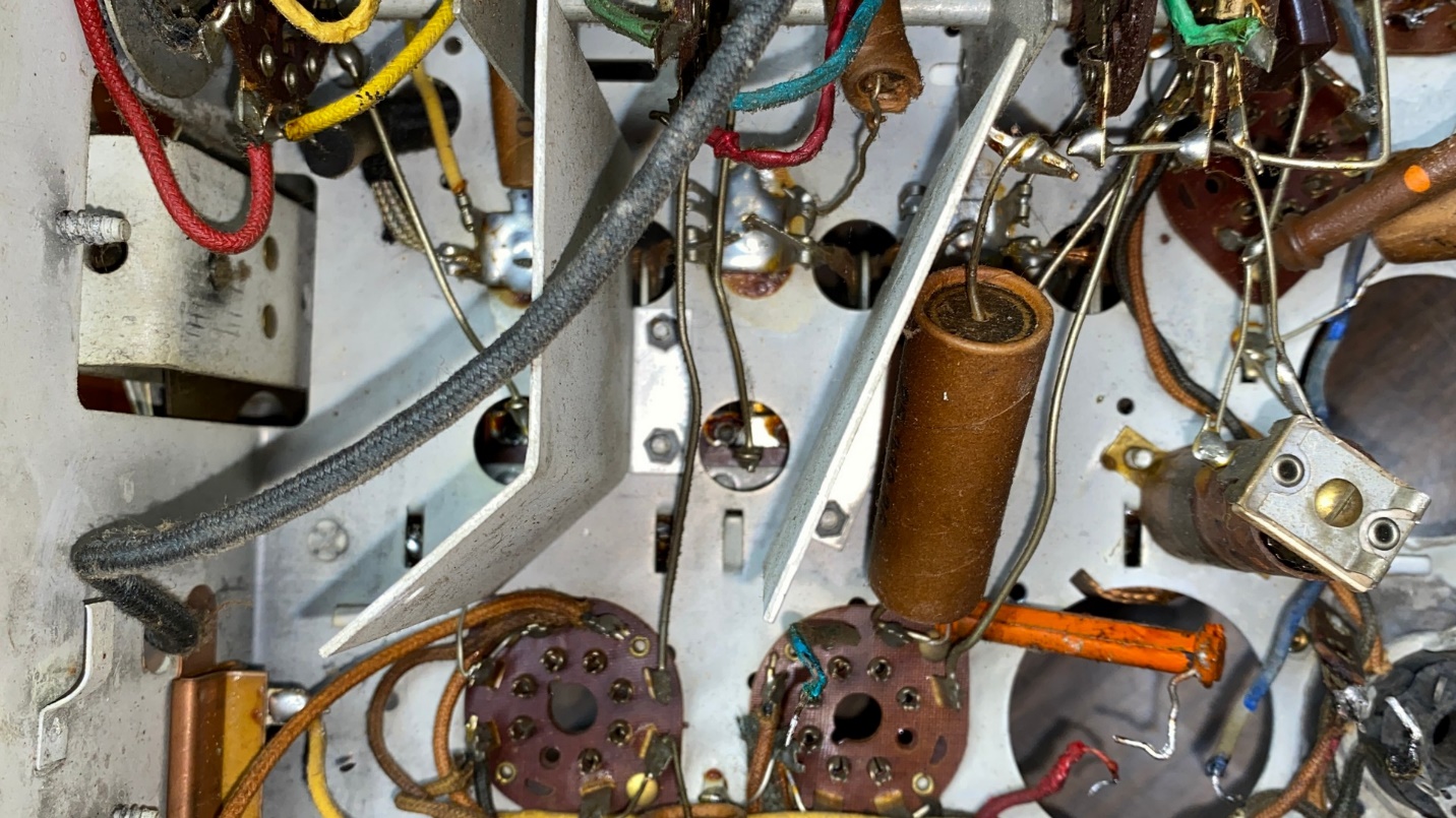
Three stator terminals and four more copper braids must also be unsoldered from underneath to remove the tuning condenser.
I knew I would have to unsolder three wires, one from each of the three stator terminals of the tuning condenser. What I did not realize was that there were four more copper braids soldered to the chassis underneath, which also had to be unsoldered and removed.
The rearmost tuning condenser stator terminal and copper braid are now unsoldered.
Once the stator terminals and the additional copper braids were unsoldered and wires/braids removed, it was time to flip the chassis upright once again.
Removing three mounting nuts, lockwashers, and flatwashers in order to remove the tuning condenser.
Now, it was a simple matter of loosening and removing the three nuts, lockwashers, and flatwashers which mount the tuning condenser to the chassis.
With these removed, the tuning condenser, dial assembly, and tuning shaft could now be pulled up and away from the chassis as an assembly.
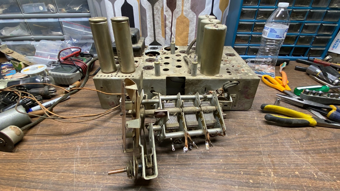
The tuning condenser is now removed from the chassis.
Now, I had to flip the chassis over yet again to remove the mounting nuts for the two electrolytic capacitor cans. Both mounting nuts were stuck and would not loosen until I tapped on each one with a small hammer and long-handled screwdriver placed in such a manner that each nut would be forced to loosen.
Eventually, these components were also removed from the chassis.
As I intend to restuff the electrolytic cans with new components, these needed to be removed anyway.
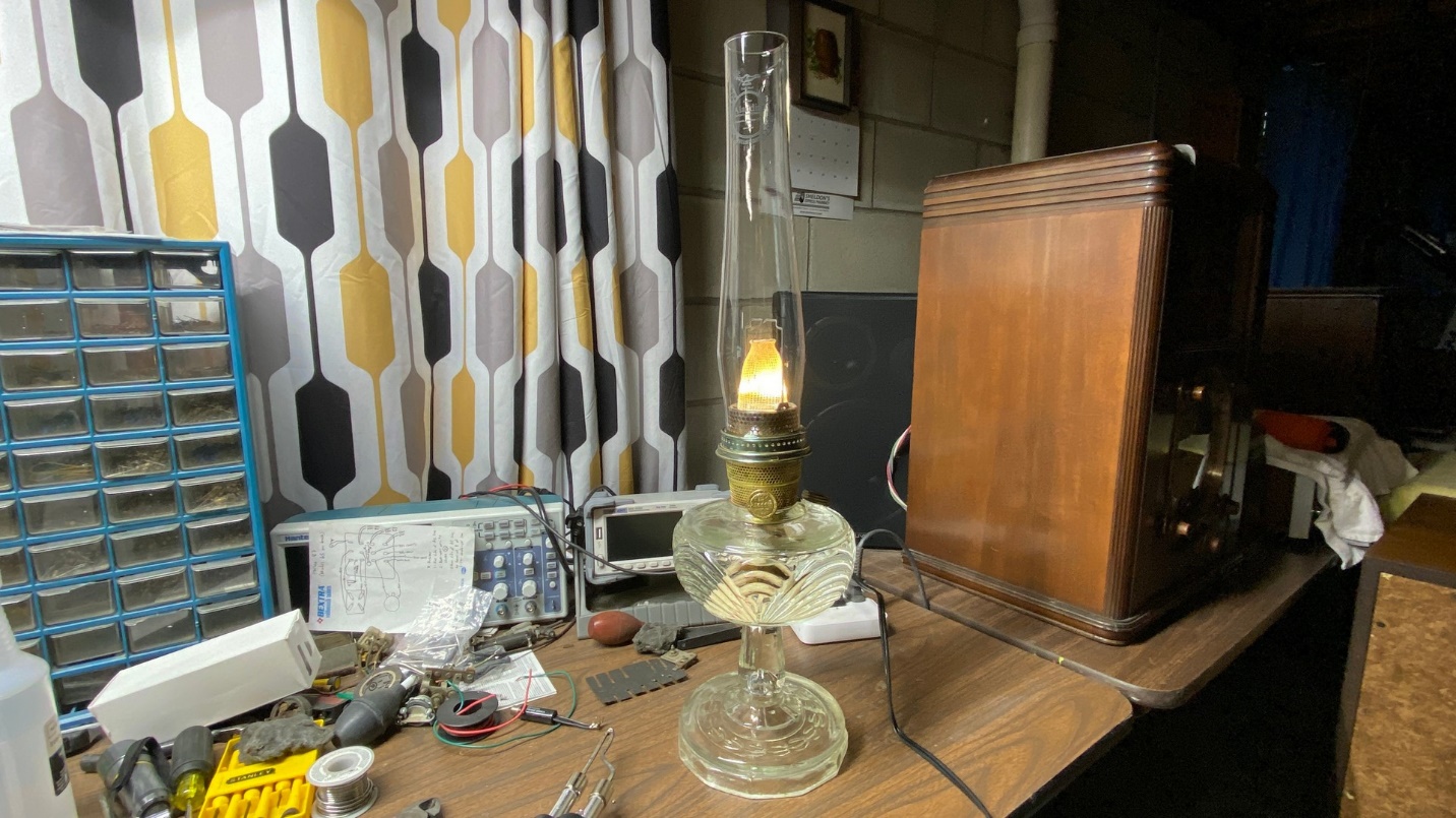
An Aladdin clear Washington Drape (B-53) lamp provides supplemental heat to my work area during these cold winter days at the workbench.
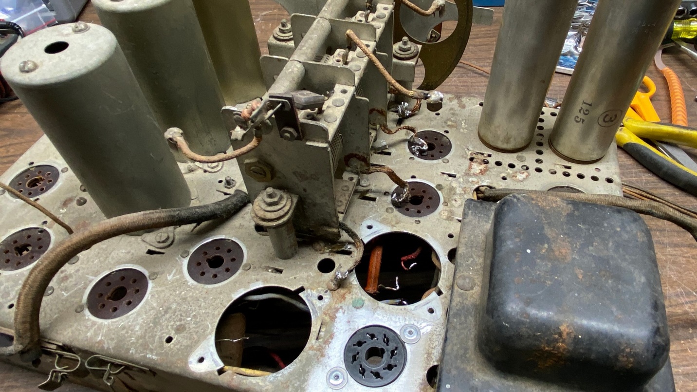
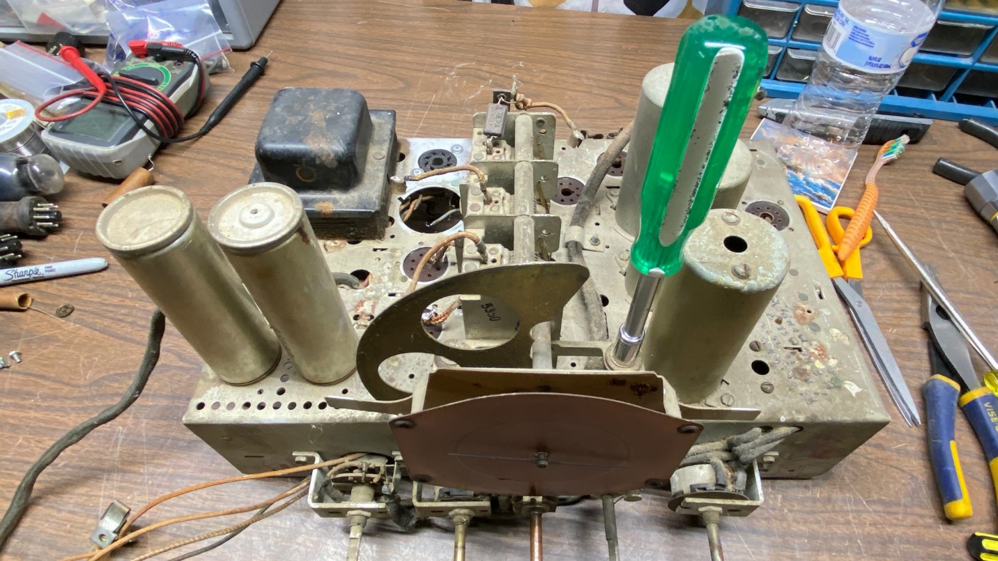
At this point, the only remaining topside components on the chassis were the three RF coils and the power transformer.
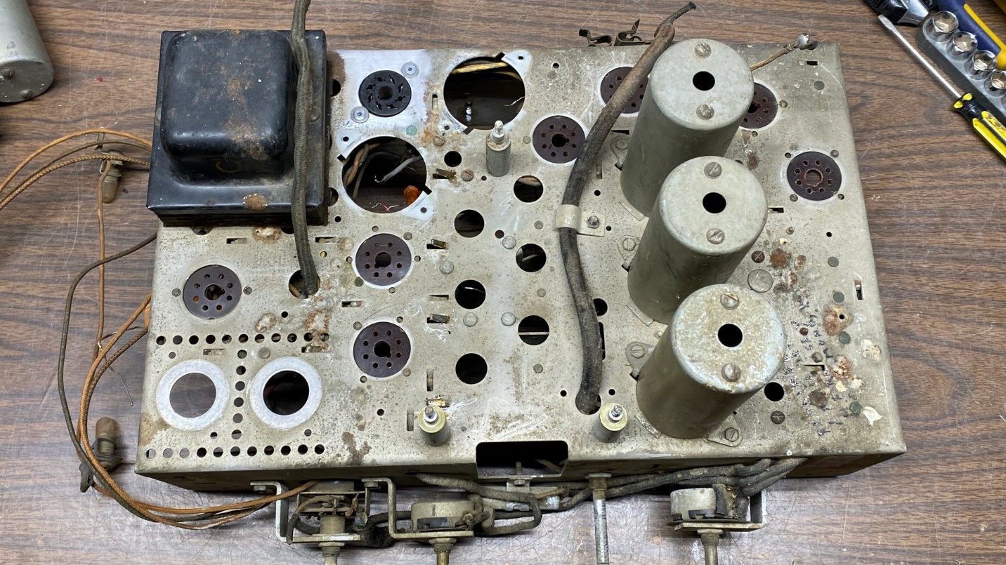
At this point nearly everything has been removed from the top of the chassis.
We’re out of room again, so this is a good point to take another break. I need to think about what I want to do about those RF coils – whether to remove them, or to merely remove the shields and then protect the coils by taping paper around them. The power transformer is permanently mounted to the chassis with metal tabs and would not be possible to remove without damage.
Next time, I will decide just how to proceed in preparing this chassis for a thorough cleaning.