In this installment, I am going to open the large multi-section filter condenser can, disconnect the old wires from the terminal board, and install new components.
Let us take a look at the can.
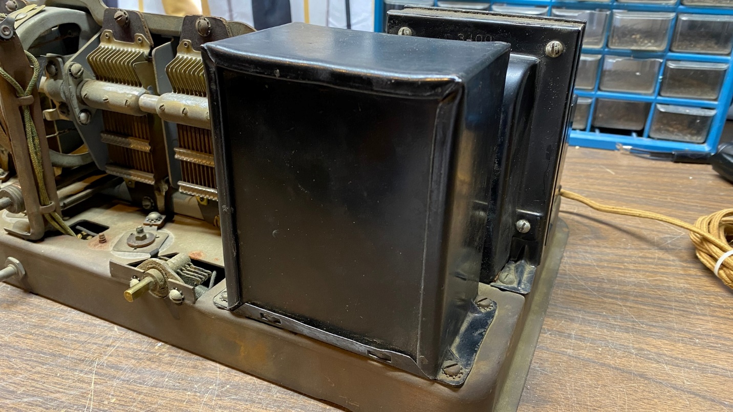
The Model 87 filter condenser can in foreground, in front of the power transformer and to the right of the tuning condenser.
This is it – a large rectangular metal can, mounted just in front of the radio’s power transformer. This can holds eight paper capacitors, and the entire unit is encased in tar inside the metal can.
In case you are wondering, What were they thinking?, sealing various radio components in tar was commonplace in the late 1920s among several radio manufacturers. Atwater Kent, as one example, sealed entire power supplies, including the power transformer, in one large metal can in sets such as models 40 and 44.
By looking through old Philco parts catalogs, it is apparent that Philco supported model 87 with replacement parts, including the big metal filter condenser can, up to World War II. After the war, it appears the filter can was no longer available, along with other major parts such as transformers.
But enough model 87 sets have survived that it is apparent that these likely kept playing for many years after World War II before being retired to attics, barns, and basements.
But I digress.
There are two ways to go about removing the can from the chassis. You could unsolder every lead under the chassis, remove the entire can assembly, then open it up. Or you could remove the mounting screws, open up the can, cut the wires and then proceed with installation of new capacitors.
I chose the latter.
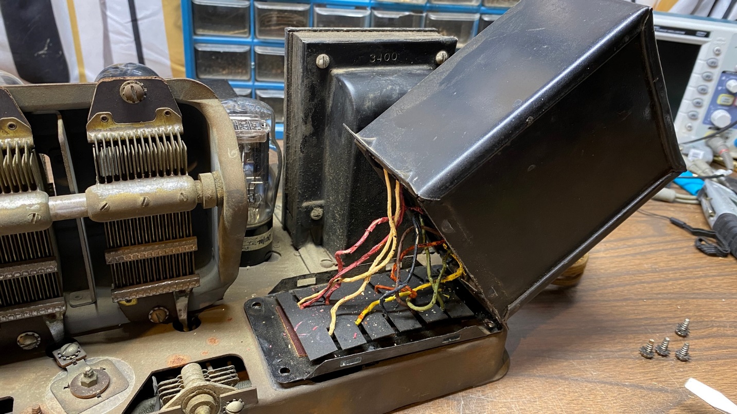
Removing the top portion of the filter condenser can.
The base of the can may be pulled free of the rest of the can once the four mounting screws are removed, and the base is pried free from the main part of the can as shown above. In this manner, the wiring under the chassis need not be touched. This will make the job slightly easier.
I pulled the can up enough to access the wires, cut the wires, and set the main part of the can aside.
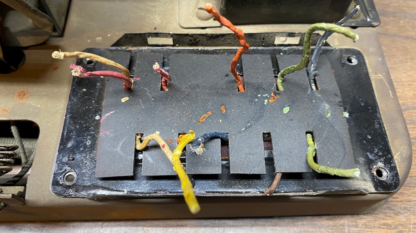
What is left at the base of the filter condenser can after the top portion has been removed.
Here is what remains. Notice the fiber divider, through which each wire passes. Remove this divider.
Now, you can see where each individual wire connects on top of the can base. It is now a simple matter of unsoldering and removing each of these wires.
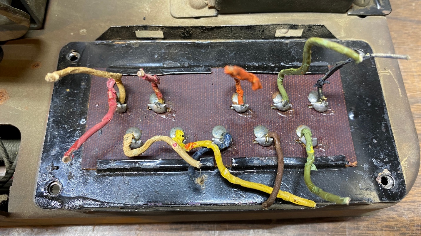
These wires will have to be unsoldered and removed.
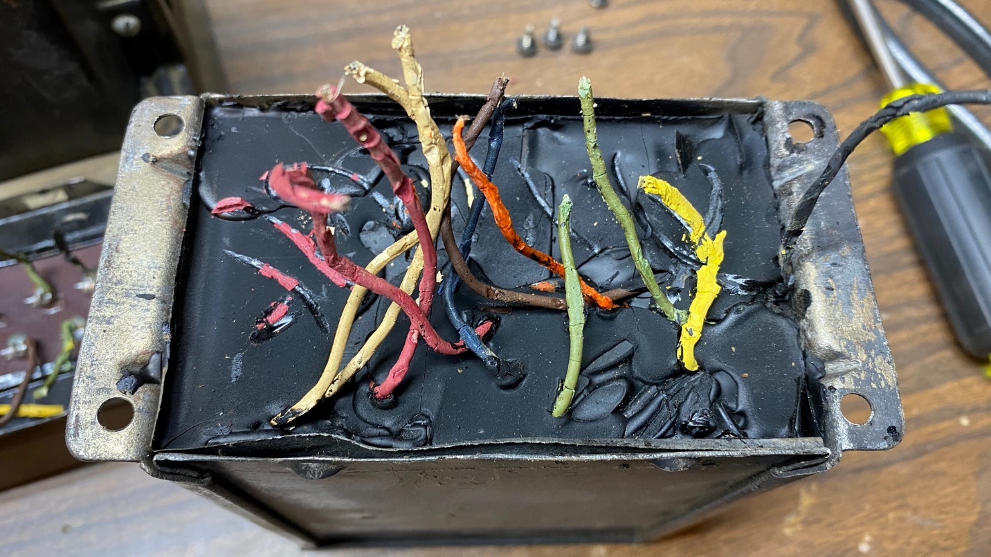
Once the wires are unsoldered and removed, things look like this.
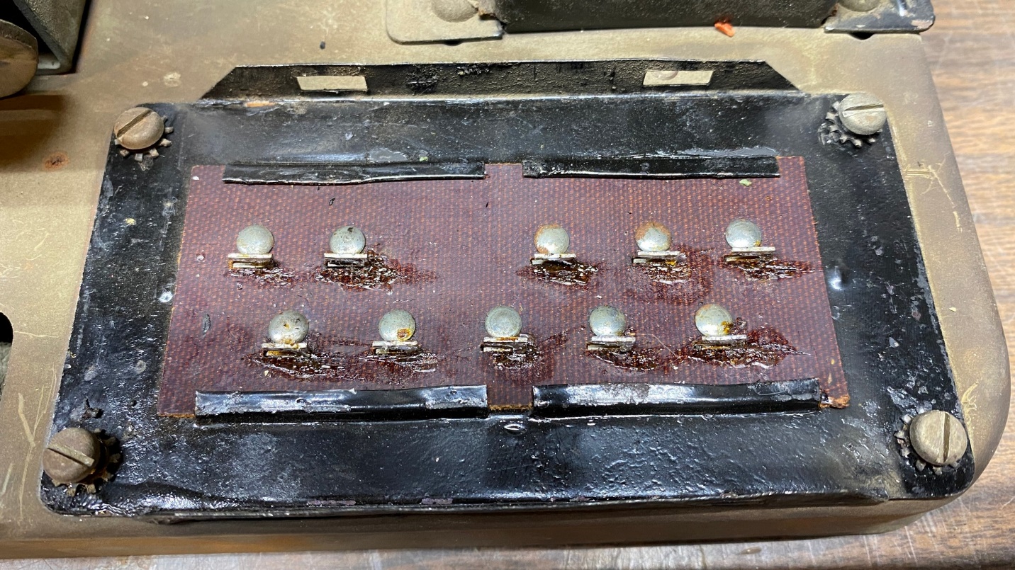
All wires are now removed from the terminal board.
But wait. I am getting a bit ahead of myself. Before proceeding, I need a drawing to show which capacitor connects to what terminal. Fortunately, the service information in the first link at the top of this page includes such a drawing. Here it is in larger size, for clarity:
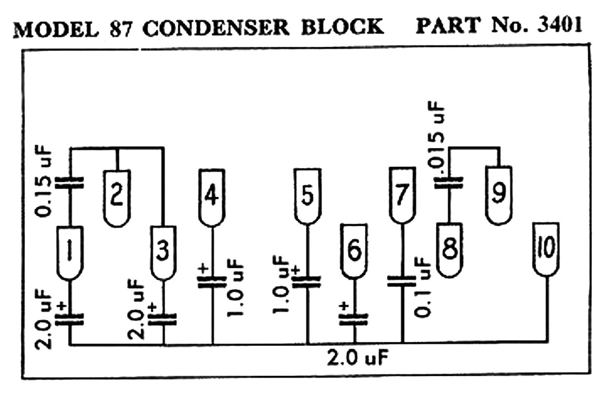
A diagram of the 87’s filter condenser block, as it would be viewed from underneath where the terminals are located.
This shows how things look under the chassis. What I could really use now is a diagram showing how the new capacitors should be connected above the chassis.
I therefore spent some time with my favorite graphics program, and soon had a suitable diagram which I could use.
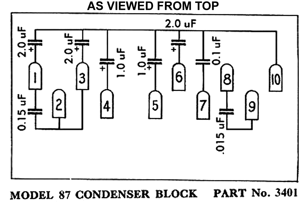
Just what I need to use as I connect the new capacitors to the top of the terminal board.
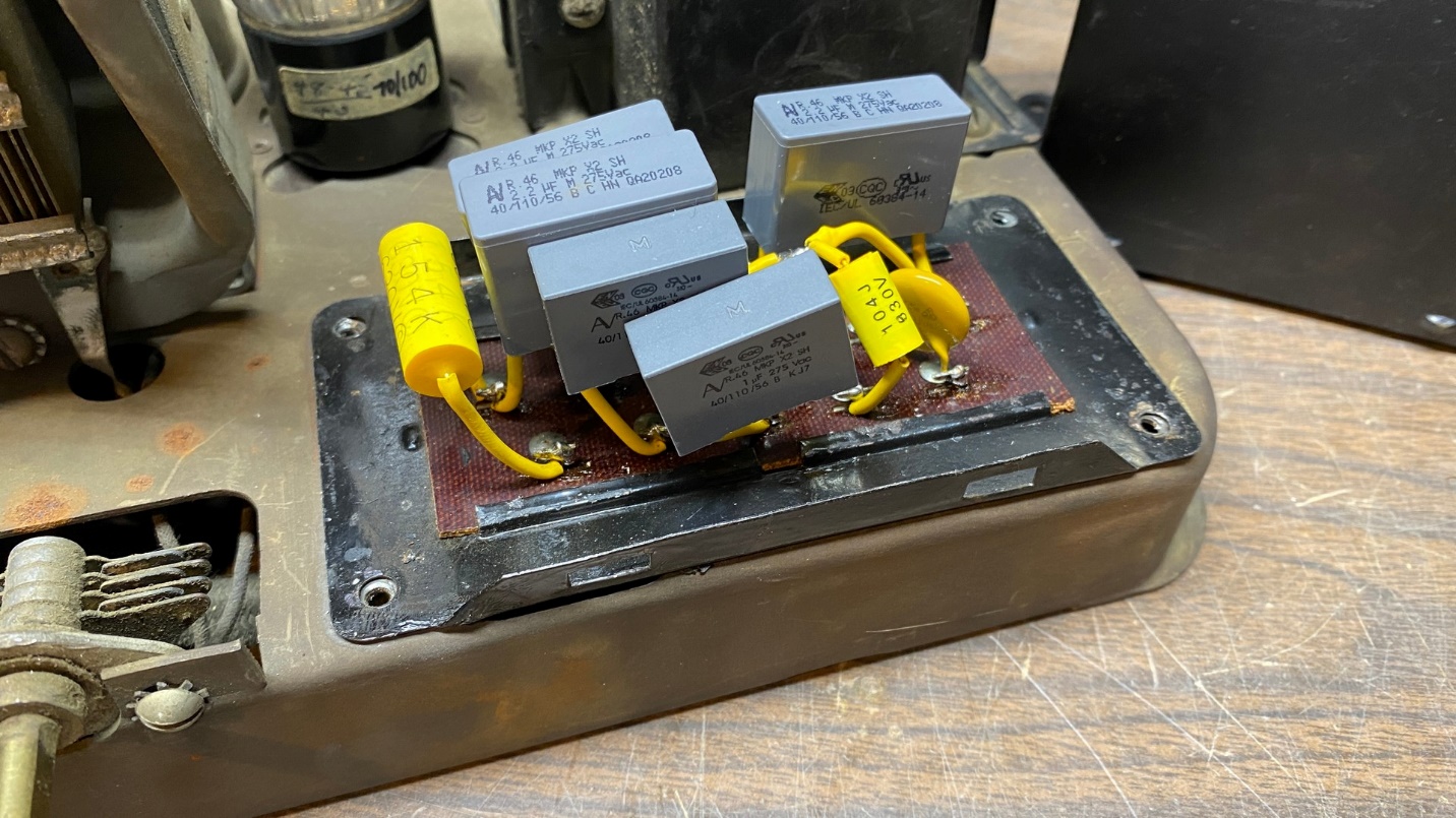
Following this diagram, I carefully mounted all eight new capacitors to the top side of the terminal board.
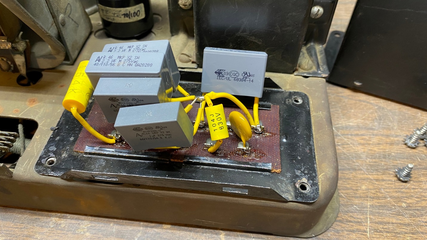
New capacitors mounted on the top side of the terminal board.
The gray 1.0 and 2.2 uF capacitors are polypropylene and are rated at 250 volts AC, but also at 560 volts DC so they should work well as filters. I had a few of these for some reason, so I am using them in this model 87. Electrolytics are not desirable in these early Philcos as they will not withstand a high ripple current, which will result in a premature failure. It happened to me once, several years ago in a model 96, so I was already aware of this issue.
The 0.1 and 0.15 uF capacitors are 630V (DC) yellow film. Finally, the part which is used as a blocking capacitor between one side of the AC line and the LOC terminal next to the radio’s antenna terminal is a 0.01 uF X1/Y2 safety capacitor, designed to fail open. The original capacitor used in this application was 0.015 uF. Using this capacitor and a jumper wire between the radio’s LOC and antenna terminals, the user could use their house wiring as an antenna.
Looking this work over carefully after I finished, I realized that it probably would have been better if I had mounted everything on a perfboard, and then used wires from the perfboard to the proper terminals on the terminal board. Perhaps I will do that on the next early Philco that I have to service.
Now, what to do with this mess?
Now, I need to melt out the old capacitors and the tar from the upper part of the can. That will have to wait until next time, since I no longer have the small propane torch that I once had years ago for jobs such as these. The torch was probably lost in one of my moves. I shall have to buy another and then I may proceed – next time.