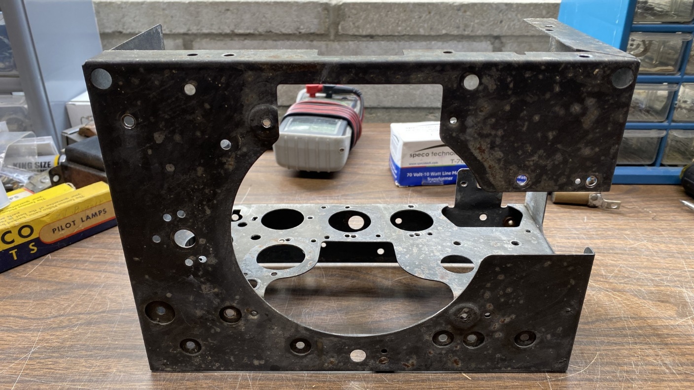
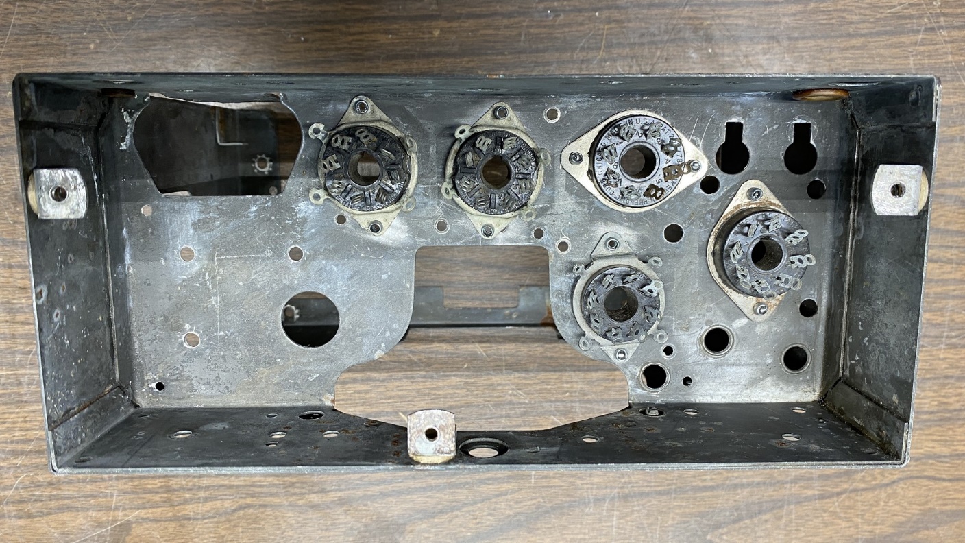
Returning to this Philco model 54 chassis, I removed all the remaining components. Then I began to remove the tube sockets, one by one, by carefully drilling out the rivets which held them in place. Once this was done, I was left with a completely bare chassis.
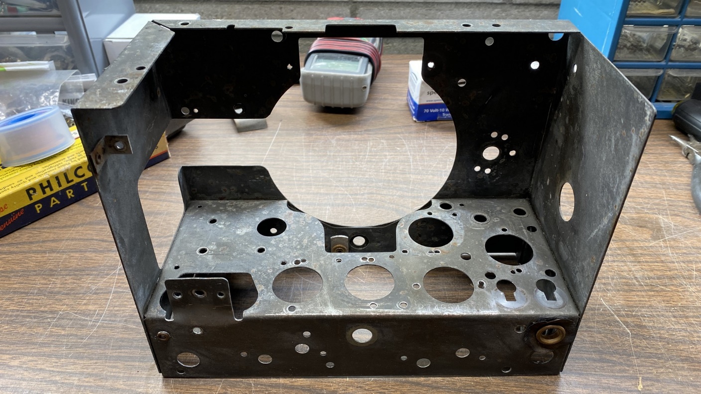
A bare Philco 54 chassis. All parts have been removed.
The chassis itself was in good condition. I went ahead and cleaned it using Go-Jo hand cleaner (the kind without pumice) and dried it with a hair dryer.
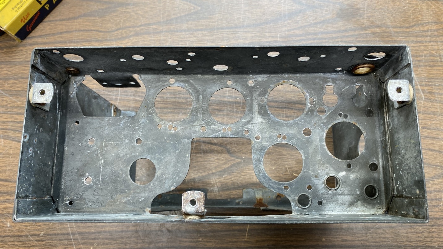
Underside of the bare chassis.
I then prepared to install five new-old-stock (NOS) octal tube sockets in this chassis. Philco did not use even spacing for their tube sockets in 1933; instead, they used an off-center spacing. This meant that I had to drill one new mounting hole per tube socket, while reusing one of the original mounting holes.
After drilling the necessary mounting holes, the NOS tube sockets were installed in place with the help of steel pop rivets.
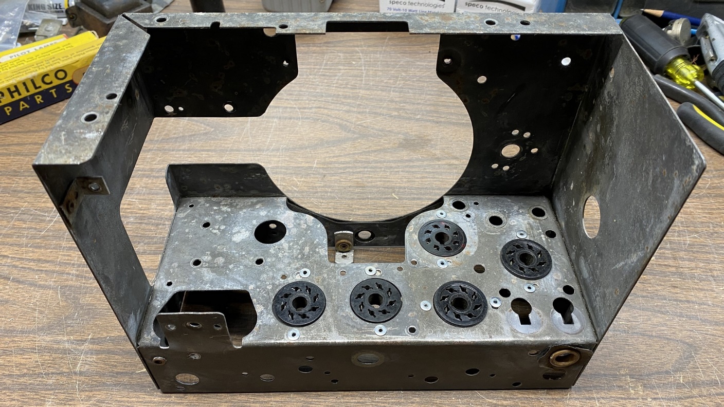
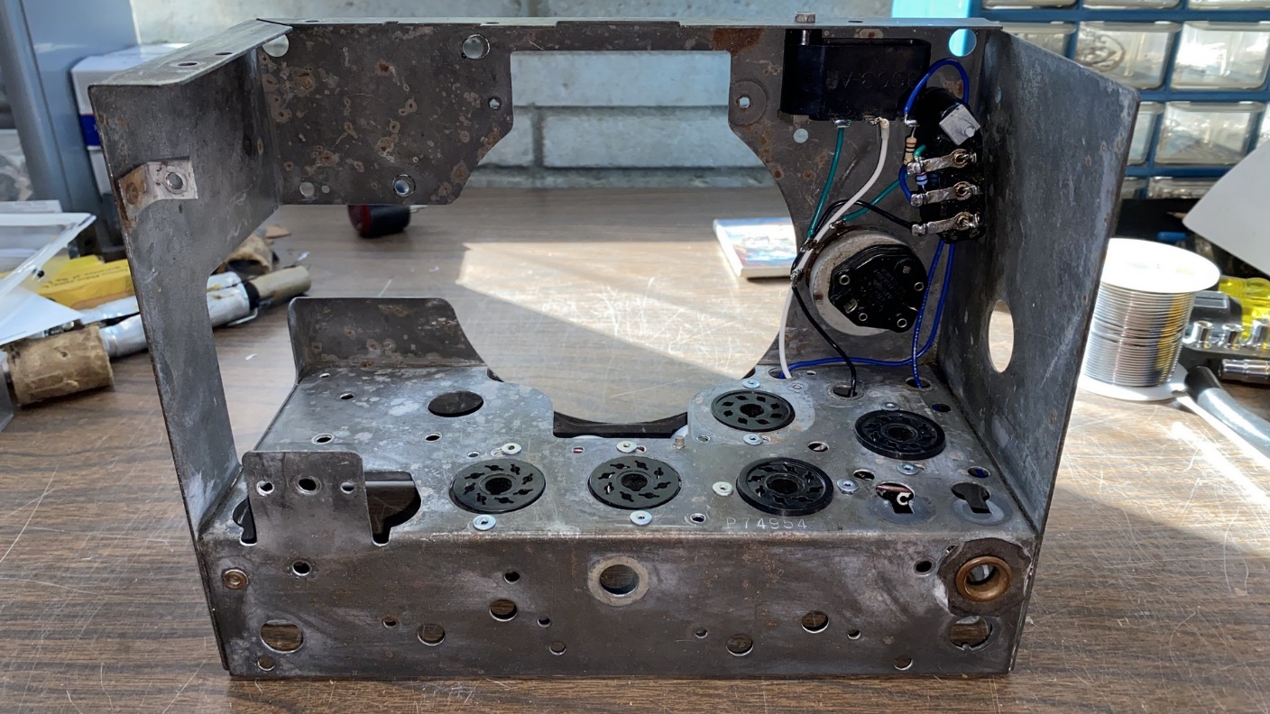
The chassis, after cleaning and after five new-old-stock octal tube sockets had been installed.
Underside of the chassis showing the “new” tube sockets.
You will notice that three of the tube sockets have grounded tie points while the other two do not. I installed the three sockets with tie points specifically for the converter, IF amplifier, and detector – first audio tubes so I could easily tie pin 1 of each of these tubes to ground. This will allow me to use metal tubes in the IF and detector – first audio sockets, as pin 1 of these tubes are connected to their metal shells. This will eliminate the need for tube shields for these tubes.
The converter tube will not require a shield and I will be using a glass tube for this function, but I will tie its pin 1 to ground anyway.
With the sockets in place, it was time to start putting the radio together. However, before I begin that chore, I want to revisit those electrolytic capacitor cans.
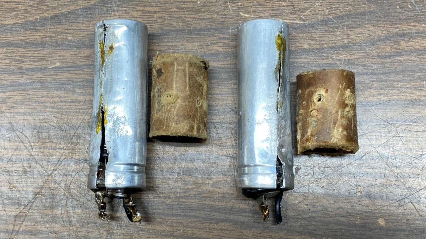
The original electrolytic capacitor cans. They have been virtually destroyed and are unusable.
I wonder why the person who cut these cans did so in the manner in which he or she did? It would have been far, far easier if the cans had been cut horizontally, at the top of the point where the can is narrower. Doing so would have allowed easy reassembly of the can by slipping the top part of the can over the narrow part. Some J-B Weld or other suitable epoxy would have held the parts in place, and the cans would have still looked mostly stock.
Unfortunately, I am not going to be able to reuse these cans.
I advertised for replacements on the two radio forums I frequent – the Philco Phorum and the Antique Radio Forum, or ARF. I did not come up with any suitable substitutes, but a good friend and fellow collector had a pair of twist-lok electrolytics of the proper diameter. He offered to cut the cans off at the bottom and fabricate plastic inserts to go into the bottoms of each. This will be a perfect solution! I accepted his kind offer. Once I receive them, I will stuff them with new electrolytics and install them in the radio chassis.
But in the meantime, I proceeded with reassembly of this 54. I started my work at the audio output tube socket and slowly began to work my way toward the set’s antenna coil.
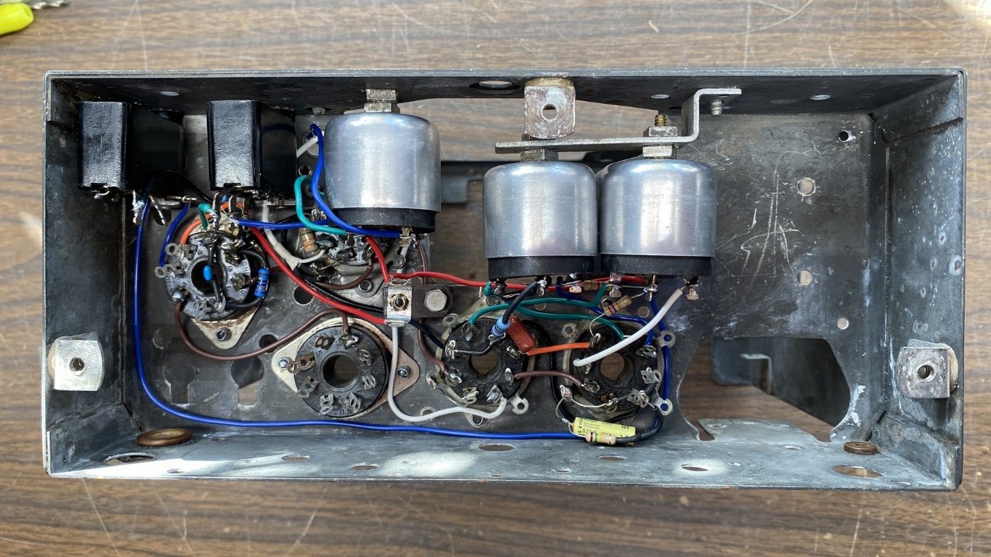
Slowly, I began to wire things up under the chassis. After a few days’ work, I had some new components installed on the top and bottom of the chassis.
When it came time to install the 2nd IF transformer, though, I ran into a problem.
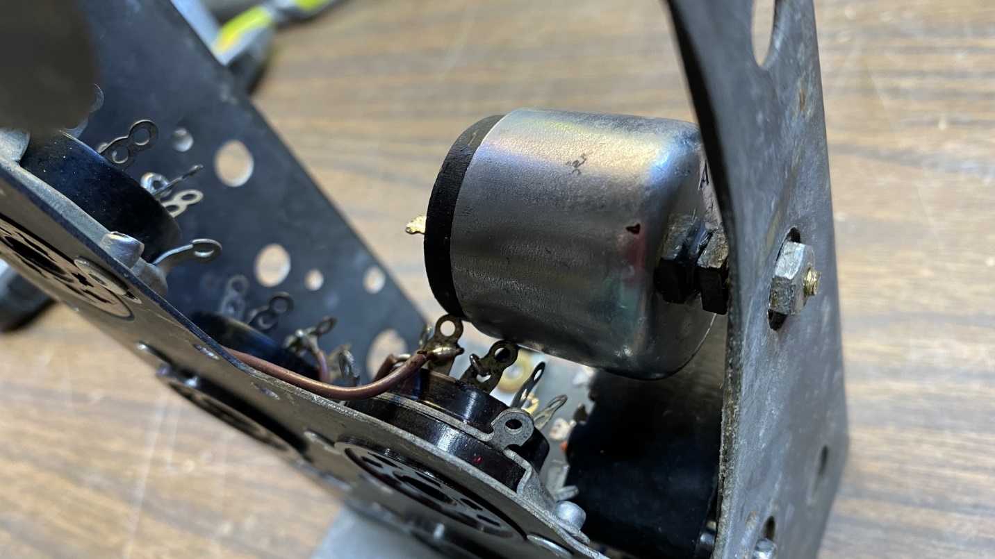
The 2nd IF transformer was making contact with a few of the socket terminals of the 12SQ7 tube.
Take a good look at the picture above. Notice how the 2nd IF transformer can is physically touching two of the 12SQ7 tube socket terminals. I had forgotten that these replacement tube sockets were higher underneath than the original wafer sockets.
Fortunately, the problem was easily solved.
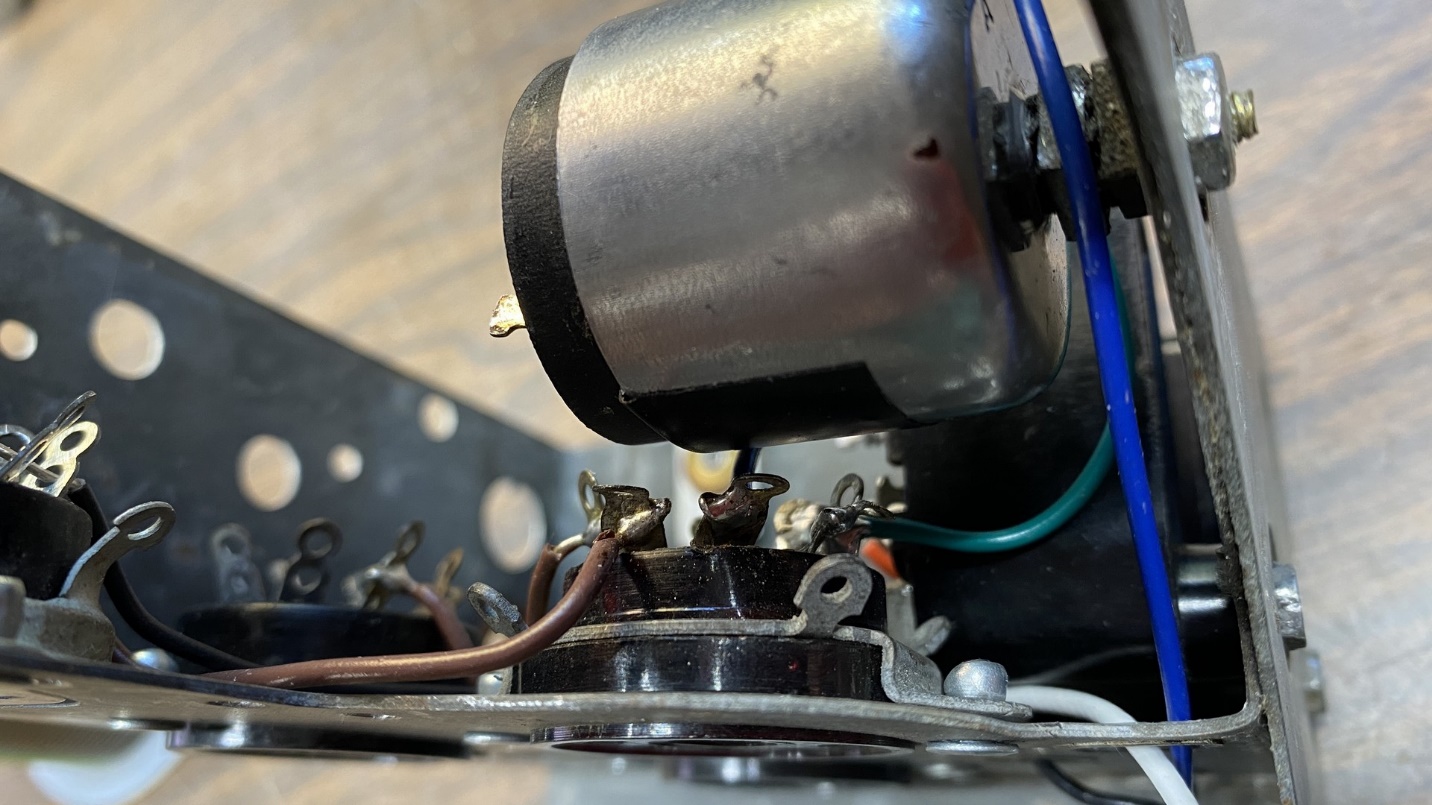
The answer? Bend those contacts out of the way. That was easy!
I carefully bent the offending contacts over, just enough that they would no longer make contact with the 2nd IF transformer can. As extra insurance, I also attached a piece of electrical tape to the can just above where the sockets contacts were located. This should take care of the problem.
After several hours of work, the chassis is starting to look like a radio again.
I continued to work on the chassis over the next few days until I had it at the point where it only needed to have its antenna coil, band switch, tuning condenser, dial lamp assembly, band switch, and speaker reinstalled as you can see above and just below.
The view of the chassis from the top after many of its components had been installed.
Believe it or not, the radio is getting close to being finished other than installation of the components mentioned above. If you look at the two photos above, you will see that this modified chassis is not going to be as jam-packed as the original chassis was. I consider that to be a very good thing.
Next time, I will prepare the tuning condenser for reinstallation and do a few other things as I await the arrival of those replacement electrolytic capacitor cans. So, until then, don’t miss the next installation of this series.