When Philco announced its radio lineup for the 1949 season in mid-1948, the line included a unique model which only had one control and no provision for manual tuning. The 49-901’s single control was a roller which functioned as a combined off-on-volume control and, when pushed down, could select between six preset AM radio stations.
A tiny pilot lamp was provided under the roller which changed colors as different stations were selected.
In recent years, for some strange reason, this radio has acquired the notoriety of allegedly being a “Secretary’s Radio” which was operated with a foot. This is false, and I have no idea how this rumor started. The roller was never intended to be operated with a foot. It was always intended to be used with one’s hand. See the ad below from Philco’s 1949 sales catalog.
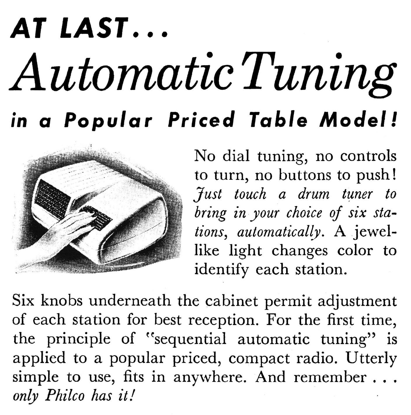
Does that look like someone’s foot in the illustration above? Of course not, it is a hand! In fact, if the roller were stepped on with a foot, the radio would, in all likelihood, quickly become damaged beyond repair.
Philco’s description of the 49-901, from the same 1949 Philco sales catalog, is also enlightening as to its intended purpose.
The Philco 901 with Automatic “Touch Tuning”. Six knobs in bottom of cabinet make it easy to adjust for six selected stations…then tune in any of them at a touch, even in the dark! Philco AC-DC Superheterodyne Circuit. 4 Philco Loktal Tubes, plus rectifier. Permanent Magnet Dynamic Speaker. Improved Built-In Loop Aerial. Beam Power Pentode Audio System. Underwriters’ Approved. Standard American Broadcasts. In Ivory or Light Green Plastic.
So, with proof from Philco itself that the roller control of this radio was intended for touch (hand) operation – not foot operation – put an end to those rumors to the contrary? Not likely. This radio will continue to be called “The Secretary” or “The Secretary’s Radio” in a similar manner to how Philco models 46-420, 48-460 and 49-900 have become known as “The Hippo”.
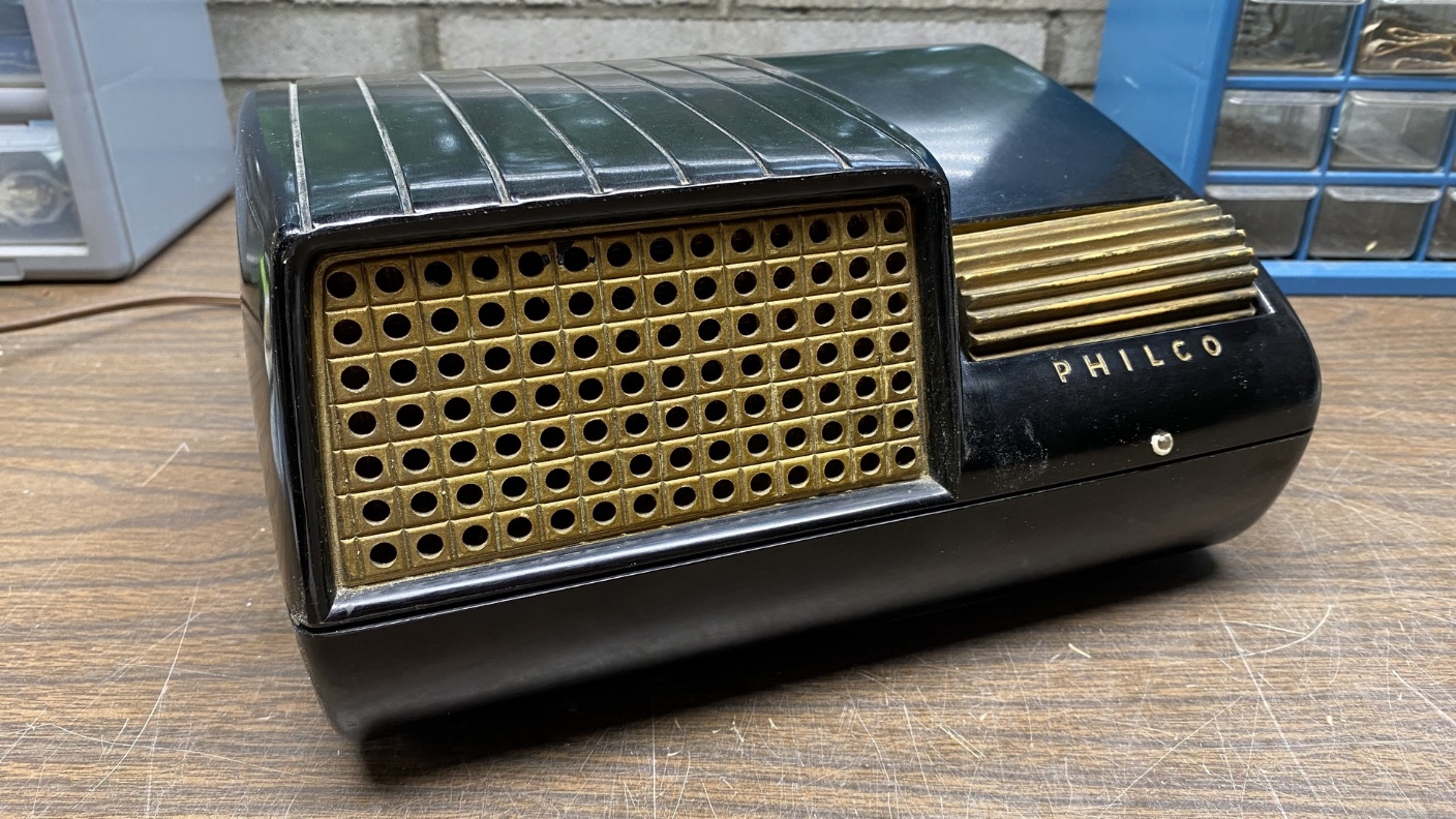
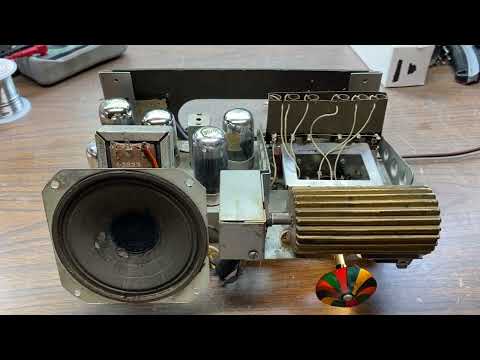
Philco model 49-901, known as “The Secretary”.
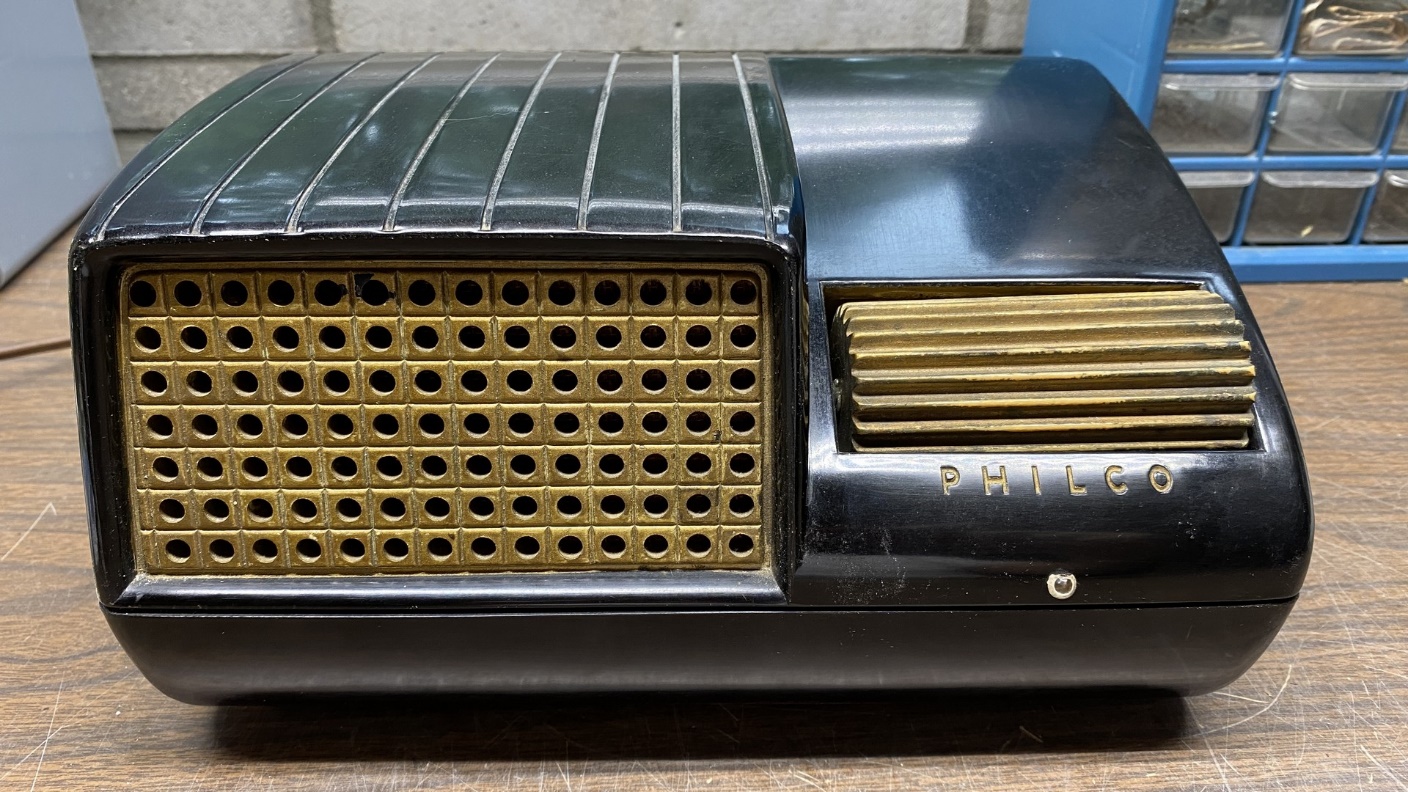
I have had a Philco 49-901 “Secretary” around here for a couple years or so, sitting in a corner, gathering dust. Mine is black Bakelite, with some evidence inside the cabinet of its having been painted a light bluish green at some time in the past. Since Philco only advertised these as being sold in ivory and green, I know the cabinet of mine has been stripped. Someone went to the trouble of repainting the speaker grille in gold, as well as adding gold paint to the recessed PHILCO lettering. It doesn’t look too bad this way, even though black was not an original color.
Recently, I decided I would try to rebuild this little five tube AC/DC radio and get it going.
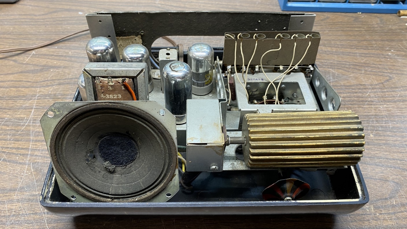
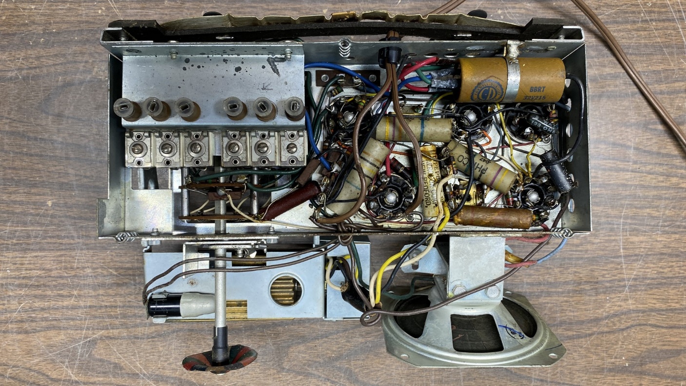
A look at the radio’s chassis after the top of the cabinet had been removed.
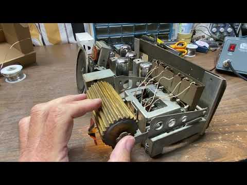
Since the radio did not have a tuning condenser but had a series of individual coils, the set seemed to be a bit simpler in physical appearance than similar conventional radios having a tuning condenser. Looking the chassis over, it did not use a lot of paper capacitors and it seemed like it should be fairly simple to restore.
I did note that the original audio output transformer had been replaced with a Stancor replacement unit. The original three-section electrolytic has been replaced with another electrolytic capacitor. Overall, the radio looked like it had been used a lot in its time.
How the underside of the chassis looked prior to the beginning of its restoration.
Since things were jam-packed under the chassis, I decided not to restuff any paper capacitors to save space. Actually, I could not restuff any of the original Philco capacitors even if I had wanted to, since all were encapsulated in plastic and were not rebuildable.
The recapping went fairly smoothly. I replaced about half of the set’s resistors, but left the rest in place. I would come to regret this decision later.
I replaced C100 with a .01 uF X1/Y2 safety capacitor. Safety capacitors are designed to fail open instead of shorted. As I have mentioned in previous blog posts, it is far better for a capacitor which is connected across the AC line to fail open rather than shorted. A shorted AC line is never a good thing.
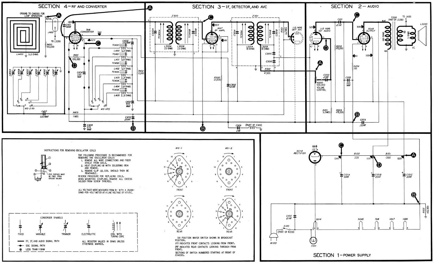
Modified Philco 49-901 schematic (see text).
I also changed the wiring of the radio’s power switch so it would control the hot lead of the set’s AC line instead of the neutral side as originally designed. When these radios were being manufactured, it was thought that switching the neutral side of the line would reduce the chance of additional hum in the radio. However, it is safer to switch the hot side of the line. Since this radio is an AC/DC set, one side of the line will always be energized. Again, it is safer to place the power switch in the hot side of the line. Light switches in homes switch the hot side of the line, never the neutral side. The same should be true of radios.
The slightly modified 49-901 schematic shown above documents the changes made to C100 and the placement of the power switch.
When I made it to my final step, which was rebuilding the three-section electrolytic, I found that I had no 22 uF electrolytics but had several 33 uF, 200 volt Panasonics on hand. So, I used three 33 uF electrolytics instead of one 33 uF and two 22 uF units.
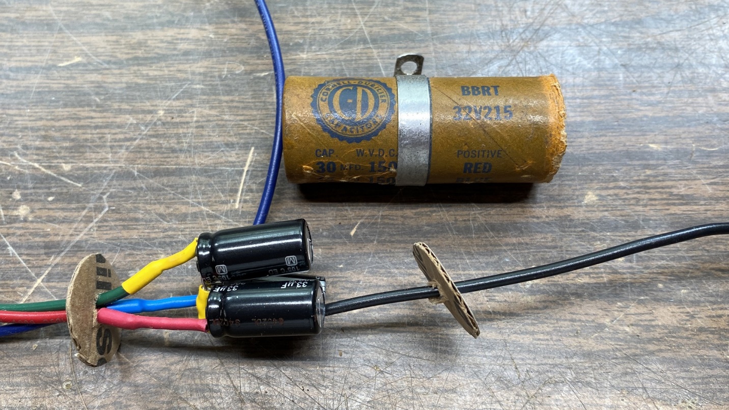
Three new Panasonic 33 uF, 200 volt, low ESR electrolytics were used to replace the old capacitors within the Cornell-Dubilier package.
The three Panasonic electrolytics just fit inside the old fiberboard package of the long-ago replacement Cornell-Dubilier electrolytic capacitor. I cut two round pieces out of a cardboard box to use as end covers for the electrolytic package. Once the new capacitors were sealed inside the container, it almost looked original except for the somewhat sloppy job I did of sealing the cardboard ends of the container with hot glue.
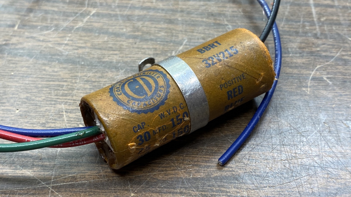
The restuffed three-section electrolytic capacitor.
After doing a quick and dirty IF alignment (in other words, by ear instead of using a VTVM as an output indicator) and getting the six preset channels aligned to six AM stations with the help of my signal generator, I tried it out with my home AM transmitter, an SSTRAN operating at 660 kc.
Unfortunately, it did not perform very well. The radio was only picking up my home SSTRAN as well as a local station in nearby Jasper, Indiana, and those were coming in very weakly with very distorted sound complete with hum modulation.
I had previously tested all the tubes, and two which were weak were replaced. I also scraped the pins of each loctal tube with a knife, and sprayed each tube socket contact with DeoxIT, working the stuff into each contact with the aid of a cleaning brush intended for use between one’s teeth. The volume control was also given a shot of FaderLube.
Here is a sample of how it sounded initially:
At this point I stopped and sought advice on the Philco Phorum, an online forum for collectors of vintage Philco radios. The side effects of all the chemotherapy I have had over the past few years had me second guessing myself by this point, so I did not want to make any mistakes because of that. Soon after receiving some helpful suggestions, I sat down and took a good look at the chassis of this radio.
First, I checked the loop antenna connections as had been suggested. I remembered after reading that suggestion that an improperly connected loop antenna would result in garbled reception with hum modulation. However, the loop was properly connected as it should have been, so that was not the issue.
I had not replaced some of the resistors. It was then I remembered that this radio appeared to have been used a lot. And then I thought about the resistors which I had not replaced. Therefore, I set out to replace many of the resistors I had not replaced initially.
When I was done, all the resistors save two (R204, which had been replaced in the past, and R403 which was mounted on the selector switch) had been replaced. In addition, I went ahead and replaced four of the mica capacitors in the tuning circuit (C401, C402, C404 & C405). I did not trust C405 as it looked like a “dogbone” resistor with thin, fragile leads.
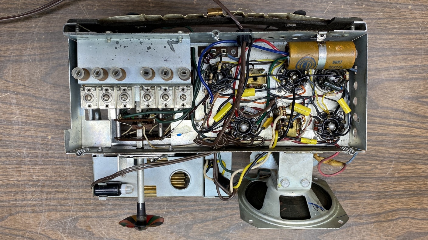
How the chassis looked underneath after replacement of all paper and electrolytic capacitors, most resistors, and most of the mica capacitors.
After replacing those parts, I tried the radio out again. Would it work correctly now? Let’s find out.
The first station you hear is WITZ in Jasper at 990 kc. The 1280 preset was silent, but then my home SSTRAN comes in loud and clear at 660 kc. No longer did the volume control need to be at maximum to hear my SSTRAN. Most importantly, the sound was no longer garbled, and the hum modulation was also gone!
Lesson remembered: In an old AC/DC radio such as this that has obviously seen heavy use, don’t stop at replacing the paper and electrolytic capacitors. Replace the old resistors as well, and mica caps as needed.
The next day, I redid the 49-901’s IF alignment the right way, using a VTVM as an output indicator. Following this, I readjusted the preset station frequencies as follows:
1 – 660 kc – my home SSTRAN
2 – 840 kc – WHAS, Louisville, KY
3 – 860 kc – WSON, Henderson, KY
4 – 990 kc – WITZ, Jasper, IN
5 – 1280 kc – WGBF, Evansville, IN
6 – 1420 kc – WVJS, Owensboro, KY
I also replaced the speaker and output transformer with a speaker that has a nearly perfect cone with no holes, and only one very minor visible tear which I can easily fix with fabric glue. Its attached output transformer was made for a 50C5 which will also match the loctal 50A5 used in the 49-901.
After making these changes, I put the chassis through its paces once again as may be heard in the video below:
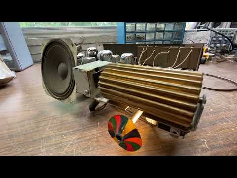
I think it sounds somewhat better now with the replacement speaker.
In the video above, you will notice that six stations can be heard – three (WHAS, WSON, WVJS) are very weak. Two (my SSTRAN and WITZ) are strong. One (WGBF) is sort of in the middle as far as signal strength is concerned. My basement is not a good place for AM reception.
That is it for this 49-901 chassis restoration. Thanks for following along. I’ll have another electronic project to present here in the near future.