Yes, it has been a while since I have done anything with this project. With other projects on the back burner, I need to get moving on this one and get it completed as soon as I can so I can move on to others.
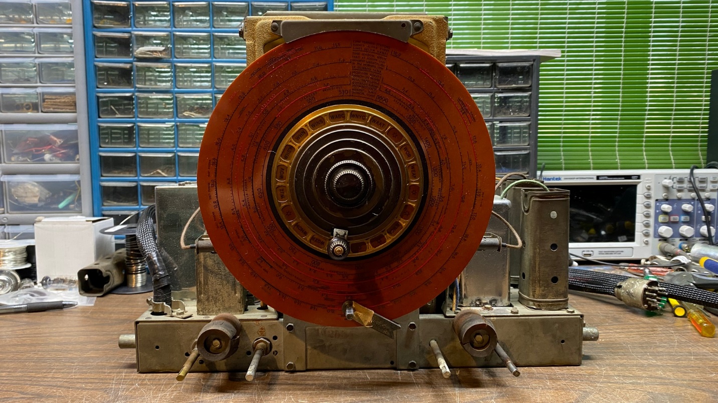
The photo above shows the front of the upper chassis of the subject Philco 38-690. I pulled it out in preparation to remove its RF unit and do an autopsy on it to find out why it had been smoking, and from where the problem had been occurring.
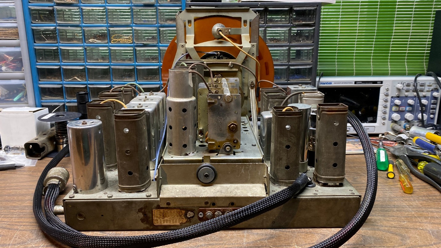
Back view of the 38-690 upper chassis.
As you can see, the upper chassis has two all-new wiring harnesses with all-new wires inside the looms. The chassis is clean, and the dial scale is a new reproduction from Radio Daze. This is the same dial used in the 38-116, and Radio Daze sells it as a 38-116 replacement.
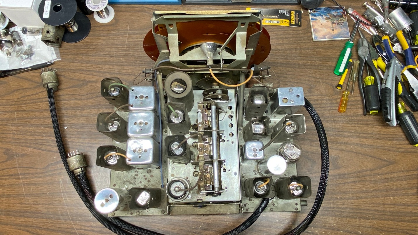
Upper view of Philco 38-690 chassis.
A look at the chassis from above. Yes, I used to own this radio, and I went to the trouble of cleaning and polishing all the aluminum cans when I owned it.
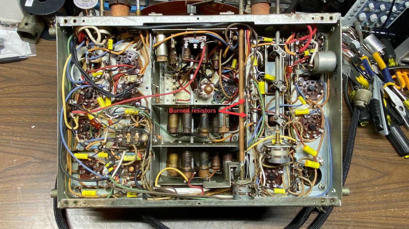
38-690 upper chassis, as seen from beneath.
Finally, a look underneath this chassis. If you look closely just to the right of center, you will see two problems. They are identified in the photo above.
Yes, two resistors are burned. They are resistors (64) and (69) on the 38-690 schematic. Let’s take a closer look:
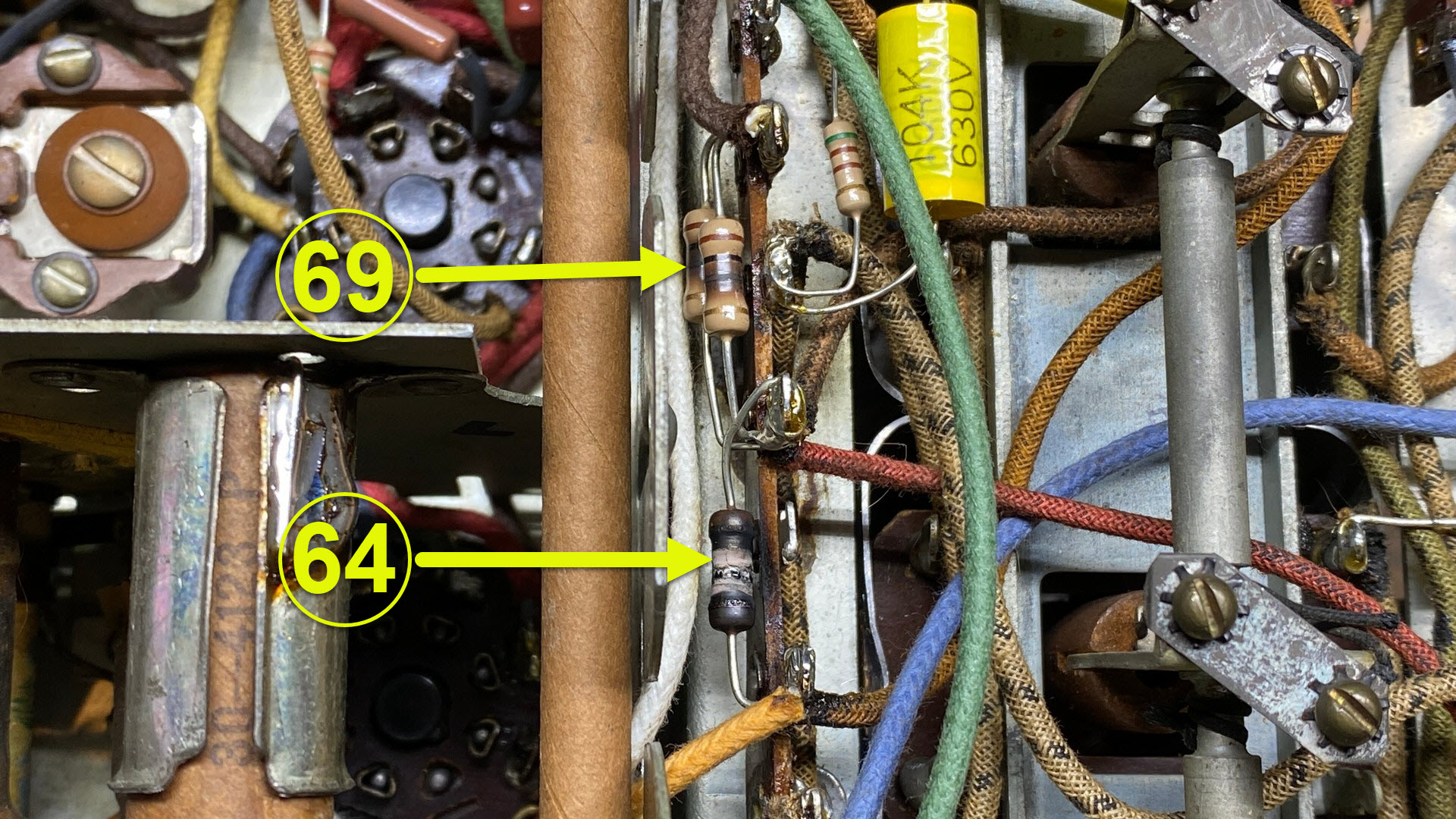
Roasted resistors. Yum! (not)
As you can see, resistor (64), a 1000 ohm ½ watt resistor, is burnt to the proverbial crisp while (69), two 1000 ohm 1 watt resistors in parallel resulting in a 500 ohm 2 watt resistance, shows some obvious burning. This indicates excessive current being drawn somewhere.
A B+ line runs to resistor (69) which then splits off four ways. One leg runs through the primary of the 4th IF transformer (70) to the plate of the 2nd IF tube. Another leg runs through the primary of the 2nd IF transformer (48) to the plate of the 1st IF tube. A third leg goes through the primary of the AVC-IF transformer (57) to the plate of the RF-AVC tube. The fourth and final leg goes directly to resistor (64). From here, there is a two-way split in the resulting B+ fed through resistor (64). One leg goes through the primary of the 1st IF transformer (47) to the plate of the mixer tube. The other leg runs through the primary of RF coil (14) and through switch terminals C4, C8 & C12 to the plate of the RF tube. One lead of the primary of RF coil (17), as well as capacitor (21), are also connected to this leg. And in addition, switch terminals C8 also connects to the plate of the RF tube, which leads to mica capacitor (11).
This is a very interesting situation here, as Jimmy Stewart would say. I do not believe the issue is occurring in the IF or RF-AVC circuits, for if this were the case, resistor (64) would not be charred as it is. The heavy current draw is likely occurring at some point to the left of resistor (64) as viewed on the schematic. It could be a carbon track on wafer C of the band switch, as I have suspected all along, or it could be a short in capacitors (11) or (21), or even in coils (14) or (17).
I plan to do some resistance tests before I remove the RF unit, but I suspect I will not find the fault until I remove the RF unit, remove the RF section which includes switch wafers C and D, and do a full inspection.
The problem could even be a carbon track in the tube socket of the RF tube, from the plate contact to a ground point. I had previously replaced that socket. Hmmm…something to think about for certain. Of course, the RF tube socket is part of the RF unit.
Yes, I could probably just pop in the 37-116 RF unit I recently rebuilt, replace resistors (64) and (67), perform an alignment, and all would be well. But I want to know what went wrong in this RF unit and correct it if I can. Next time, we will remove this RF unit and start digging into it.
Until next time!