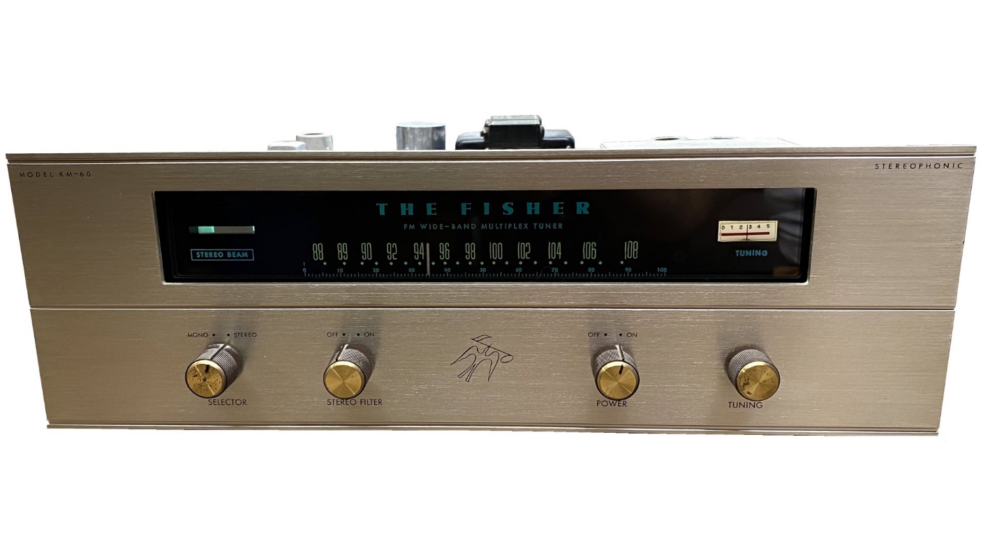
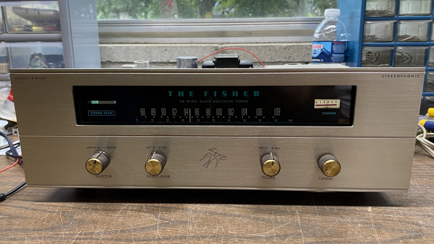
Around the beginning of this year, as you may recall, I acquired a Fisher model KM-60 StrataKit FM Stereo tuner. This tuner was offered in kit form to allow those prospective owners which either could not afford a factory-built Fisher, or did not want to spend $200 or more for one of Fisher’s better tuners at the time, to own a quality FM Stereo tuner if he or she had a knowledge of basic electronics and possessed the ability to properly use a soldering gun and follow directions.
The Fisher model KM-60 StrataKit FM Stereo tuner.
Having checked date codes on the tuner’s IF transformers, I had previously determined that this particular StrataKit likely left the factory in early Spring 1964, as the latest date code on its IF transformers is 64-09 which equals the 9th week of 1964. This would be the last week of February of that year.
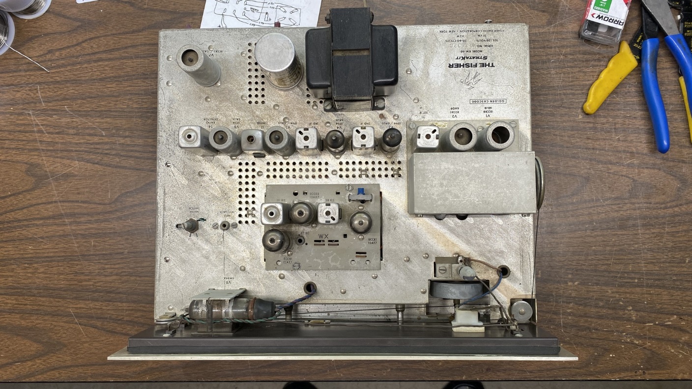
Top view of the KM-60’s chassis.
I was very fortunate in that this tuner arrived here with all its knobs in place. So often, vintage Fishers are missing knobs, and they can be very expensive to replace.
Whoever originally assembled this kit tuner did an exceptionally good job. All the solder joints were done well, and parts placement and wiring also looked very good.
This tuner has been sitting around since January. With a break in my home improvement projects, I decided to replace the critical components (paper and electrolytic capacitors and the bridge rectifier) in this KM-60 in October of this year.
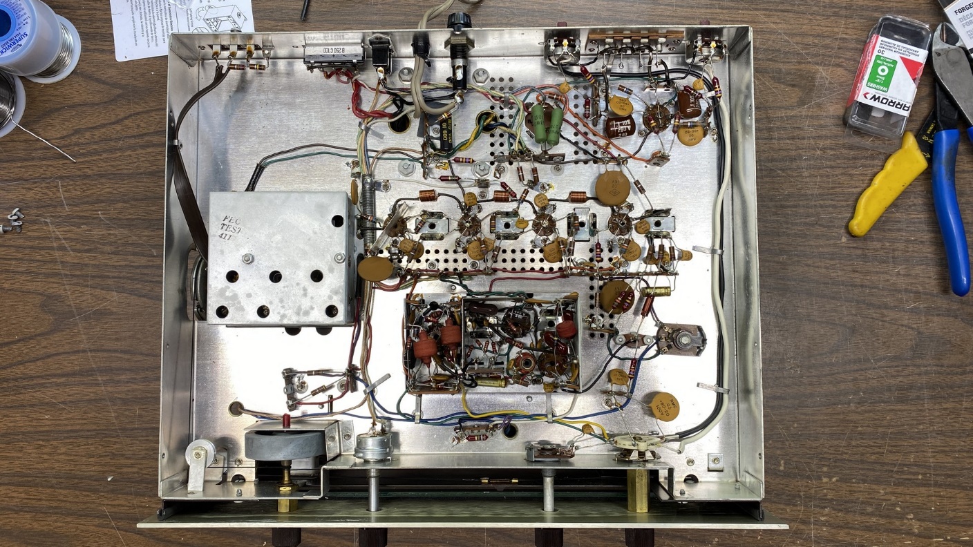
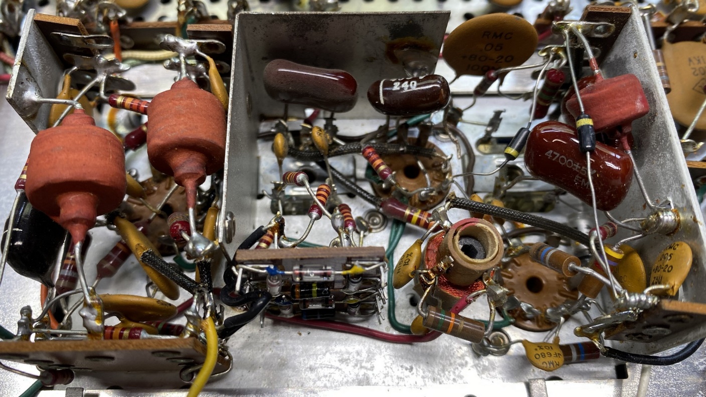
Underside of the KM-60 chassis.
As I have stated before in previous Fisher restoration articles, I do not have a set place to begin; I always pick a spot arbitrarily and just dive into the work.
This time, I chose to begin at the tuner’s FM multiplex decoder.
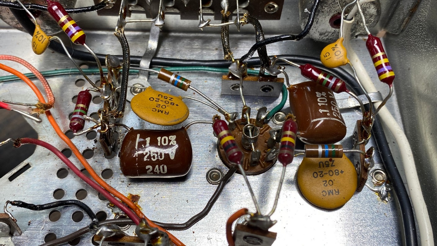
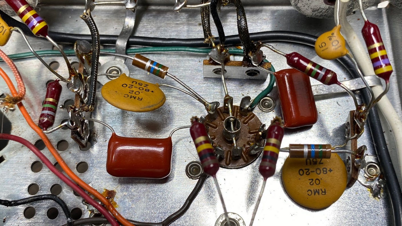
The WX multiplex decoder used in the KM-60. The 1 uF electrolytic has already been removed, in preparation for its replacement by a film capacitor.
I replaced the 1 uF, 300 volt electrolytic in the multiplex decoder with a 1 uF, 350V film capacitor. This is much larger than the original, but it should have a very long life.
There is a .0047 uF brown “dog turd” capacitor within the decoder. This was replaced by a new .0047 uF, 630V unit.
I still have not restocked on the radial polypropylene .047 uF capacitors, so I left the .047 uF “dog turds” in the decoder for now. I will replace those later. Since this tuner was working when it arrived here, I was not too concerned about not replacing those.
In my zeal to get this tuner completed, I forgot to take an “after” photo of the multiplex decoder. I was working rather quickly as I expected to have surgery later that week. However, the surgery ended up being postponed.
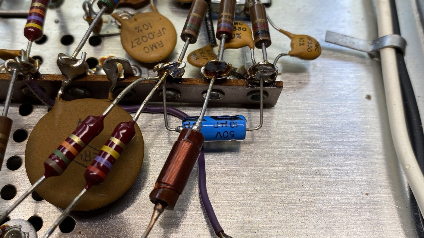
New 10 uF electrolytic in the ratio detector circuit.
Next up was the 8 uF, 50V electrolytic in the ratio detector circuit. This was soon replaced by a new 10 uF, 50V electrolytic as shown above.
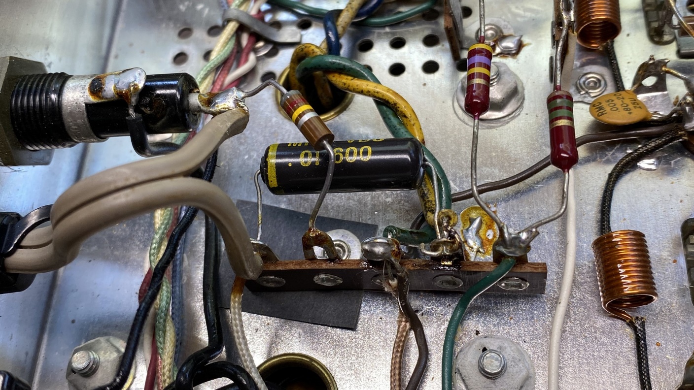
The old AC line or “death” capacitor.
There is usually one capacitor connected between one side of the AC line and ground in these vintage Fisher tuners. This tuner had a “black bumblebee” .01 uF capacitor in this position. It is unsafe to use conventional capacitors as AC line bypass units, because they could fail either open or shorted. If they failed shorted, one side of the AC line would be connected directly to the chassis which would be a very unsafe situation. This is why they are often referred to as “death” capacitors.
Today, we have safety capacitors which are designed to fail open only. These come in X1, Y1, Y2 and other configurations including a universal X1/Y2 designation which are very handy if the hobbyist wishes to stock only one type of safety capacitor.
In case you are curious, type X capacitors are designed to be connected across the line, while type Y capacitors are to be connected from line to ground.
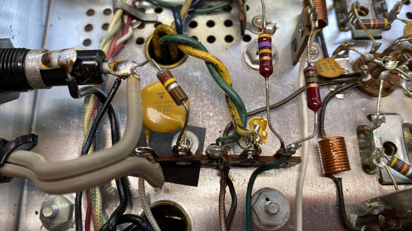
A new Vishay .01 uF X1/Y2 safety capacitor is now in place of the old “black bumblebee”.
It did not take long at all to unsolder and remove the old “bumble bee” capacitor and solder in a new Vishay .01 uF X1/Y2 safety capacitor in its place.
With that done, I turned my attention to the bridge rectifier.
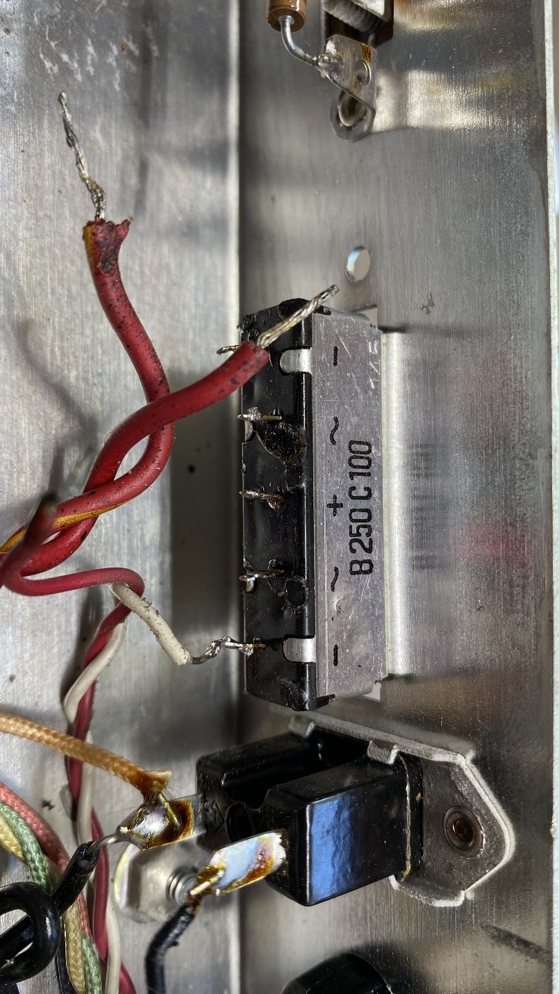
Original Siemens bridge rectifier.
The original bridge rectifiers were made by Siemens of Germany. They are made of selenium and are subject to failure at any time. When selenium rectifiers fail, they give off a strong odor which is also toxic. I did not wish to deal with that possibility, so the old Siemens rectifier needed to go.
Once again, I forgot to take an “after” photo. But if you have been following my Fisher tuner restorations, you know by now that I usually replace these with a 1000 PIV, 10 amp silicon bridge rectifier. Yes, as I have mentioned previously, I know these are overkill for this purpose. However, I like the idea of those solder lugs – they make convenient solder terminals for the necessary wires.
Two more “dog turd” capacitors in the audio preamp circuit.
I did not wish to forget the two 0.1 uF “dog turd” capacitors in the audio preamp circuit. After some careful unsoldering, these were soon replaced by radial 0.1 uF, 630V polypropylene capacitors. These somewhat resemble the originals, which is why I use them in Fisher tuners. In addition, they take up much less space than the equivalent axial yellow film capacitors.
New replacements – 0.1 uF, 630V polypropylene capacitors.
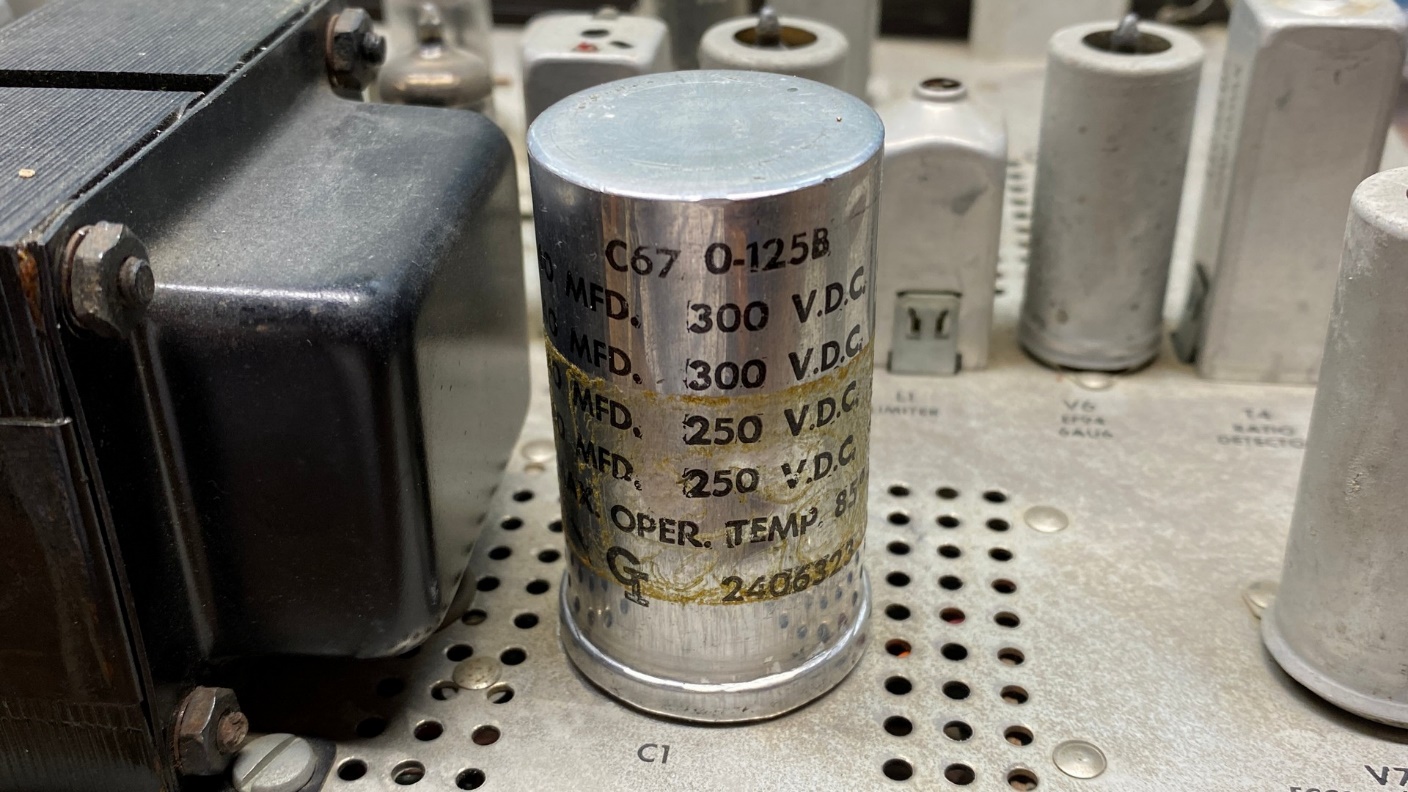
Finally, it was time to tackle my least favorite job of working on vintage Fishers – the four-section twist-lock electrolytic capacitor.
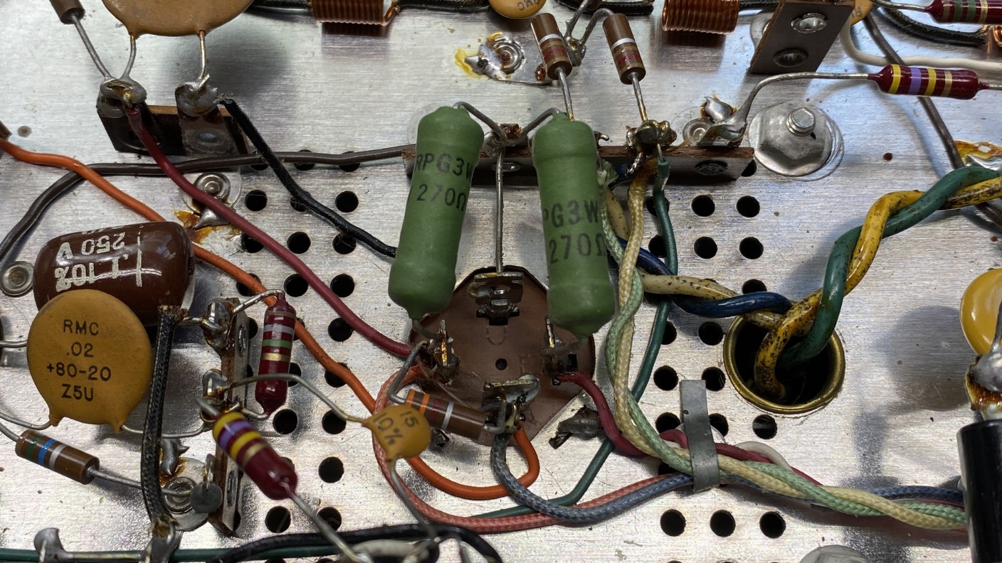
The main filter capacitor can from underneath, with two 270 ohm power resistors.
I removed the two 270 ohm resistors and all the wires which you see in the photo above, and then proceeded to unsolder two of the four lugs which hold the capacitor in place. Once the lugs had been unsoldered, I carefully untwisted them and removed the capacitor.
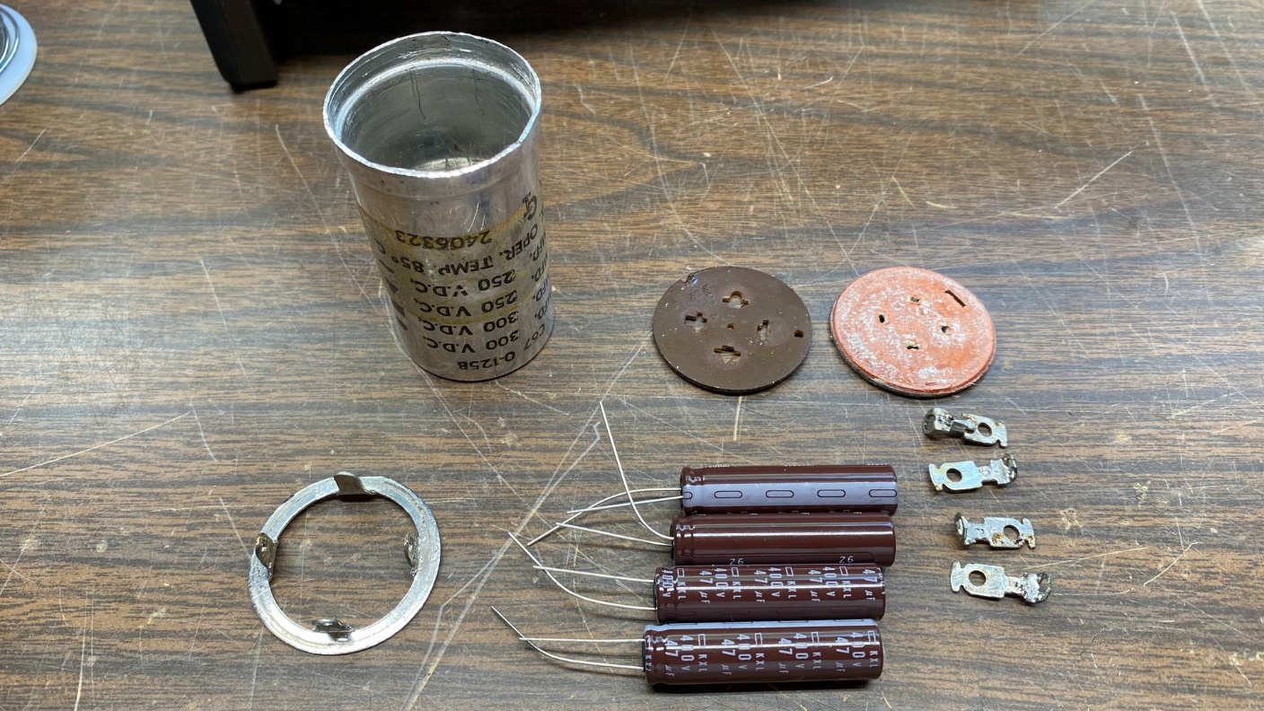
The electrolytic can is ready to be restuffed with new electrolytics.
I opened the can as I usually do, by carefully cutting off the lower lip of the can. Next, I cleaned the can out and then prepared four United Chemicon 47 uF, 400V electrolytics rated at 105 degrees C.
Before long, I had everything put together and reinstalled in the can. Using my heavy duty needle nose pliers, I carefully rolled the lip back over so the can appeared much as it did originally, with the newly rolled lip holding everything in place inside the can.
The restuffed electrolytic can is reinstalled in the KM-60 chassis.
As I had done with the previous Fisher tuner I had restored – an FM-100-B – I did not retwist the lugs, but instead used solder once again on two of the four lugs to hold the can to the chassis.
Next came reattachment of the various wires to the proper places. The old 270 ohm resistors were replaced with new 330 ohm power resistors, since the silicon rectifier has a higher B+ output than the old selenium rectifier did. This will keep the set’s B+ voltage under control.
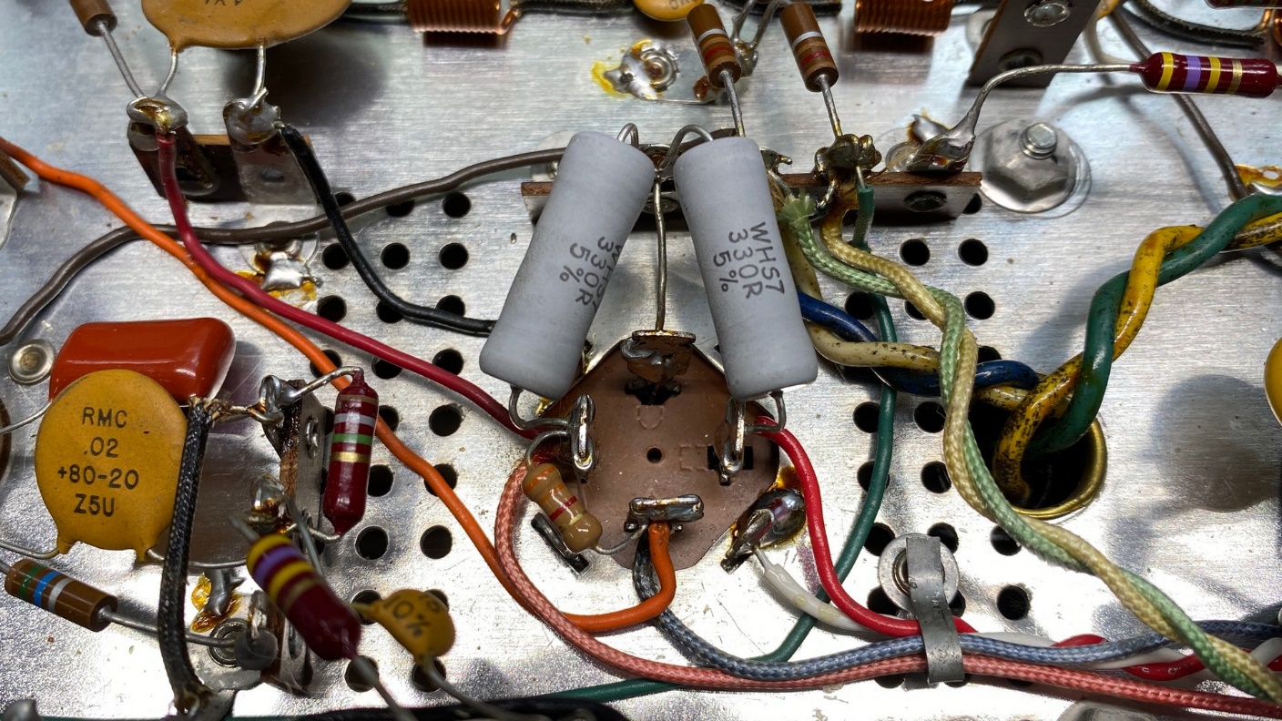
The restuffed electrolytic is now in place. New 330 ohm power resistors are used to replace the original 270 ohm resistors.
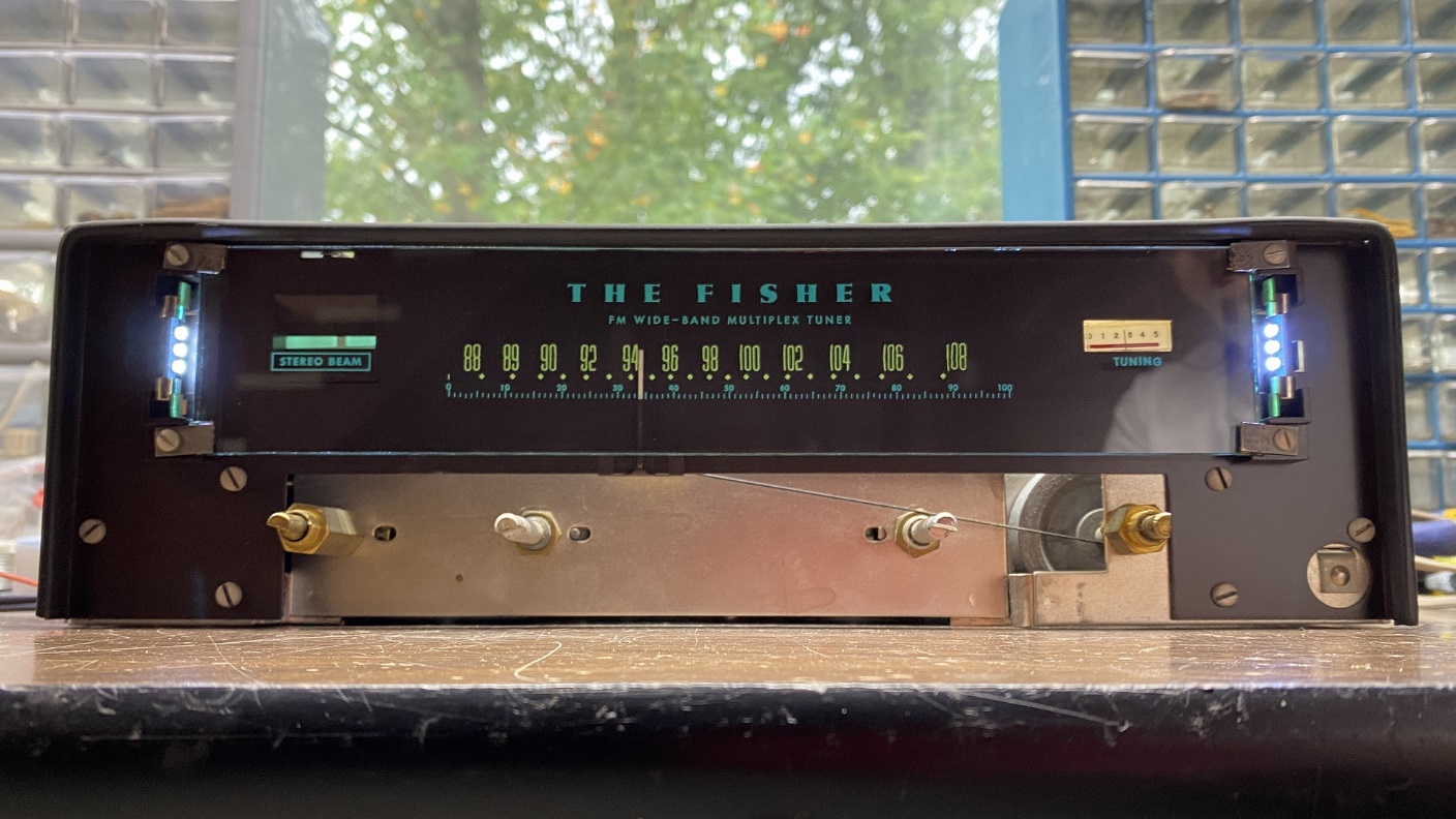
I had noticed that the dial glass needed to be cleaned. But there was something I had not noticed before – the dial numbers (in megahertz) had a “drunk” appearance. See below.
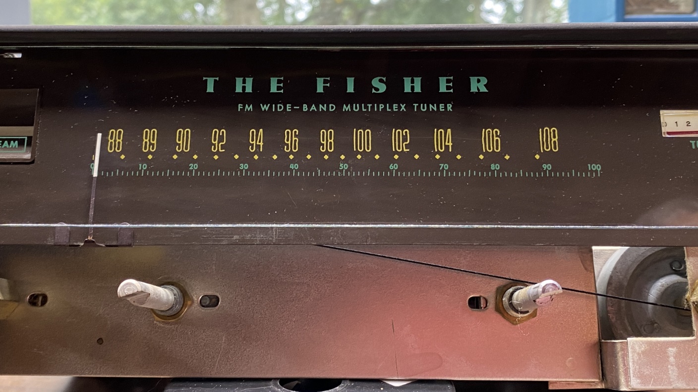
The frequency numbers on the dial have a “drunk” appearance.
Most likely, this was caused by the tuner having been stored in a hot, humid environment at one time, possibly in an attic. The numbers are not too bad, though, and I can live with them. I have seen these numbers migrate all over a glass dial. The only fix in that instance is replacement (if a replacement is available).
I cleaned the glass as I normally do. I removed the glass from the tuner and carefully placed it on a folded towel, face up. Next, I sprayed some glass cleaner on a soft rag and cleaned the front side of the glass.
When that is finished, I flip the glass over so the back side is up. Now, with a tissue, I carefully breathe on the glass, a section at a time, wiping the breath off the glass with the tissue as I go along. I tried to be extra careful this time due to the condition of the frequency numbers. Fortunately, these were not bothered by the careful cleaning, and I soon had a clean glass dial scale which was then remounted on the tuner.
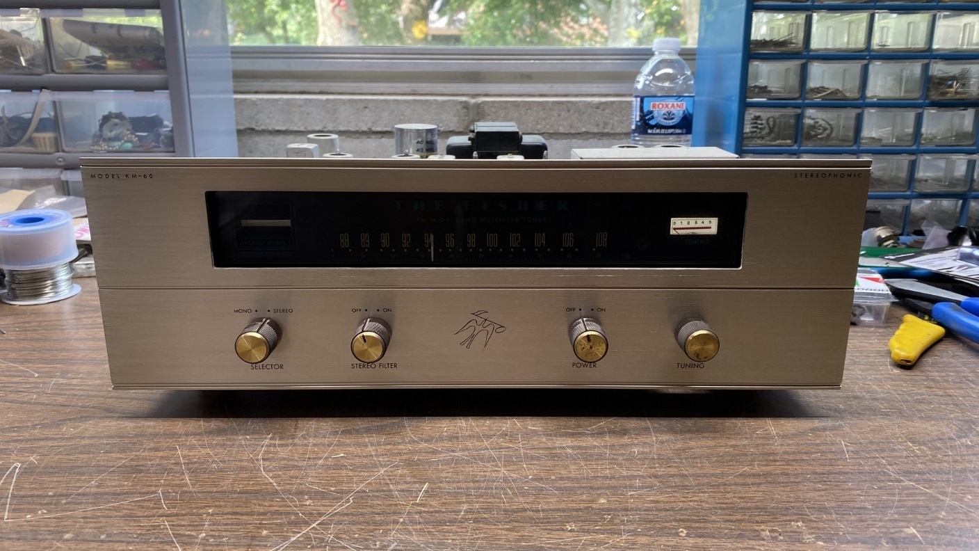
The tuner is tried out for the first time after electronic repairs.
With electronic repairs complete on this tuner and the dial scale freshly cleaned, I decided it was a good time to try the tuner out before I reattached its bottom cover and front panel.
Connecting a temporary antenna to it and connecting the tuner to my workbench amplifier, it was soon receiving the typical local and nearby FM radio stations without issue.
It is going to require alignment, however. I noticed that every FM radio station was coming in around 1 MHz low on the dial. For example, 92.5 showed up at 91.5; 95.5 at 94.5; and 104.7 at 103.7. I will take care of that later.
The finished product – a rebuilt and working KM-60.
Other than the necessity of an alignment, this tuner was now complete, and it should be in good shape for many more years.