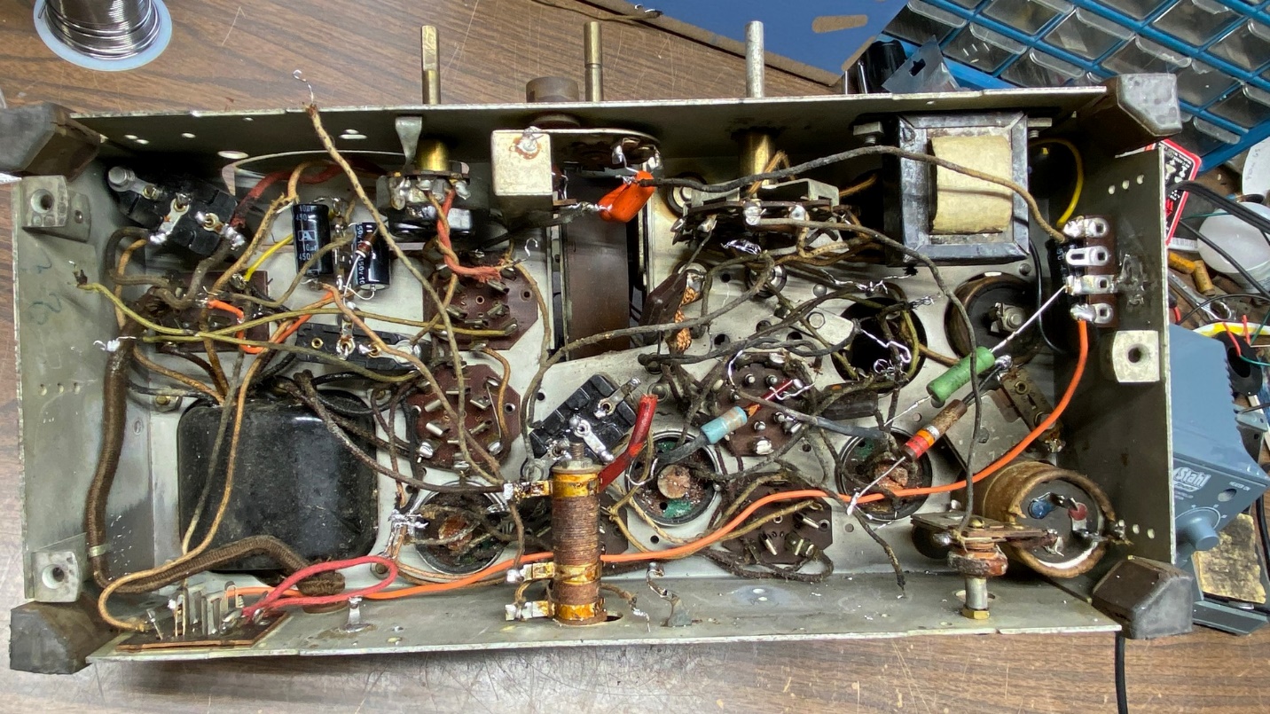
A view under the chassis after both terminal boards had been removed.
The slow teardown continues.
With both terminal boards out of the chassis, I could now take a better look under there and see just what else I would need to do to this radio.
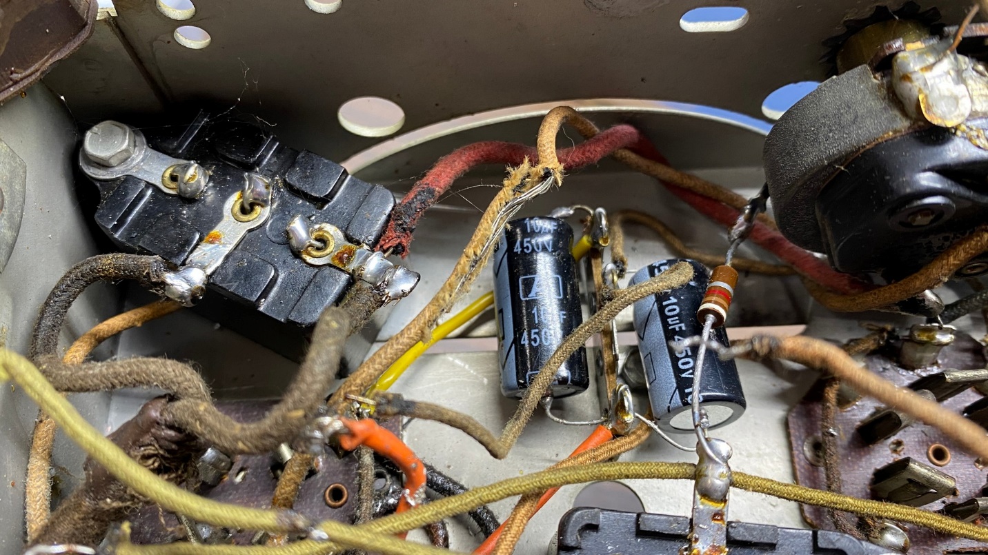
Two electrolytic capacitors sloppily installed under the chassis. A bare transformer wire can also be seen.
I had previously mentioned the replacement electrolytic capacitors. The previous repair person also replaced the paper capacitors inside the three-point tone control. As you can see in the photo below, the work was done very sloppily.
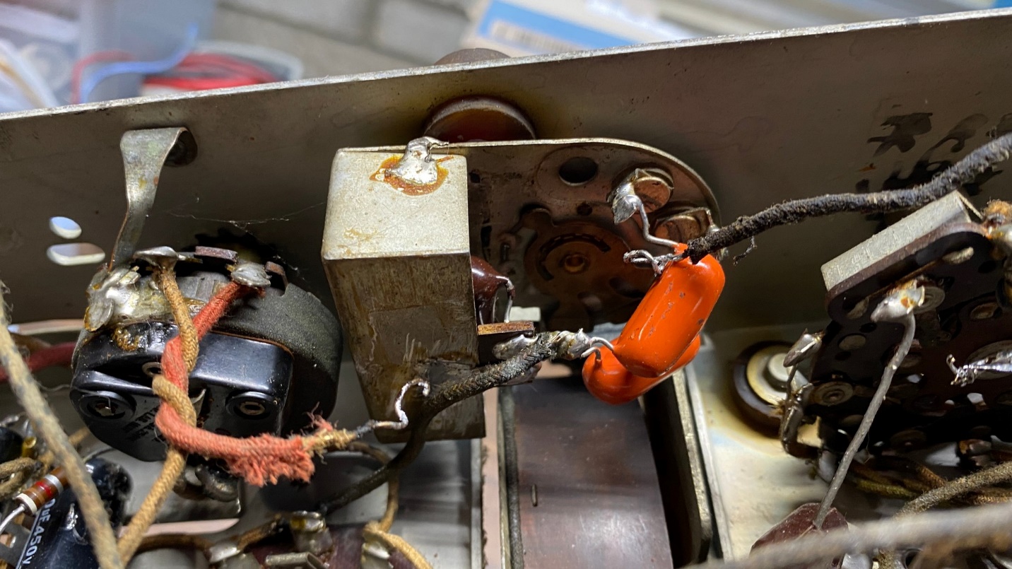
A poorly rebuilt tone control.
With today’s miniature film capacitors, it is very easy to properly rebuild a Philco tone control and make the repair look authentic at the same time. I selected some metalized propylene capacitors which are even smaller than they yellow film capacitors to use in the tone control.
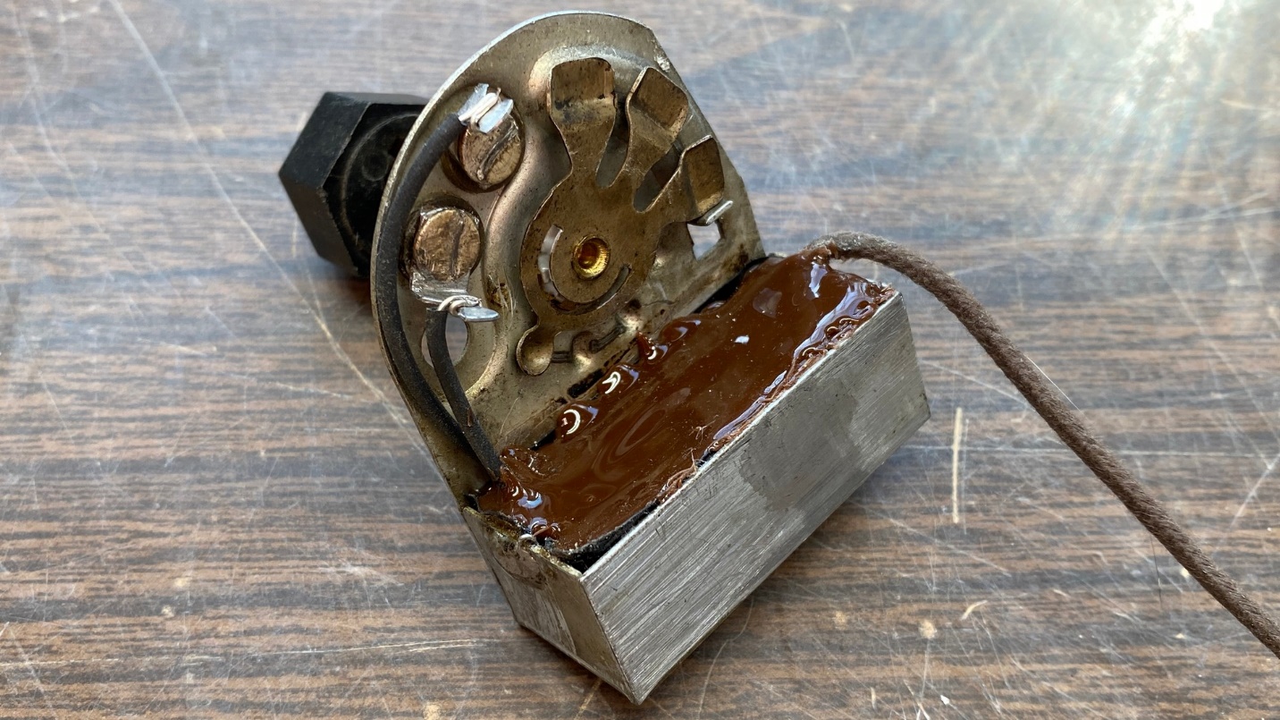
The restuffed tone control.
Philco tone control capacitors are encased in a waxy substance, which is wrapped in fish paper and installed into the tone control. The fish paper had been removed from this tone control, so I had to improvise. I lined the inside of the metal tone control shell with electrical tape, and then installed the new capacitors with a cloth-covered wire which would eventually connect to the plate terminal of the 42 output tube.
For the finishing touch, I filled the cavity of the tone control with brown hot glue to, once again, give the unit a mostly original appearance.
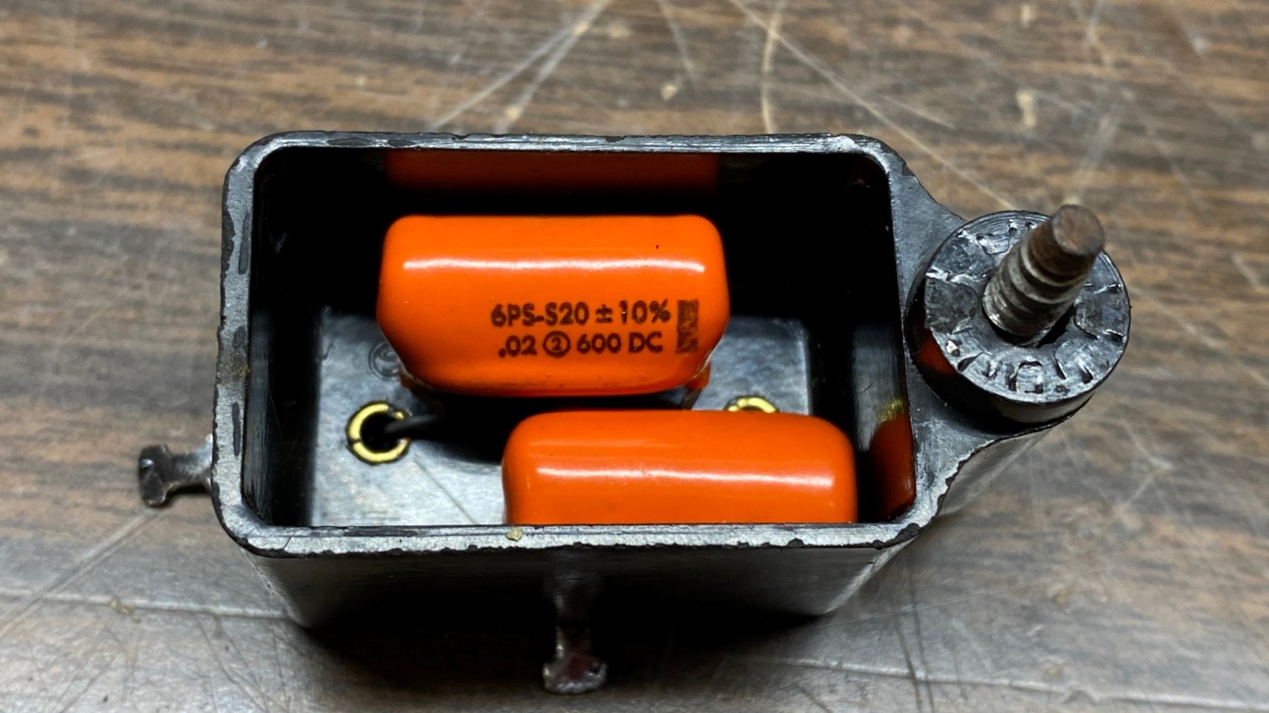
The AC line bypass Bakelite block capacitor.
Next, I removed the three Bakelite block capacitors used in this radio. As it turned out, all three had been restuffed previously. However, the Bakelite block used as an AC line bypass had Sprague Orange Drops inside.
These days, with X1/Y2 safety capacitors readily available and reasonably priced, there is no excuse not to use these when capacitors are connected either across the AC line or, in this instance, between each side of the AC line and the chassis.
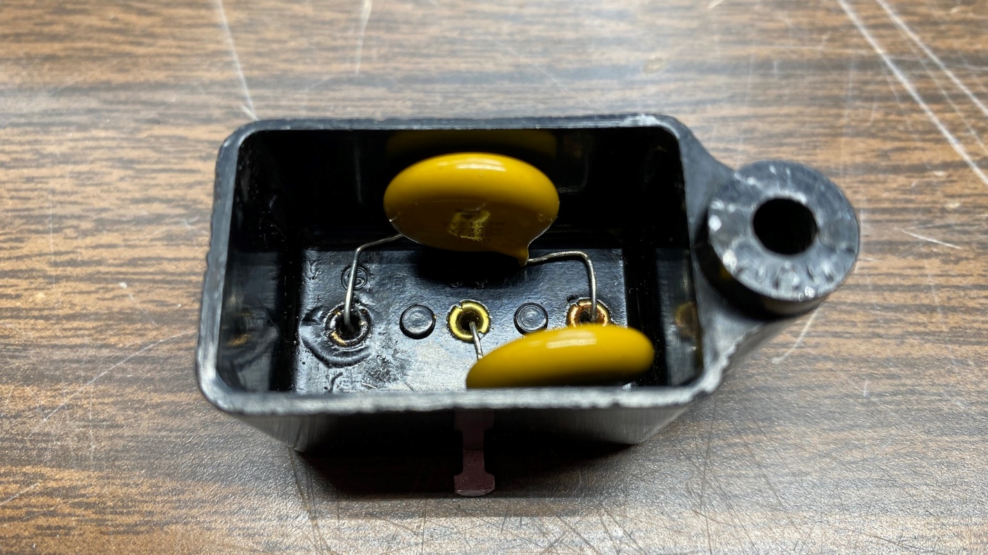
The same Bakelite block capacitor, now using X1/Y2 safety capacitors.
Although not really necessary, I always fill the AC line bypass Bakelite block capacitors I restuff with hot glue. It just gives me a better feeling to know those capacitors have plenty of insulation since they are connected across the AC line.
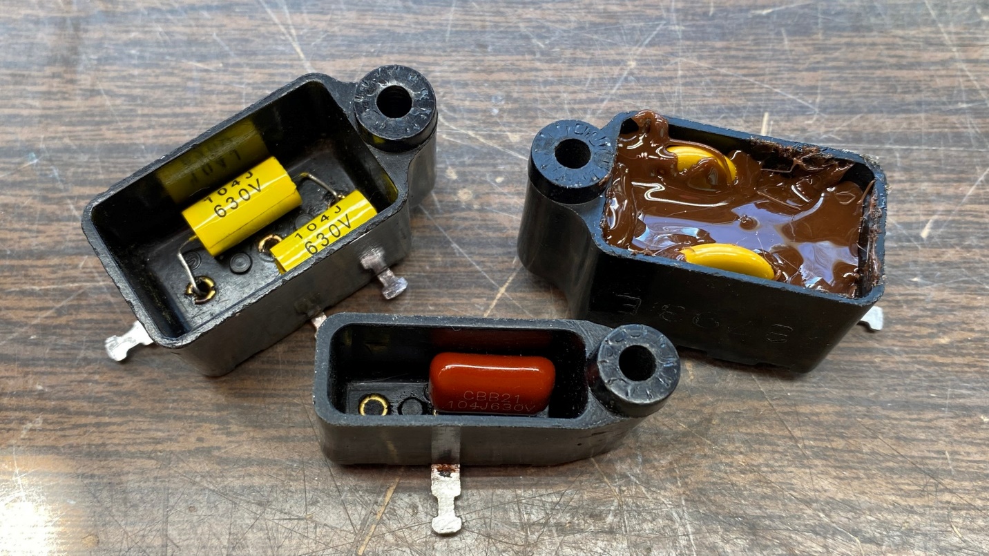
All three of this radio’s Bakelite block capacitors now have new capacitors and are ready to be reinstalled in the chassis.
Before long, I had all three Bakelite block capacitors restuffed with new capacitors and they were ready for reinstallation in the chassis. I would not be putting them back in right away, however.
I took a good look at the radio’s three IF transformers. The wires from each of these appeared to be in rough shape. I decided to remove these to rewire them.
This was quickly turning into a very large job that was about to get even larger. Next time, I will show you what I decided to do with the chassis, and also take care of some more issues. Stay tuned.