A mistake made, a lesson learned.
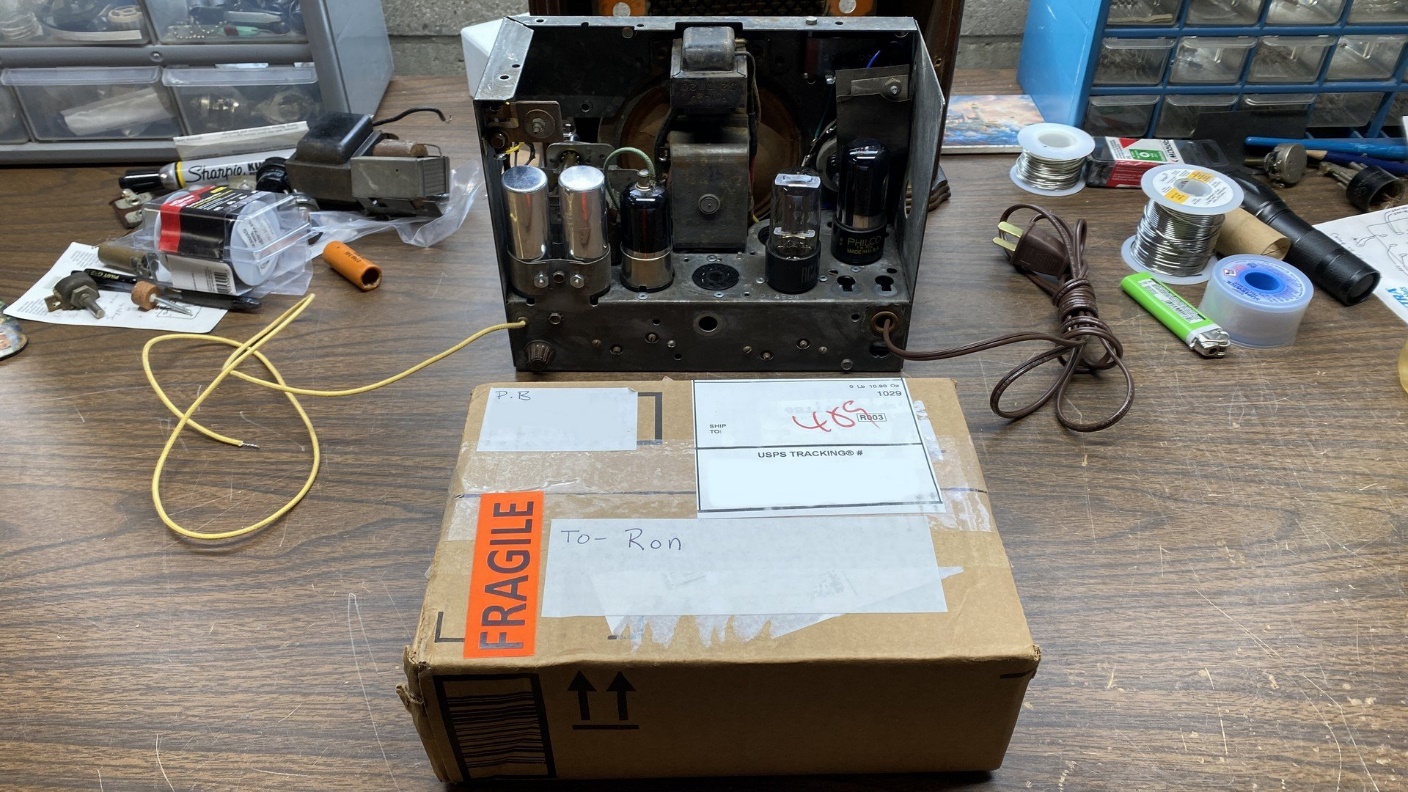
The tubes I had been waiting for from my friend Paul had arrived. I opened the box to find that he had sent not just one, but two each of the two tube types I needed so I would have a couple spare 12SK7 and 12SQ7 tubes. This was certainly appreciated, as I may want to do another such conversion to a radio in the future.
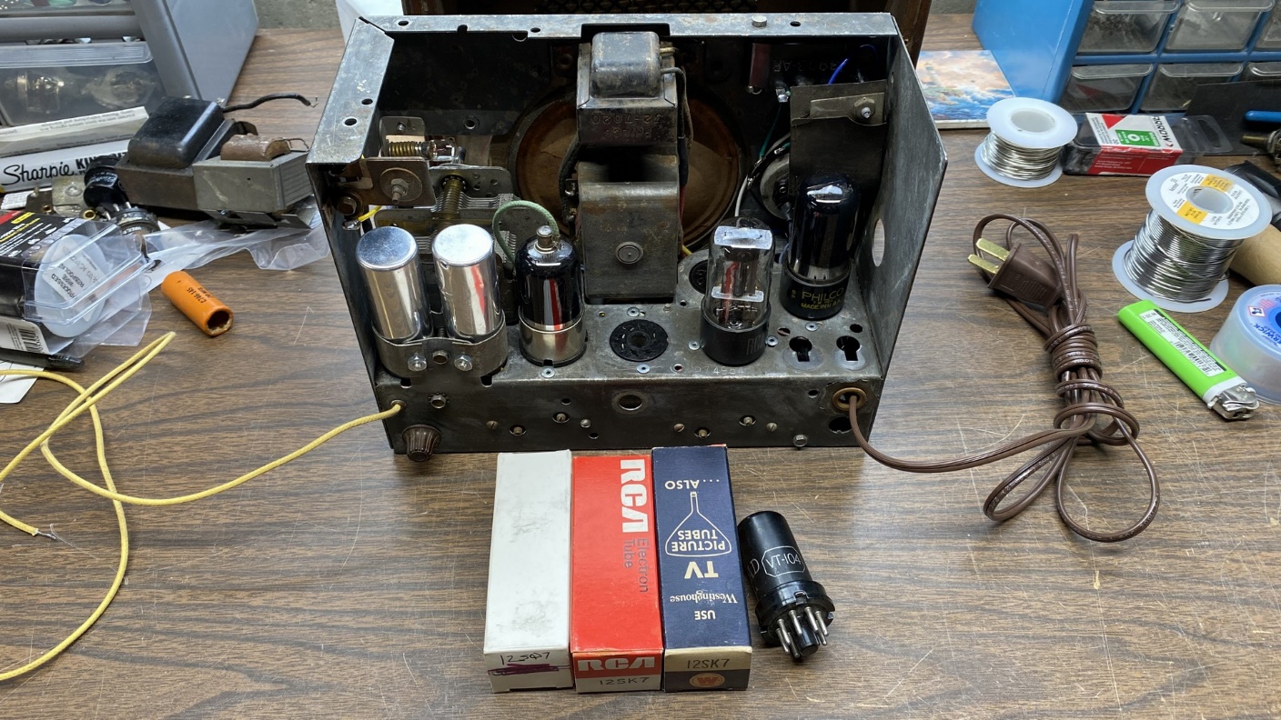
Four new tubes have arrived from my friend in Massachusetts.
But in the meantime, let’s focus on the project at hand. I installed two of the tubes into my customized Philco 54C, and put the spares away for safe keeping.
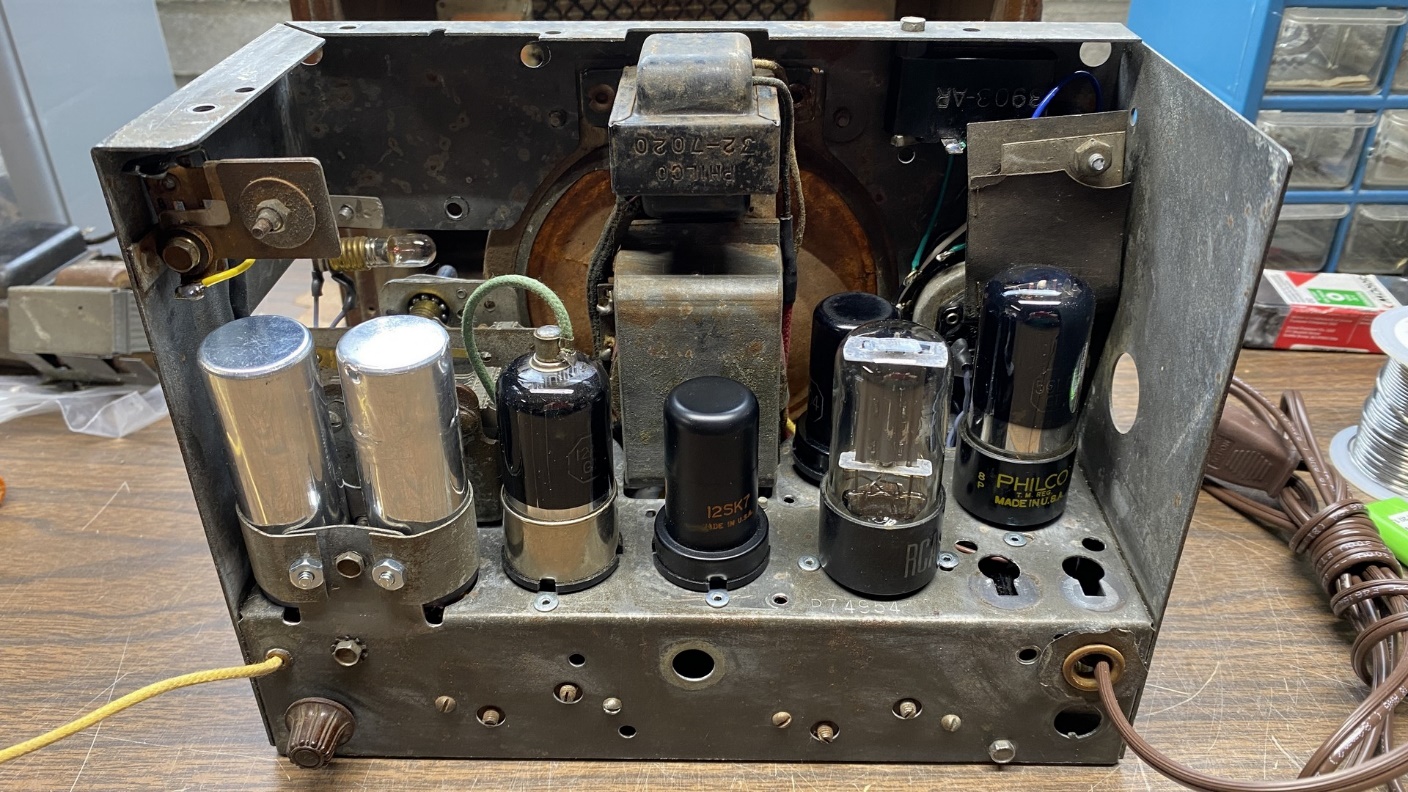
The 54C chassis with a complete set of tubes installed.
In case you were wondering, yes, I did use a polarized power plug so the “hot” lead is always connected to the radio’s power switch and the “neutral” lead is always connected to the radio’s B- line.
For those of you who do not know this, the wide blade of the plug is supposed to be connected to the neutral side of the AC line.
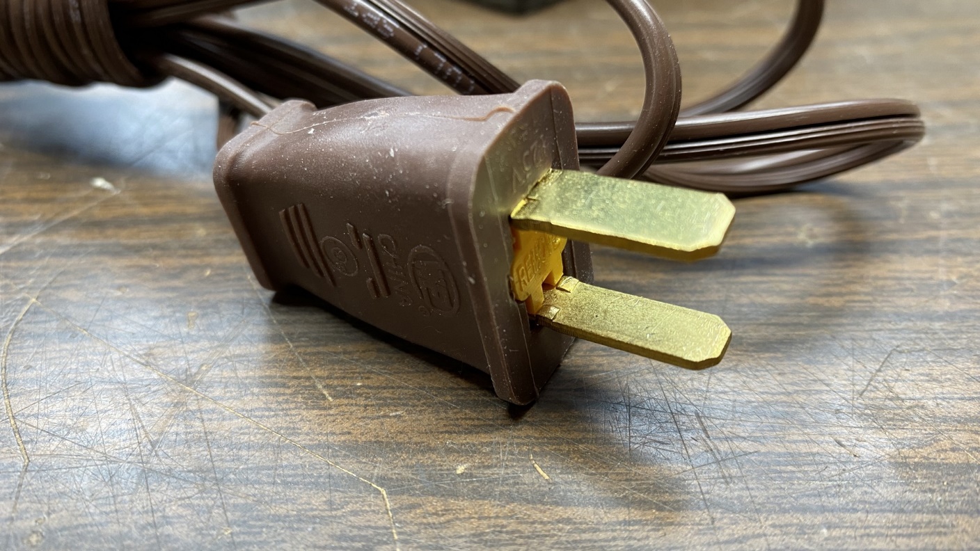
A polarized AC plug is connected to the end of the AC cord.
I plugged the radio in, connected the longwire antenna to the radio’s antenna lead, and turned it on.
The radio did come on, but performance seemed sluggish. I took some voltage readings, and found that B+ in the radio was only around 50 volts or so, a far cry from the 90-100 volts I expected to measure.
And then I realized my error. I had retained the original speaker, and it uses a 2600 ohm field coil connected between unfiltered B+ and B-. That field coil alone draws 40 milliamps (mA) of current. The 35Z5 rectifier tube is only capable of producing 70 mA of current. So, the field coil was pulling the total B+ voltage down.
Lesson learned: always be certain of total B+ current draw before choosing a particular rectifier tube for a purpose.
I would need to convert the radio to use a permanent magnet (PM) speaker in order to make this project successful. Therefore, I removed the original speaker. I looked through my parts stash and I did not have a 5-1/4” pincushion speaker. These speakers were once very common in many of the better 1950s AA5 radios (most AA5s used a square 4 inch speaker), but are difficult to find now.
I posted ads looking for a 5-1/4” speaker. I soon learned that many collectors did not know what a pincushion speaker was, which frankly amazed me. Such speakers were commonly listed in parts catalogs issued by many of the older radio supply companies, such as Allied, Burstein-Applebee, McGee Radio, Olson, and others years ago before most of them went out of business (Allied Electronics remains in business today).
The photo below shows a picture of an eight inch pincushion speaker.
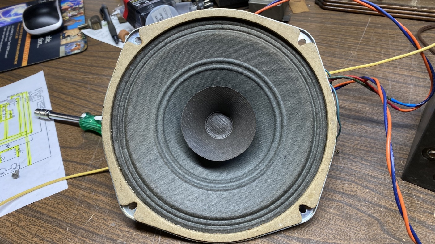
This eight inch pincushion speaker was used temporarily with the 54C for testing purposes.
Notice how the frame is not perfectly round but is wider at the mounting holes. This design characteristic is what led them to be named “pincushion” speakers.
Not having a replacement PM speaker of the proper size, I used the speaker pictured above as a temporary test speaker. This also meant that I would need an audio output transformer.
Fortunately, I just happened to have a new-old-stock transformer on hand.
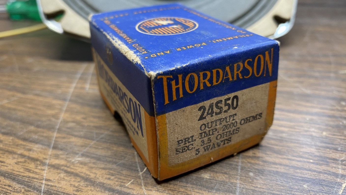
A new-old-stock Thordarson audio output transformer.
The 50L6GT has an output load impedance of 2500 ohms. The 2000 ohm primary of this transformer was suitable for this application.
I temporarily bolted the transformer to the test speaker and ran long wires from the transformer primary into the 54C chassis as shown below.
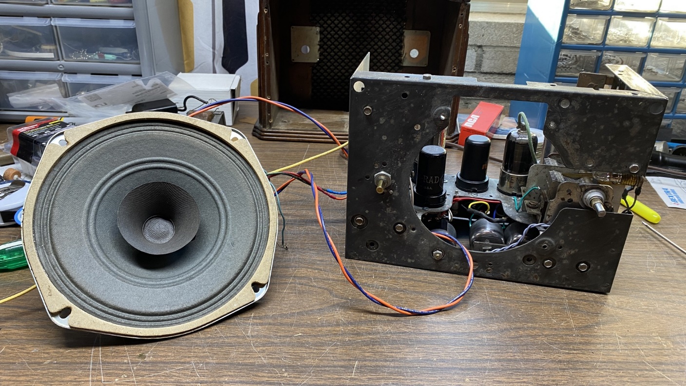
I prepare to try out the 54C with the test speaker.
Before I tried the radio out again, I felt I should test that 35Z5GT since it had been put under a strain from too much current running through it. I found that it now had a heater-to-cathode short. I tossed it into the trash can and installed another 35Z5GT, testing it first to make sure it was good.
With these changes made, I tried the radio out again.
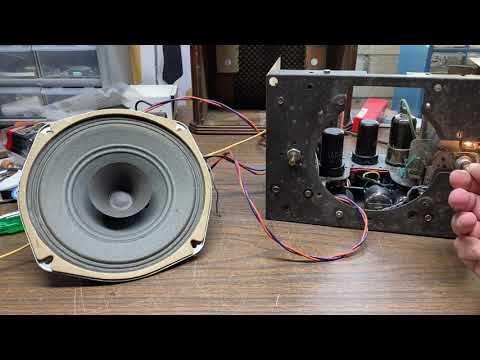
As you can tell from the video above, the radio was now working. I took voltage readings again, and they were now as they should be. However, while the radio was indeed working, it was not working correctly. We have a local AM station operating at 990 kc (kHz); it was not coming in at all. It seemed that stations normally on the high end of the AM band were coming in in the middle or towards the lower end of the band.
Ah, another problem! Next time, I will attempt to resolve that problem. Please come back for the final chapter of this series.