In our last exciting (?) installment, I had discovered that switch wafer D had developed a bent contact. Yes, I did try to straighten it, but I could immediately tell by the feel of it that it was about to break, since the metal used for the switch wafers is very thin. Replacement was indicated. To replace the wafer would require two things: one, another 37-116 RF unit from which to take a switch wafer “D”; and two, totally disassembling the first RF or converter section down to the point of separating the wafers and then doing the same with the other 37-116 RF unit.
And then I remembered something.
About five or so years ago, I had rebuilt a Philco 37-670. In the course of doing so I ended up having to remove its RF unit and install one from another 37-670 chassis which I happened to have on hand. I still had the separated antenna, RF/converter, and oscillator sections.
So, I did some research to see if the RF/converter section from a 37-670 would work with a 37-116 RF unit. My research determined that it would indeed work. I further determined that it would be easier to simply rebuild the 37-670 RF/converter section rather than tearing down both, switching (no pun intended) wafers around, and reassembling one.
Here are the five RF coils from the 37-670:
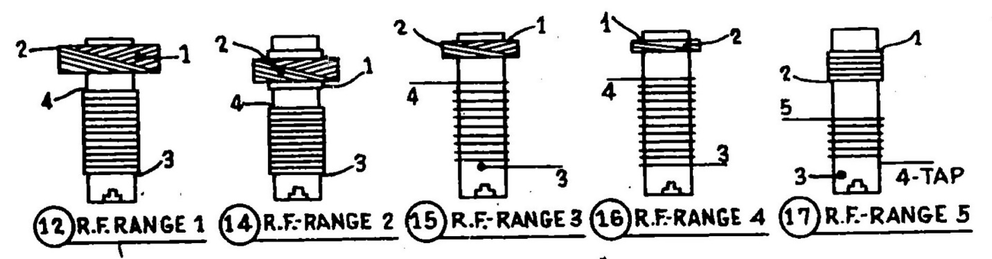
The coils used in the 37-670 RF/converter section.
I needed to draw yet another wiring diagram or “road map” before I started disassembling this section, so I would know how to rewire everything but the coils. I would use the coil drawings above in addition to the 37-670 schematic to put the coils back into place.
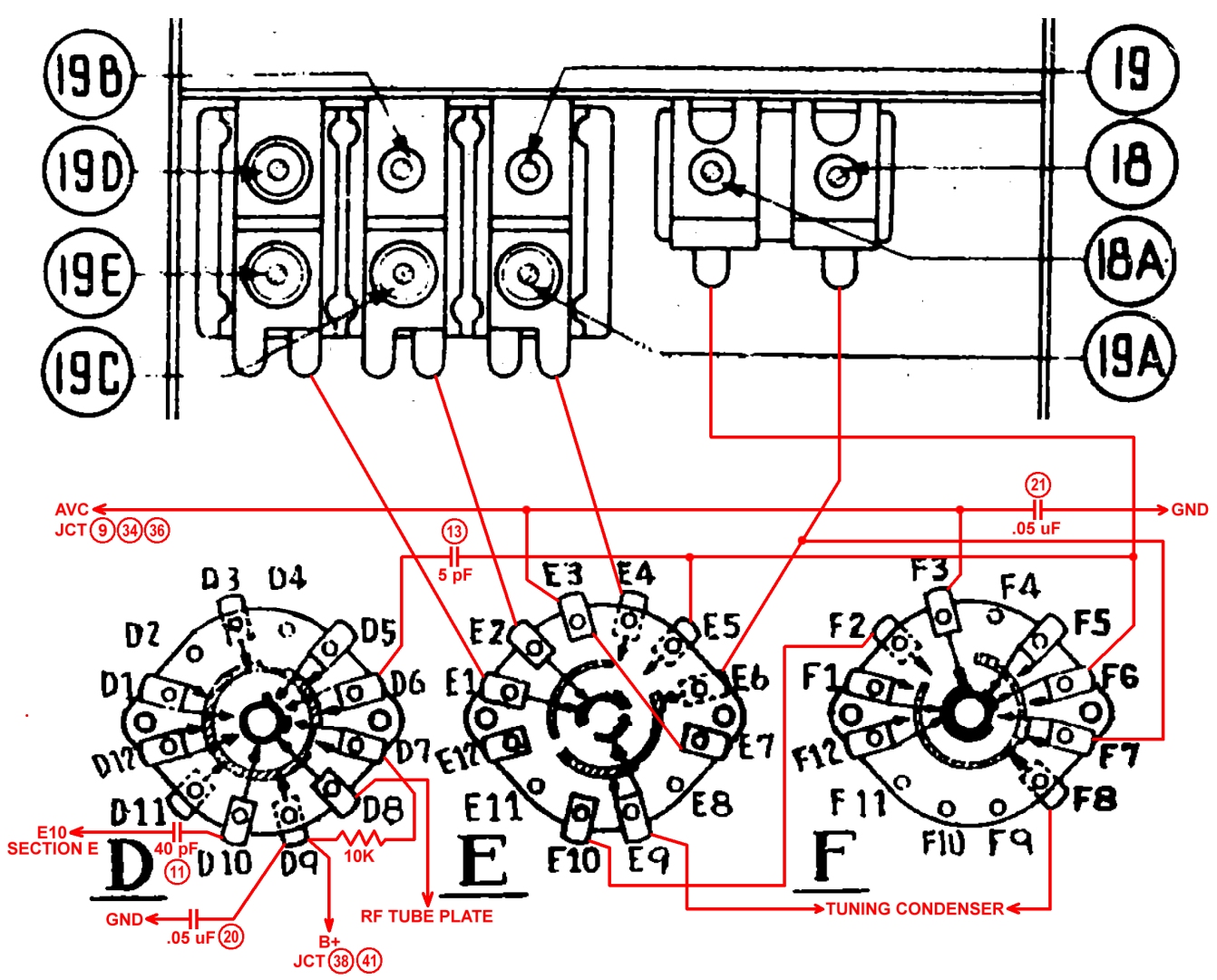
Wiring diagram for the 37-670 RF/converter section.
Now, having made my wiring diagram, I proceeded to disassemble this section. First the switch assembly with coils attached was removed from the trimmer condenser assembly, then carefully, one by one, each of the five coils were removed. Due to the way these coils were wired into the switch assembly, I found it easiest to first remove the Band 3 RF coil, and then proceed to remove the others. Once this was done, any remaining wires, a resistor, and two mica capacitors were also removed.
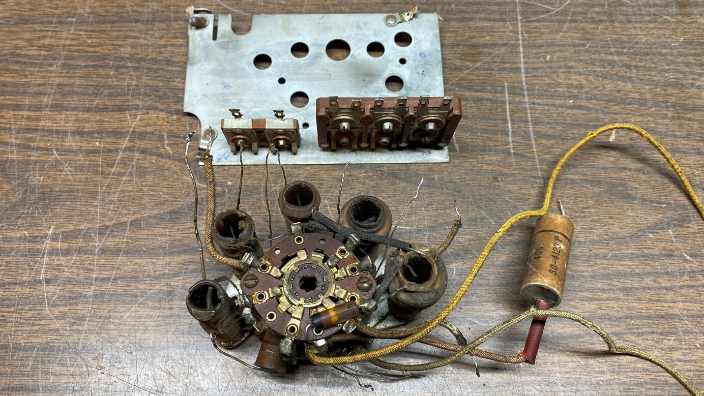
The 37-670 RF/converter coil & switch assembly, removed from its trimmer condenser assembly.
Eventually, I was left with the bare switch assembly as shown below.
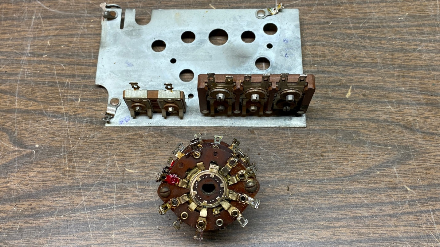
After removal of the five coils, all wiring and components.
The next thing to do was to separate the three wafers of the switch assembly so that they could be cleaned with 99% isopropyl alcohol.
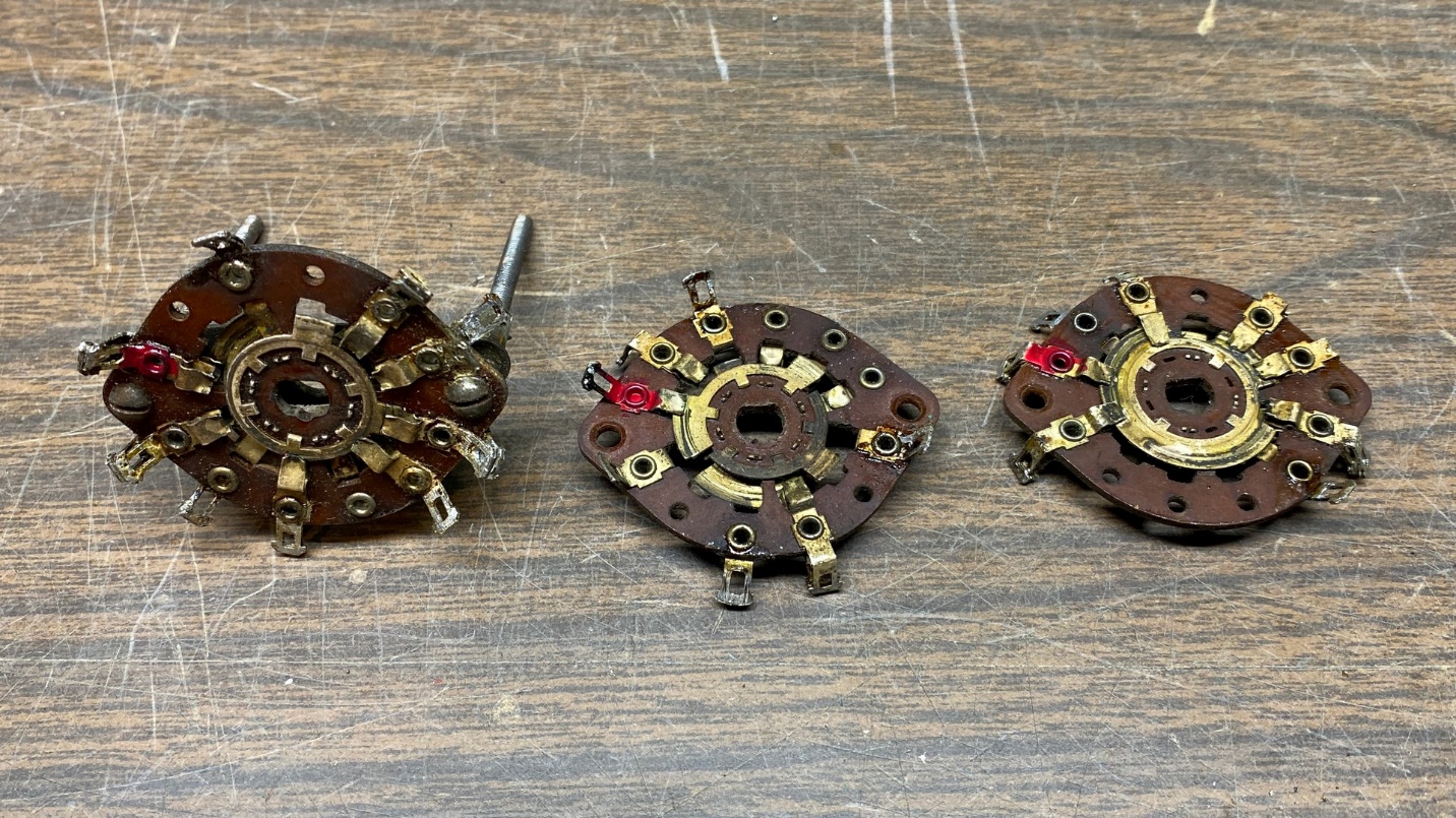
The three switch wafers, disassembled and ready for cleaning.
Notice in the photo above how dirty the switch wafers were. Compare that to the photo below, after the wafers were cleaned:
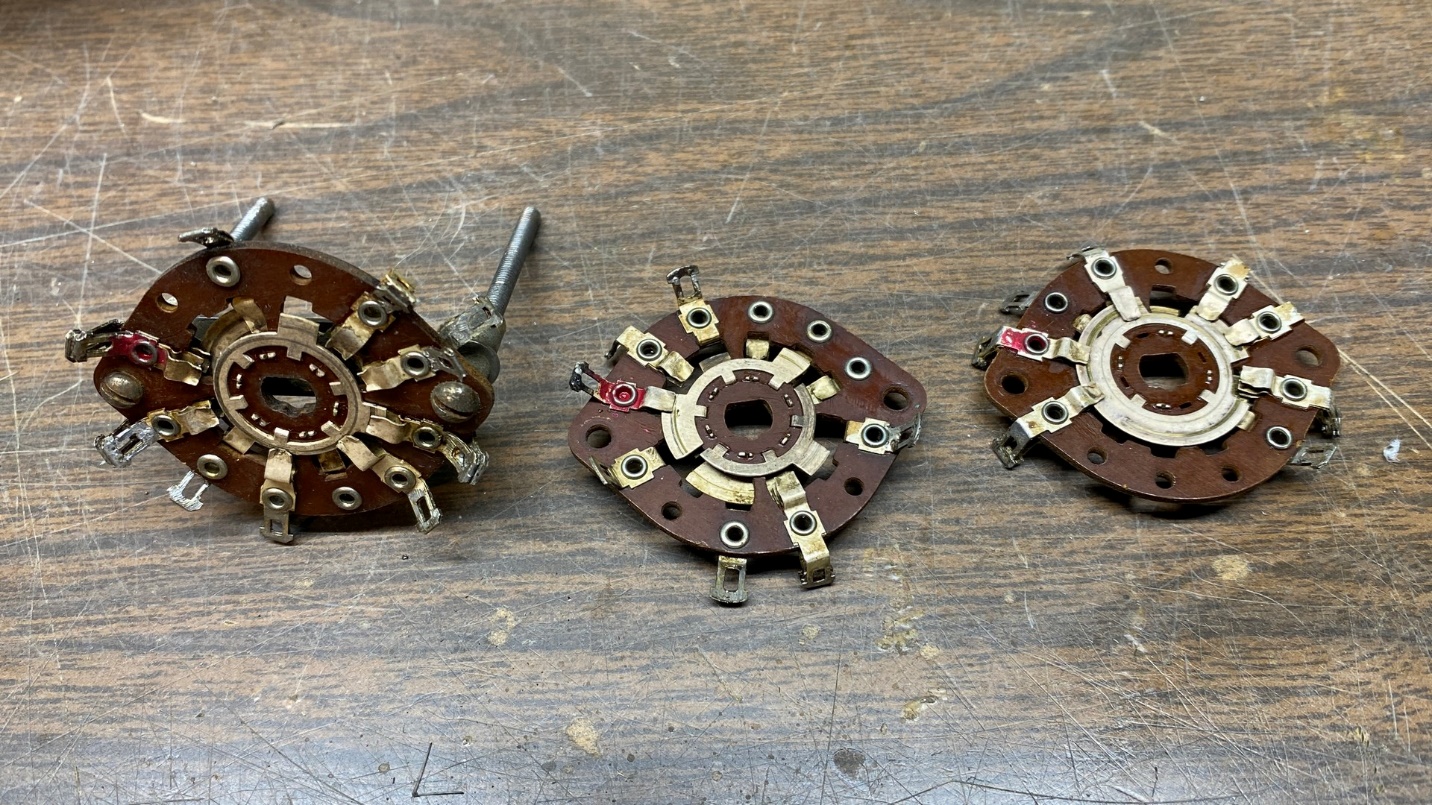
The three switch wafers after cleaning with 99% isopropyl alcohol.
No carbon tracks were seen on any of the switch wafers.
Next came reassembly of the switch wafers back into a single triple-section assembly.
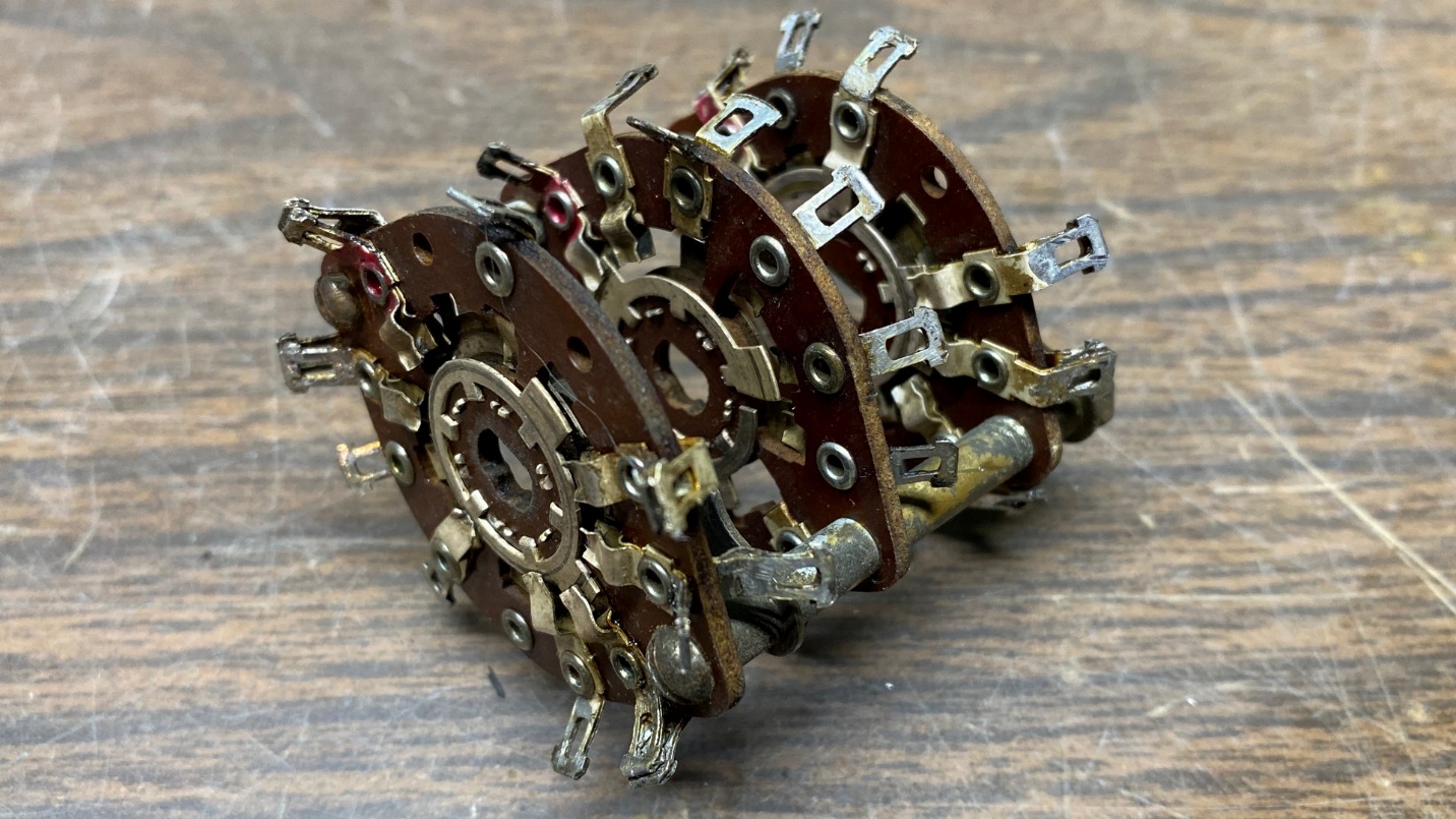
The switch assembly is now reassembled.
And after the switch wafers were reassembled, the assembly was bolted back onto the plate which holds the five coils.
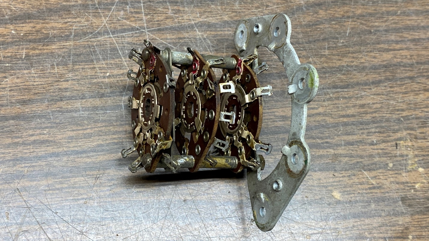
Switch assembly reattached to the plate to which the five coils will be mounted.
I baked all five coils in my old toaster oven for 30 minutes at 225 degrees Fahrenheit. After baking and allowing them to cool, I checked all five for continuity. All tested good. One wire broke off the Band 4 RF coil; fortunately, it was easy to repair by adding a long length of newer wire to the point where the old wire broke off.
The five coils, after baking. They are now ready to be reattached to the switch assembly.
Before I began to reinstall the coils, I attached the wires to the switch assembly which would be routed to the trimmer condenser assembly along with a long white wire which will be going into the main section of the radio chassis, and one of the new .047 uF capacitors to replace the .05 uF capacitor which was tucked between switch wafers.
Then, one by one, I reattached each coil to the plate to which they are mounted, and attached each of the fine coil -wires to the proper switch terminals. I saved the Band 3 RF coil for last to ensure other wires could be soldered where they needed to be. During reassembly, I also added a new 5 pF mica capacitor to replace the old one which had been removed.
Everything is now reassembled. This section is ready to become part of the 37-116 RF unit.
I attached this assembly back to the trimmer condenser assembly and then proceeded to attach the remaining wires and components, double-checking my work against my wiring diagram and the 37-670 schematic as I went along.
Finally, the reassembly was complete. Next time, I will install this into the 37-116 RF unit, reattach the antenna section to the same unit, and carefully install the switch shaft. I will make sure the switch changes smoothly and that no more contacts get bent. Then, it will be ready for testing.
Until next time!