There are not a lot of parts to replace in a Philco model 87 radio. Several capacitors – three of which are encased in three tubes (the precursor to Philco Bakelite block condensers), and eight in the large multi-section filter condenser can.
If you want to follow along, you can find service information for Model 87 HERE and HERE.
We will deal with the multi-section filter condenser can later. Right now, let’s start with the easiest parts – the capacitors and resistors in the small modules, or tubes, under the chassis.
As you may recall from Part 1, this radio was missing one of the modules. I found something suitable in my parts bin. The replacement I found is black and is part number 3292-B instead of 3292-A, close enough.
Not only do these modules have a 0.1 uF capacitor inside – they also have a hank of resistance wire. 100 ohms’ worth to be exact.
In my haste, I forgot to take any “before” photos of the capacitor/resistor modules. Like the Bakelite blocks, these have their components encased in a black waxy substance.
I pulled out my old toaster oven, which I use only for heating up old paper capacitors, and cooked all three modules for 30 minutes at 225 degrees F. This allowed me to remove the old components from the tubes.
I then prepared three sets of 0.1 uF, 630 WVDC capacitors and 100 ohm, 1 watt resistors. For each module, I inserted a capacitor/resistor set.
As you can see below, each end of each capacitor has one lead of the 100 ohm resistor soldered to it. On the other end, the two leads are separate. This is important. The separate lead of the capacitor is soldered to the mounting lug of the module, while the separate lead of the resistor is soldered to the solder lug above the mounting tab on the same end of the module. The combined lead of both components, on the other side of each, is soldered to the solder lug on the other end of the module.
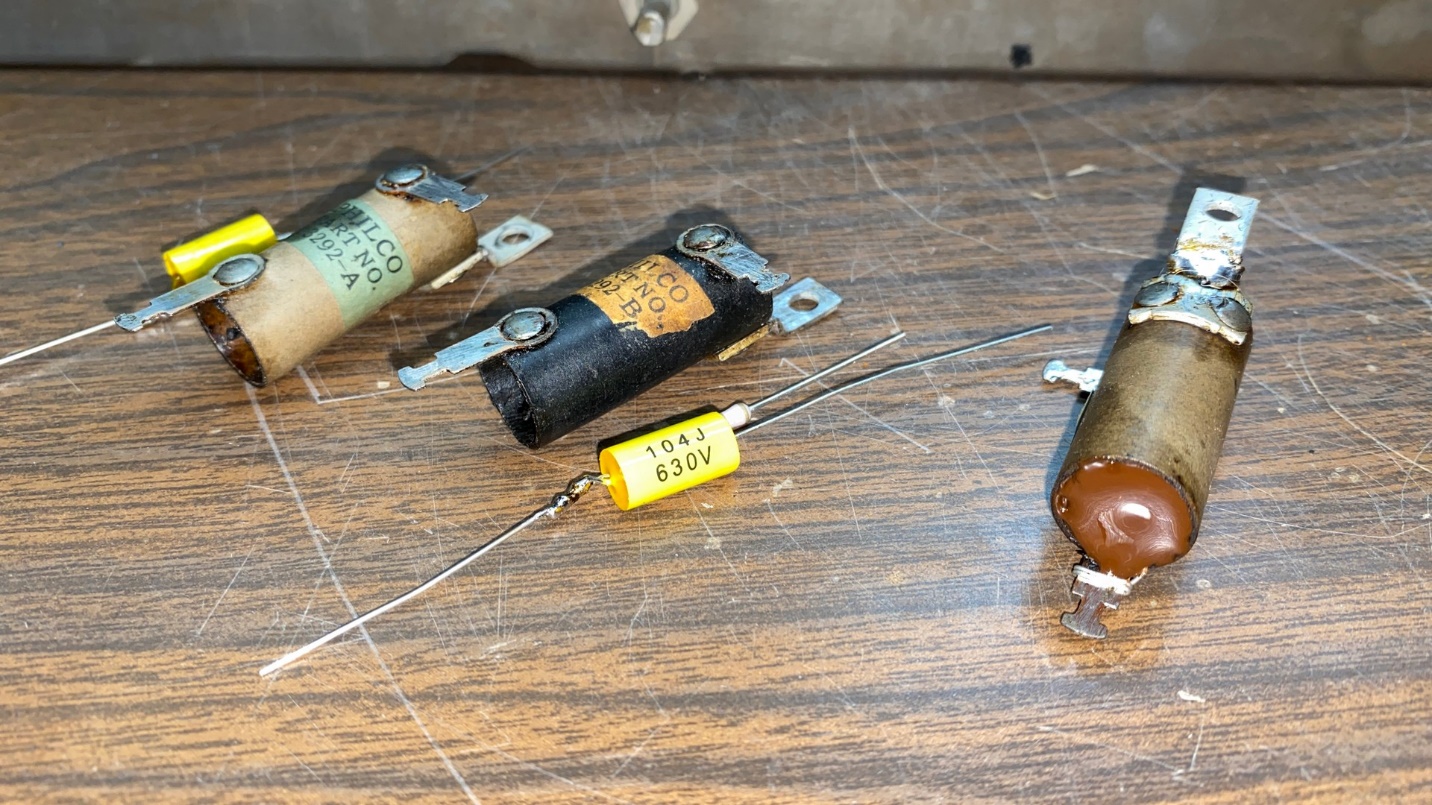
Three Philco capacitor/resistor modules. Two are empty and ready for new components; the one on right has been rebuilt.
Once the leads are soldered in place, the module is filled with brown hot glue to approximate the original look of the filled module.
Lather, rinse, repeat for the other modules.
Once done and the hot glue has cooled, these components may be reinstalled under the chassis.
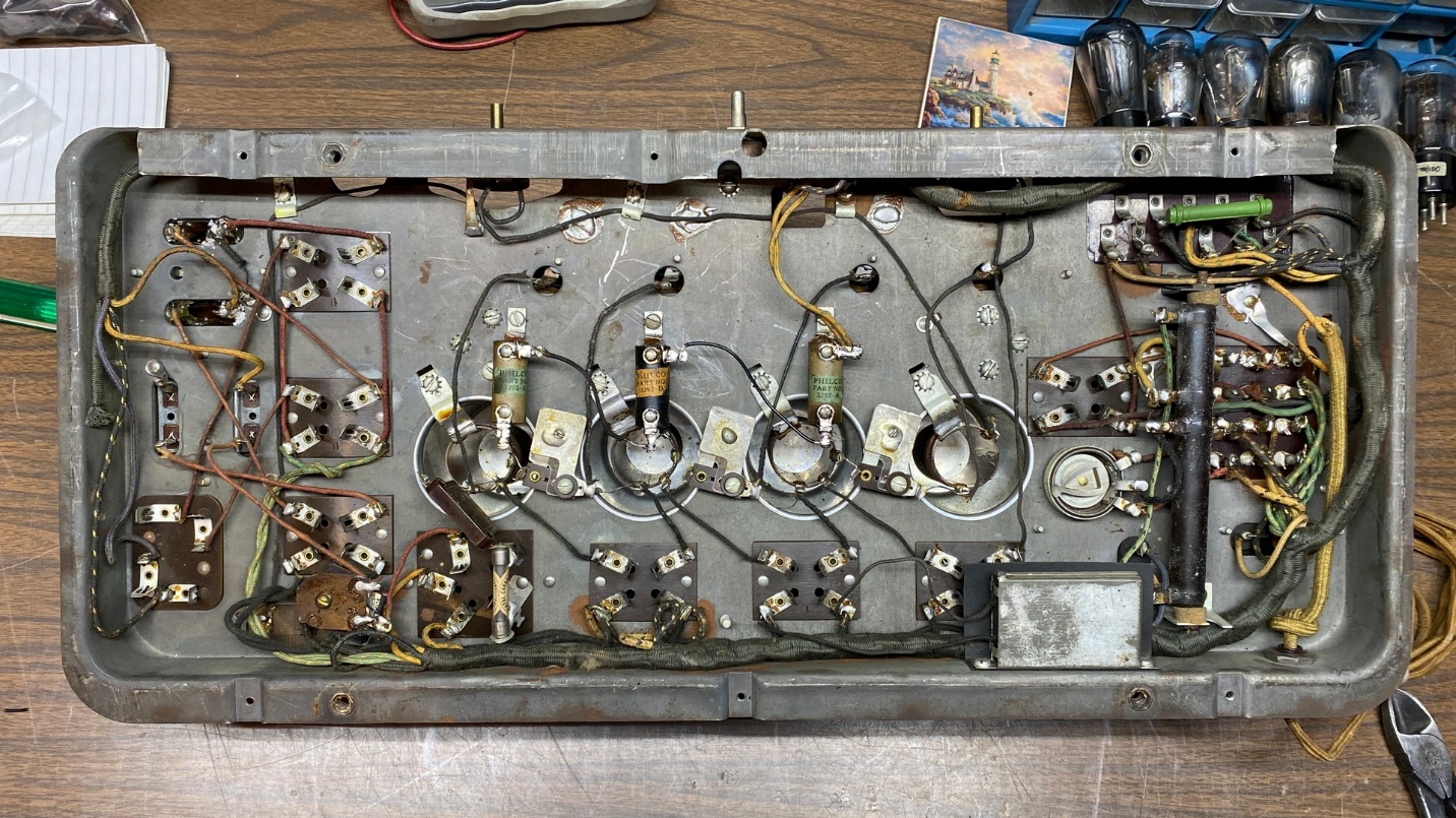
The rebuilt modules have now been reinstalled under the chassis and look original.
This allows new components to be used while preserving the factory original appearance.
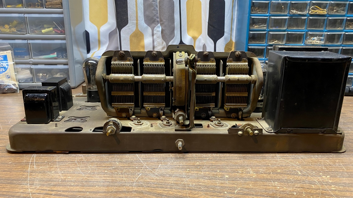
This is all I am going to do today. Next time, I will tackle that big filter condenser can which is mounted above the chassis, next to the radio’s power transformer.