Taking care of minor issues.
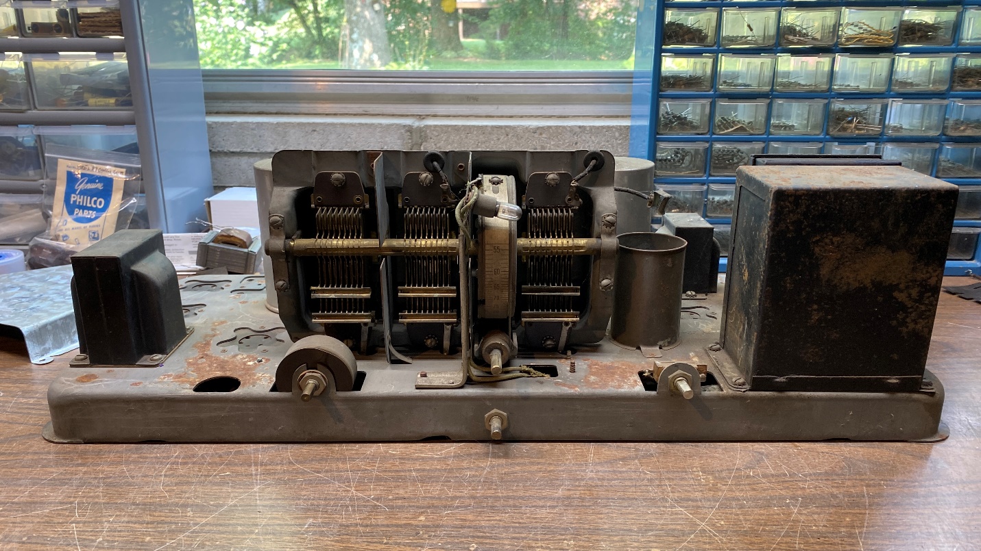
Having repaired the major problems in this Philco model 65, it was now time to start addressing the multiple minor things which needed to be taken care of.
The Volume Control, part (25)
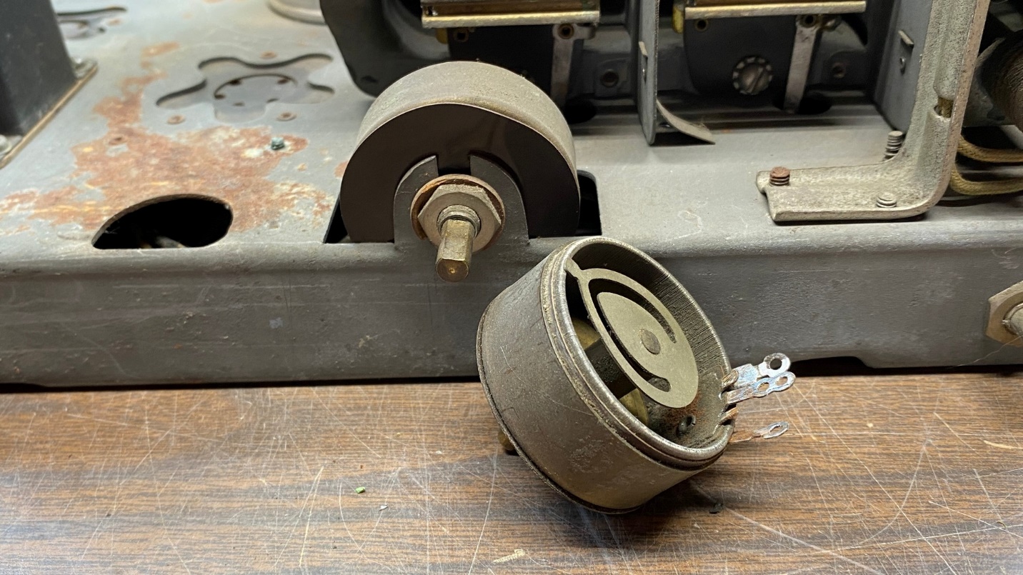
The original model 65 volume control, bolted in place, and its replacement which had come from a junked model 65 receiver.
You may recall from Part 1 of this series that the radio’s volume control was open. Through a stroke of good luck, I just happened to find another model 65 wirewound volume control in my parts bin. I checked it with my digital multimeter – and it was ok!
So, I prepared to install it in this model 65, in place of the open control.
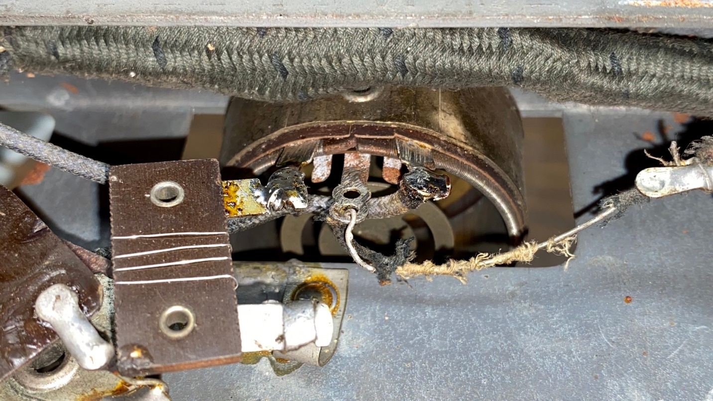
Connecting the wires to the replacement control.
Once the control was bolted in place and two of its three wires were connected underneath the chassis, the replacement control was ready for service. It looks like the original, and for good reason – it is an original 1750 ohm wirewound control from another model 65 set.
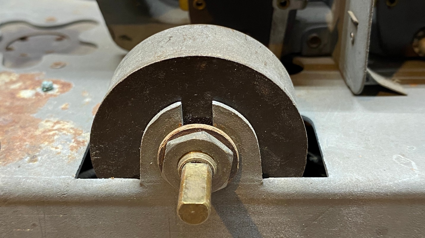
The replacement volume control is now in place.
0.5 uF capacitor, part (13), and 32,000 ohm resistor, part (14)
This radio uses a single 0.5 uF capacitor in the detector circuit. The capacitor is enclosed in a metal container.
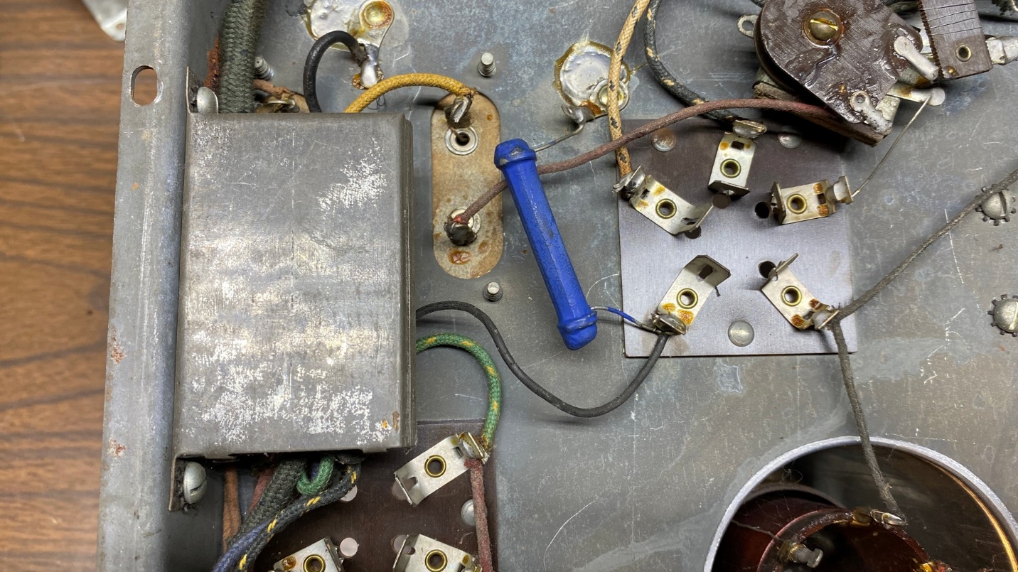
0.5 uF capacitor (13) at left. Also notice the blue resistor, part (14).
If you have worked on early Philcos such as models 90, 111, 112, etc., you are familiar with these long rectangular capacitor cans which can hold one or two capacitors. They are easy to rebuild with new components.
The first thing I did was to remove the capacitor can from the side of the chassis by removing the two screws which held it in place.
Next, I opened the can where the black wire goes in and unfolded the four tabs which held everything in place. The black fiber insulator should be moved out of the way. I then pushed everything out from the back of the can, using a small screwdriver.

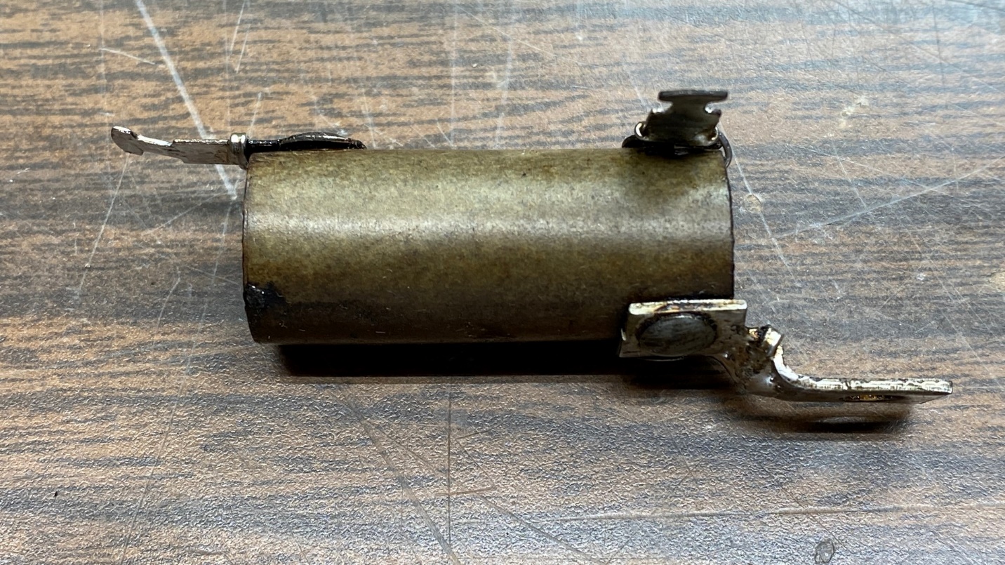
The disassembled capacitor (13) now lying on the bottom of the chassis.
There was a thin bare wire soldered to the rectangular can. The other end of that wire was fastened to the capacitor, which was covered in a black tar-like substance. I carefully pulled that wire off the capacitor and unsoldered the wire from the solder tab which comes off with the wire when it is pulled from the end of the capacitor.
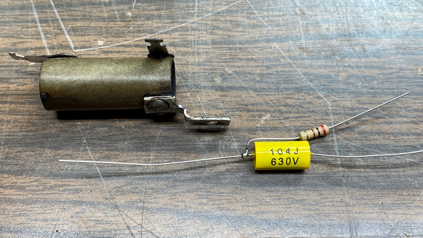
Next, I pulled a new 0.47 uF, 630V capacitor from my parts drawer. I soldered the thin bare wire to one end of the new capacitor. On the other end, I soldered a new black wire since the old one had crumbling rubber insulation.
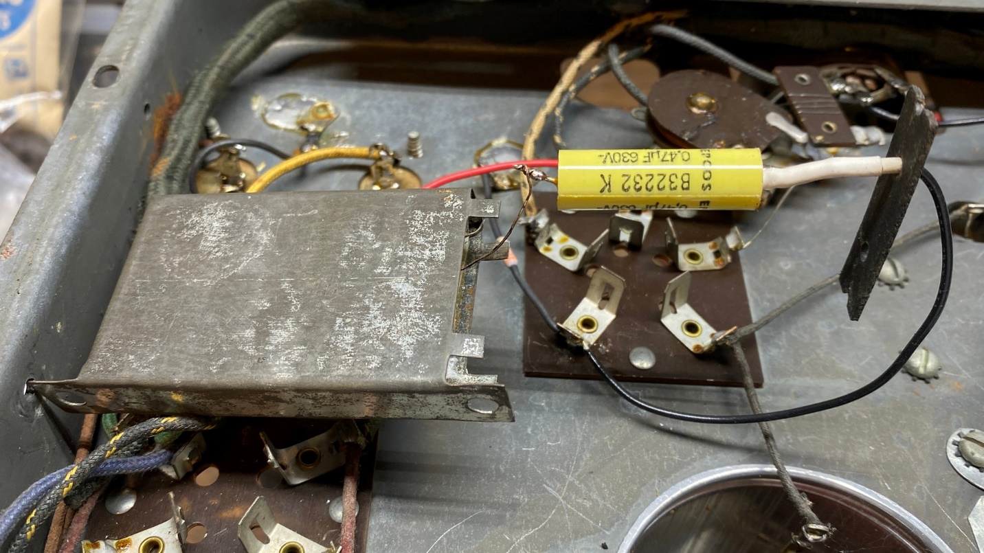
A new 0.47 uF capacitor is ready to be stuffed into the old can.
I pushed the new capacitor, along with the thin bare wire, back into the can. The end with the thin bare wire goes in first. It is not necessary to fill the can with wax or hot glue, although you may do so if you wish. Next, I added a piece of heat shrink tubing to cover the area where I soldered the new black wire to the new capacitor. Slide the new black wire through one of the holes in the black fiber insulator and put it back into place, folding the four tabs of the can back over to hold everything in place.
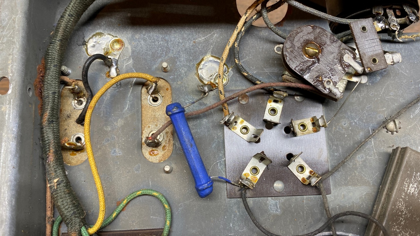
The blue resistor, part (14).
Before I bolted the restuffed capacitor (13) temporarily back into place, I decided to go ahead and replace resistor (14), 32,000 ohms, 1 watt. The replacement resistor is 33,000 ohms since 32K is no longer a standard value. It is also rated at 1 watt. You can see it in place below.
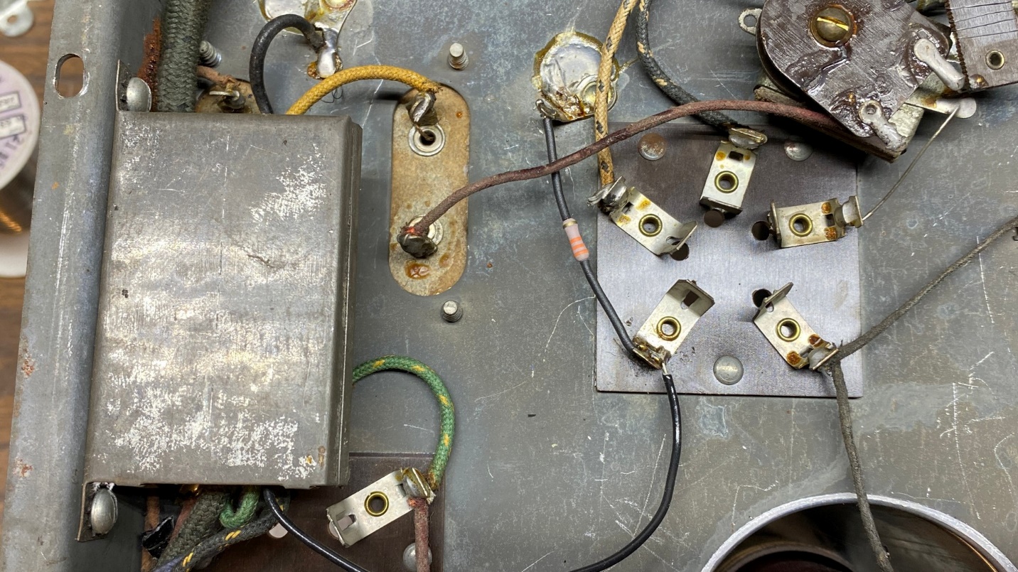
Restuffed capacitor (13) temporarily back in place. Resistor (14) has been replaced.
Why did I say I reinstalled part (13) “temporarily”? Simply because I have found that the primary of audio interstage transformer (17) has an open primary. I will deal with that later. Before I do that, however, I want to restuff those tubular capacitor modules.
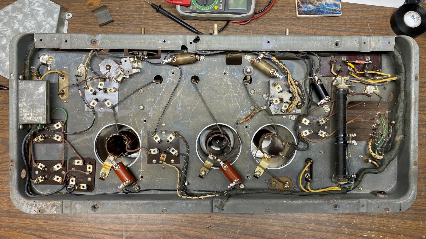
Tubular Capacitors – Parts (5), (6), (9), (10), (27)
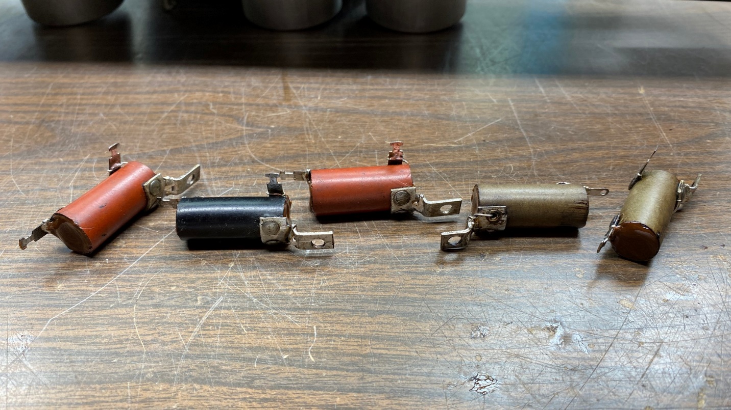
There are five small tubular capacitors used in the model 65. Four of them include a capacitor and a resistor; one only has a single capacitor inside. You can see them scattered around the chassis in the photo below.
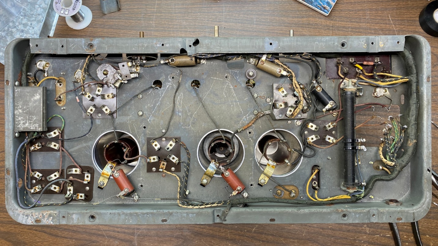
Five tubular capacitors are used in the model 65 and are shown above. Two are tan, two are red, and one is black.
I unsoldered the leads from each one and removed all five from the chassis.
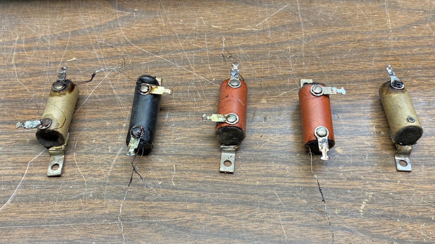
The five capacitors after removal from the radio.
I then brought out my toaster oven, which I use for cooking capacitors, coils, and other components. I placed the five capacitors on the tray of the toaster oven, which is covered in aluminum foil. I set the temperature to 250 degrees, closed the door, and turned the unit on.
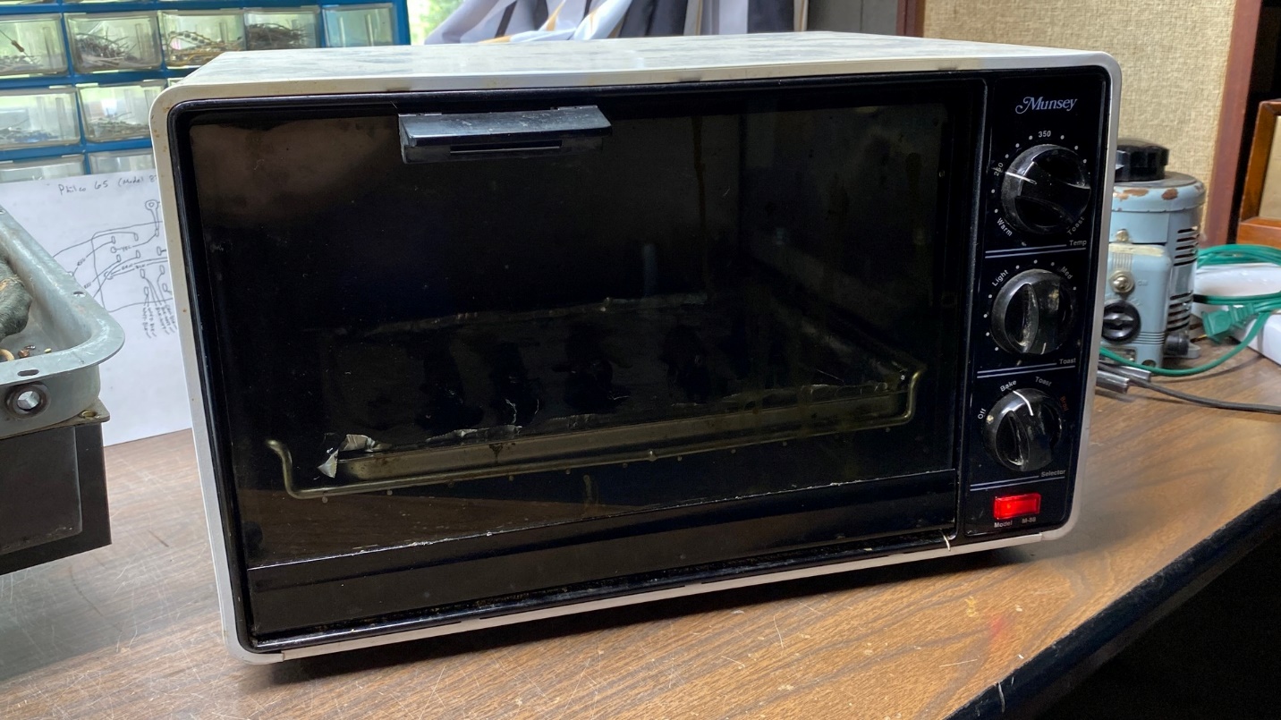
The five capacitors are now cooking in the toaster oven to soften the waxy substance so that the insides of each may be removed.
After 20 minutes, the capacitors were ready to come out and have their insides removed.
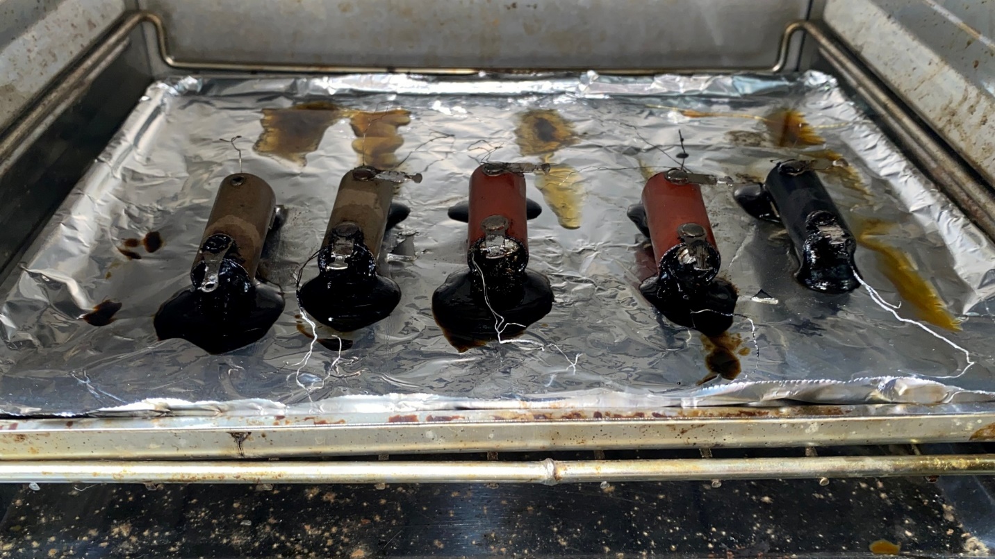
Cooked capacitors. Yum.
One by one, I removed each tubular capacitor and pulled out the insides of each one. I also tried to get out as much of the tarry substance as possible, to ensure there would be plenty of room inside each for the new components.
Capacitor (9) with its original component removed.
The next few pictures tell the story of how I handled these old capacitor modules.
A new 0.1 uF capacitor is ready to go into the shell of part (9).
The restuffed component. One end of the new capacitor is connected to the mounting lug; the other to the terminal on the other end.
End view showing the new capacitor inside the old shell. Once filled with hot glue, the old component will look much as it did originally.
Now let’s look at part (5). This uses a 0.1 uF capacitor and a 200 ohm resistor. You can see the combination above. The common end of the resistor and capacitor connect to the terminal lug on the left of the old component. The free end of the capacitor connects to the mounting lug at right. The free end of the resistor connects to the remaining terminal lug above the mounting lug.
Part (5) is now restuffed and ready for the finishing touch – hot glue.
All five capacitors have now been restuffed and are ready for reinstallation into the radio.
While doing this work, I discovered there is an error on the Model 65 schematic. Part (6) is listed as 0.1 uF with a 200 ohm resistor. It is actually 0.05 uF with a 200 ohm resistor.
½ watt resistors are sufficient as replacements for the old resistance wire found inside the old capacitor modules.
After all five have been restuffed, it is a simple matter of reinstalling them into the radio chassis.
I had taken a photograph of the underside of the chassis prior to starting this job, so I knew which capacitor went where.
The restuffed capacitors have been reinstalled and retain their original appearance.
Well, I have done a lot of work this time around. More remains to be done, including addressing that audio interstage transformer, replacing and repairing some wires which had been chewed by the mice, and reinstalling the power transformer. I will get to all that in the next installment of this series.