Applying the final touches.
Now that I was committed to turning my Philco model 87 radio into a sort-of model 83, it was time to replace those three rubber-covered wires used in the 83 power transformer, paint the transformer, and install it into the 87 chassis. I also needed to take care of a few other things, such as adding a power cord and plug and a dial lamp. I would also have to do some more grinding on power resistor (35). Although I mentioned this in the last installment of this series, I will show you what I intend to do with this power resistor later in this posting.
Let us begin with the model 83 power transformer.
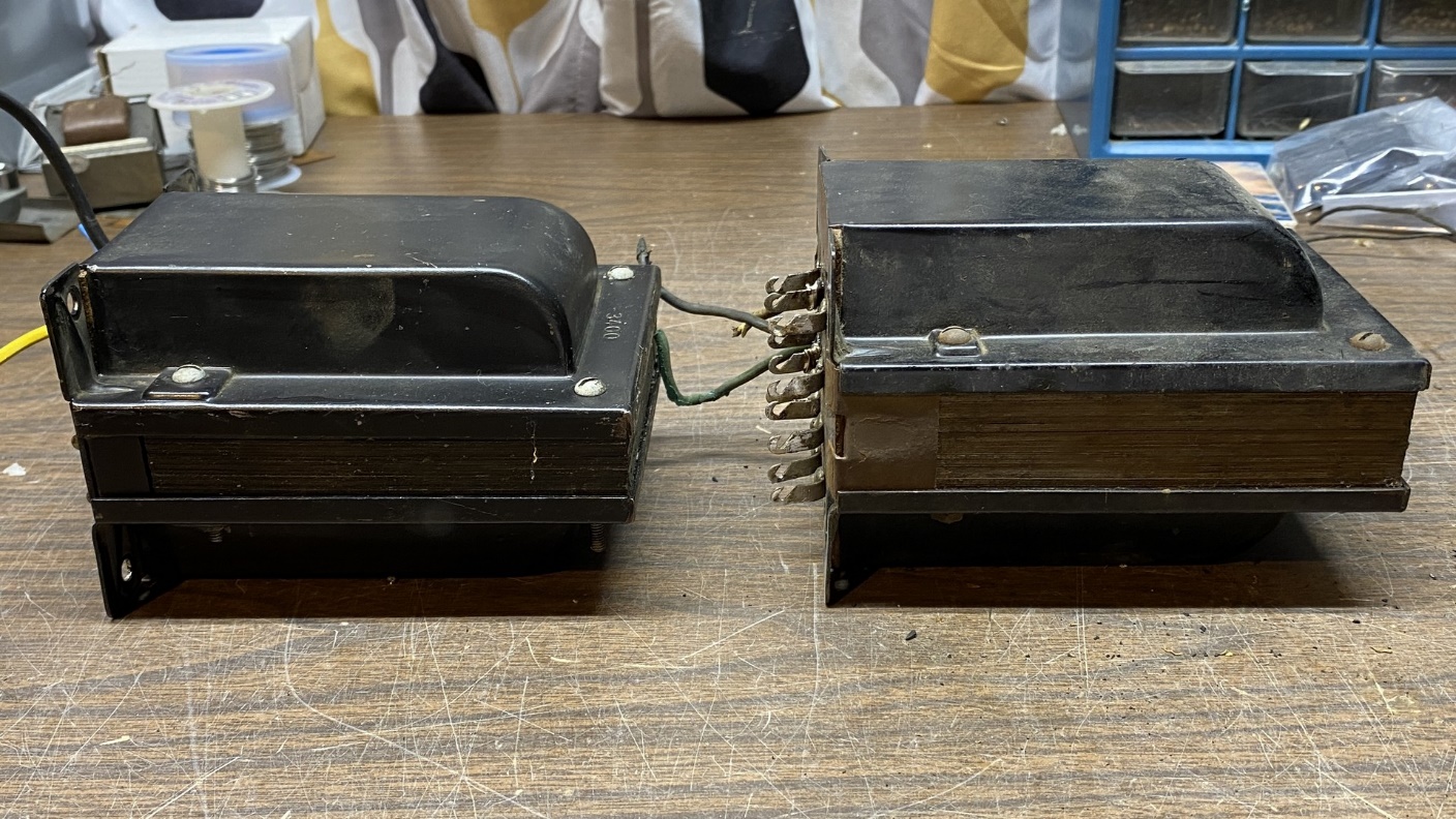
Model 87 power transformer (left) and model 83 power transformer (right). Notice that the 83 transformer’s laminations (center section of transformer) are thicker since it was designed to operate on 25 cycle AC. 25 cycle power transformers are always thicker and heavier than 60 cycle power transformers.
I opened up both the 83 power transformer and the bad 87 power transformer. I unsoldered two of the three wires I had attached to the 87 transformer which had been intended to replace rubber-covered wires. I would need a longer yellow wire due to where it needed to connect inside the 83 transformer. I made a new one from one wire of AC zip cord, which I then covered with yellow heat shrink tubing.
I ended up getting so involved in preparing the 83 transformer for use that I did not take any “in process” photos. I checked the other wires inside the transformer and their 92 year old “spaghetti” insulation was still good, so these were left alone.
Once I had replaced the yellow, green and black rubber-covered wires, I reassembled the transformer and then masked off the bottom side where the terminal board is located. I then proceeded to paint the transformer with two coats of Krylon Satin Black spray paint.
You can see the results below.
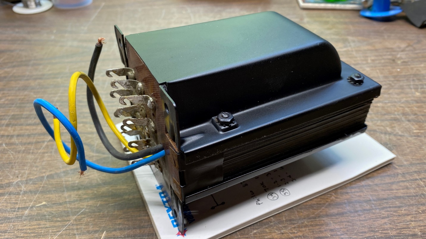
A freshly painted power transformer.
Now it was time to bring the 87 chassis out of storage so I could install the 83 power transformer.
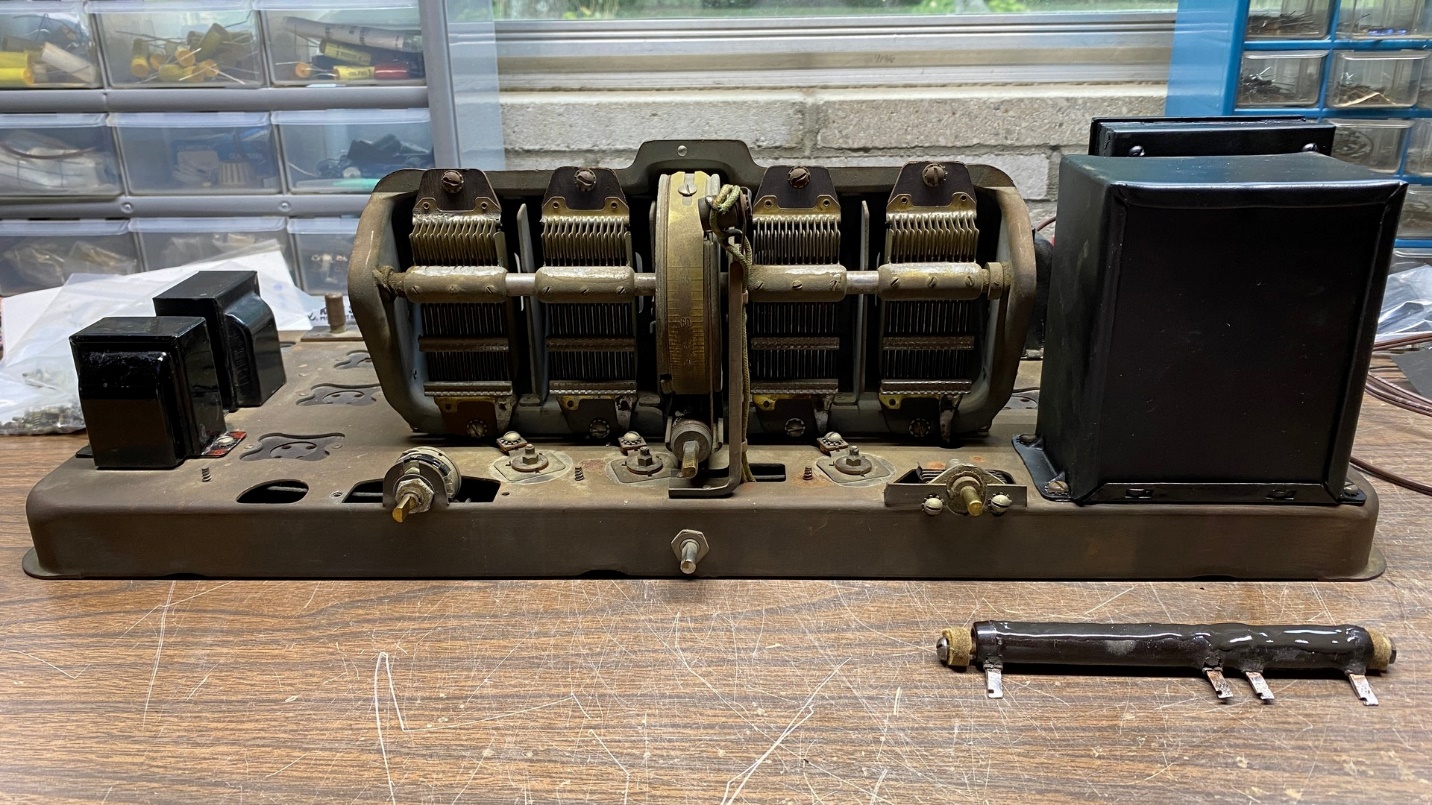
Philco 87 chassis sans power transformer. The 83 transformer will be installed where the hole at left is located.
While I did not expect any issues installing the 83 transformer onto the 87 chassis, I did a test fitting to make sure the mounting holes would line up properly on the chassis.
They lined up perfectly, so I removed the tubes and then installed the two metal screws on one side of the transformer and the two screws and nuts on the other side.
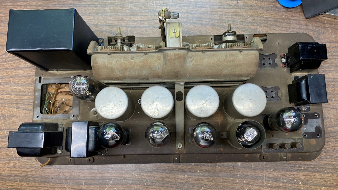
Model 83 power transformer in place on the 87 chassis.
The two screws and nuts mount that side of the transformer to slotted holes, so either the 87 or 83 power transformer physically fit this chassis.
Now that the transformer was securely mounted to the chassis, it was time to connect all the wires to the proper terminals.
As you will see in the two photos below, I replaced a few of these wires since the old wires looked a bit rough.
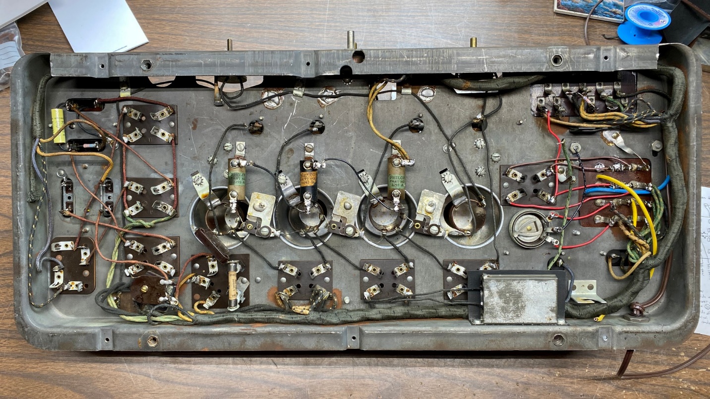
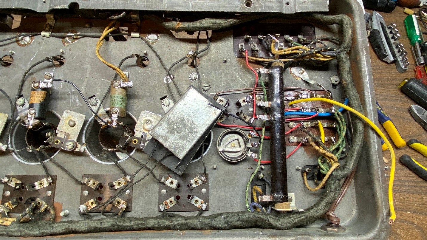
Bottom view of Philco 87 chassis with 83 power transformer wired in place.
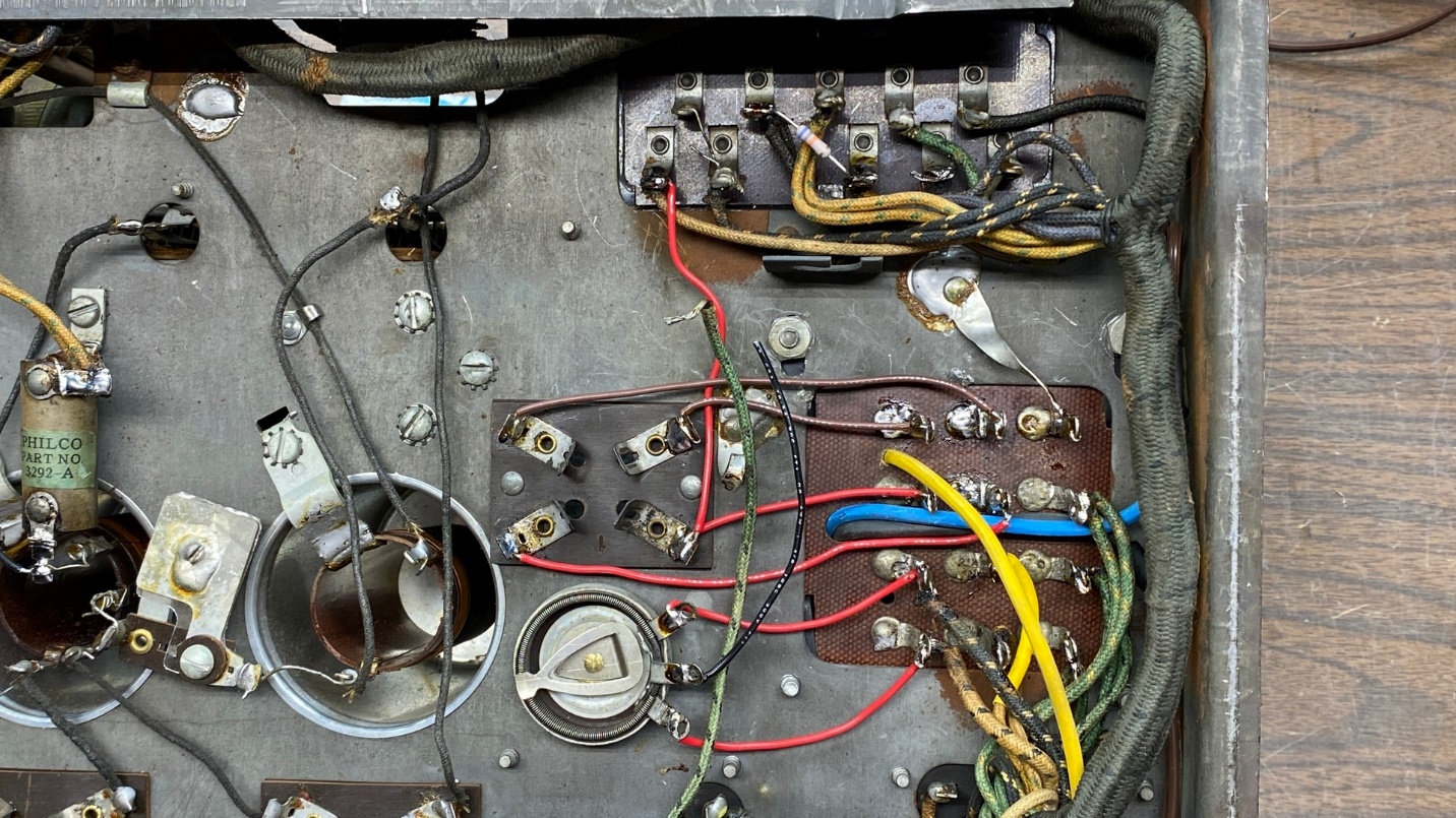
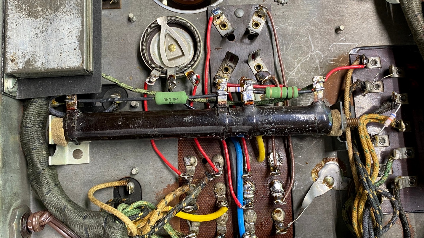
A closer look at the Philco 83 power transformer wiring underneath the Philco 87 chassis.
I went ahead and replaced the AC cord while I was connecting the power transformer wires. This time, unlike with the model 65, I managed to route the AC primary leads in a similar manner to the factory installation.
I found that I was out of cloth-covered AC cord, so I went ahead and used modern brown zip cord. No, it won’t look authentic, but the radio is no longer authentic anyway with the 83 power transformer and the changes that will necessitate.
Speaking of which, using this 83 power transformer means I have to switch the audio output tubes to 71As. And 71As require a 1000 ohm bias resistor instead of a 640 ohm resistor.
This meant that I needed to do some more grinding on power resistor (35).
Using my Ryobi “Dremel” tool, I went ahead and ground off a portion of the 157 ohm section as well as the 640 ohm section. I did this (a) since the 3785 ohm section was already bad, it was uncertain if the 157 ohm section would remain good; and (b) because I have replacement resistors for each section on hand.
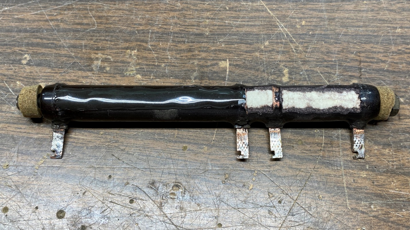
Power resistor (35) with all sections ground off, so that the entire resistor is “open”.
After doing the necessary grinding of both resistance sections, I checked it with my digital DMM to make sure there was no reading between any of the terminals. As expected, it now reads infinite resistance (open) between every terminal.
I then coated the ground-off sections with J-B Kwik (fast drying version of J-B Weld) to cover the ground-off portions and insulate them so there could be no chance of shorts.
The next day, after the J-B Kwik had dried, I installed what was now a ceramic terminal strip into the radio.
The old power resistor, now completely open, reinstalled in the chassis. The areas coated with J-B Kwik are facing the chassis and cannot be seen from this side.
I then installed three resistors across the terminals – 3900 ohms, 5 watts to replace the 3785 ohm section; 160 ohms, 1 watt to replace the 157 ohm section; and 1000 ohms, 5 watts to replace the 640 ohm section. Remember, I had to increase the value of the 640 ohm section to 1000 ohms to compensate for the use of 71A tubes in place of the original 45s. The resistors and associated wires were then soldered in place.
New resistors installed, but not yet soldered, across the terminals of the old power resistor.
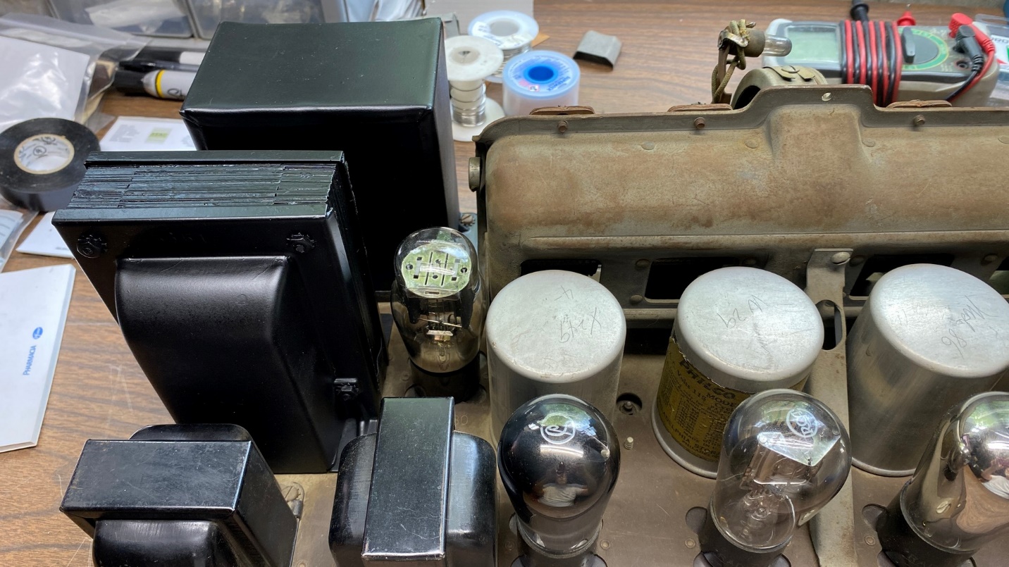
I tested the tubes which came with the radio. The 27 and the 80 were good. All four 26 tubes were weak; two to the point they would be unusable in the radio. I then checked my tube stash and found that I had some globe-shaped 26 tubes and a globe-shaped 27. Two of these 26 tubes turned out to be a little weak also. I picked the strongest four to be installed into the chassis later.
I was very fortunate to have two (and only two) globe-shaped 71A tubes. I also have some globe-shaped 80 tubes, but I did not pull one out right away, deciding to wait until after I had tried the set out.
Now, with no tubes in the radio but with a new screw base LED lamp in the dial lamp socket, I plugged the radio in and turned it on.
No smoke. No sizzling. No KA-BOOM. The dial lamp lit up normally. I took some quick voltage readings, and all seemed well. I then turned the radio off and unplugged it.
Now the radio is ready for me to install the tubes, hook up the speaker and outdoor antenna, and give it a trial run. I will tell you all about that in the next installment of this series. Join me then.