Note: I may post a few articles about radio restorations I have done in the past from time to time as I continue to work on my home improvement project. This is one such restoration, from 2011.
Sometime back in late 2010 or early 2011, I purchased a Philco model 38-14T on the auction site. It appeared to be in pretty good condition, needing a cabinet refinish as well as a chassis restoration. I had purchased a 38-14CB, which is the same radio only in a Bakelite cabinet instead of wood, in Fall 2010 and had recently restored it. I had owned a 38-14T several years prior to this and remembered that it had turned out to be a very good radio, so I decided to get started with the restoration of this one around March 2011, beginning with the chassis.
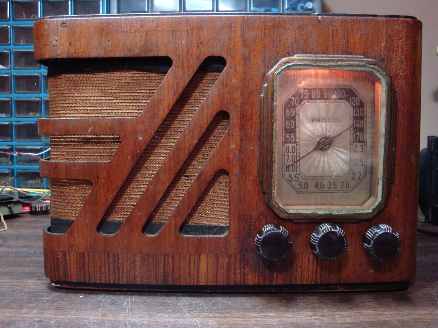
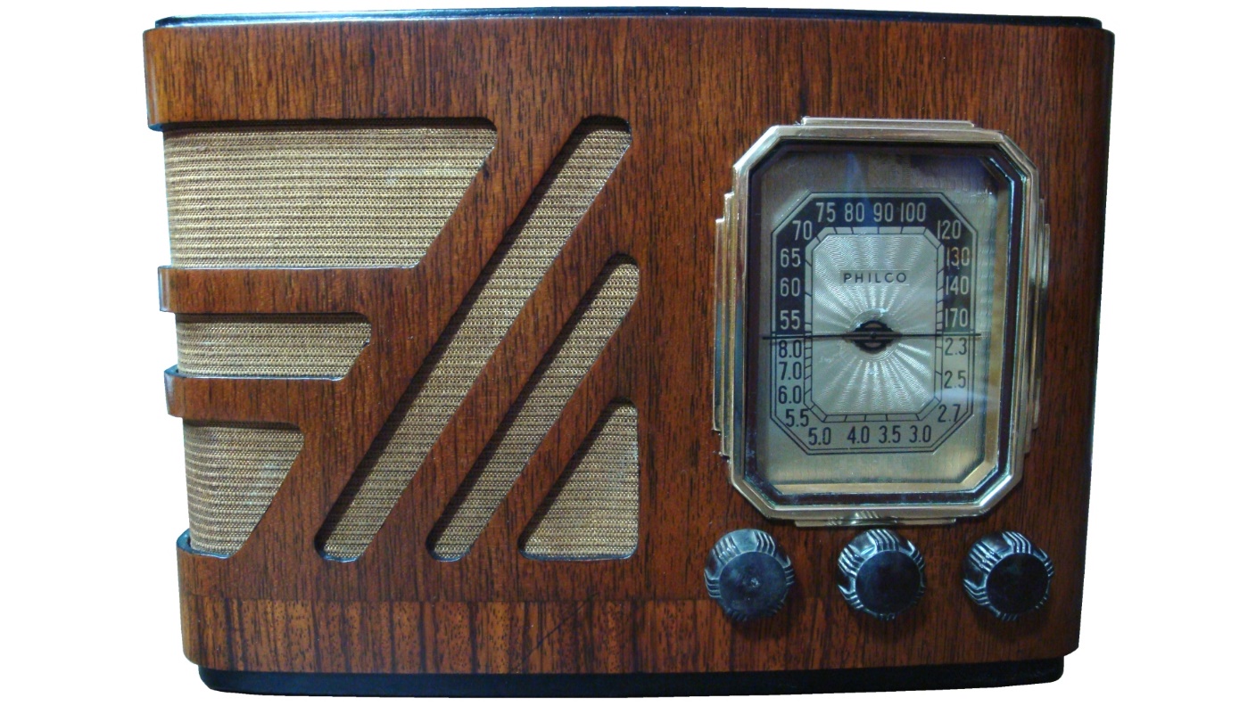
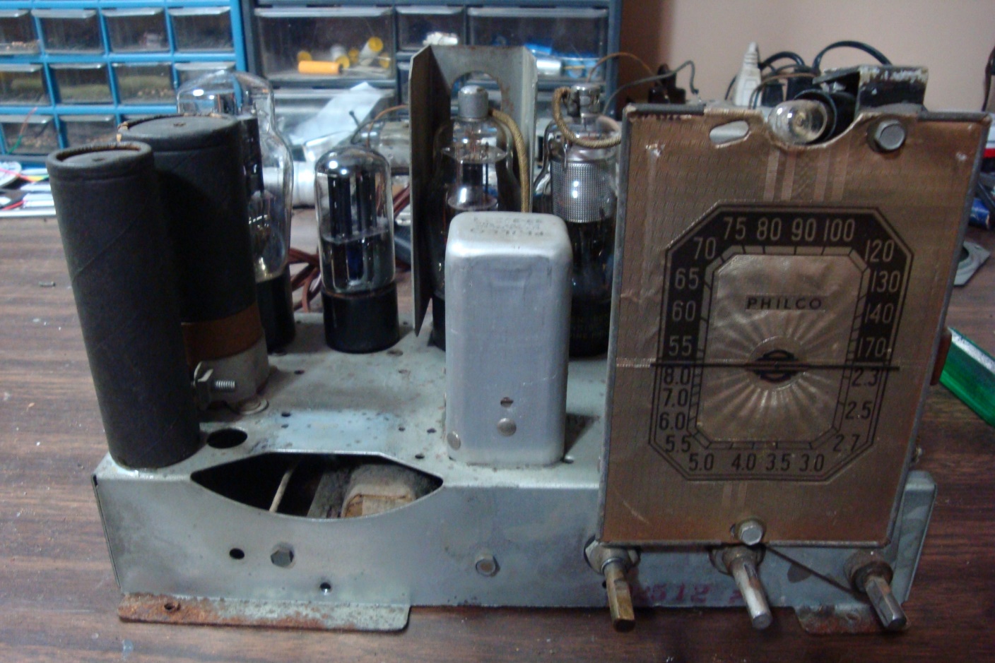
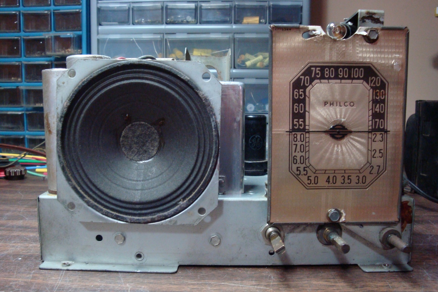
The subject Philco model 38-14T. This photo was taken after I had restored the chassis (notice the dial lamp is illuminated) but before I had refinished the cabinet.
As you can see from the photo above, the radio had some obvious cabinet flaws but looked quite restorable. The chassis was also clean and had all its tubes.
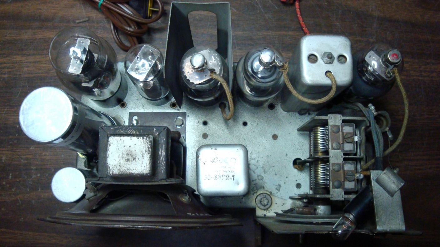
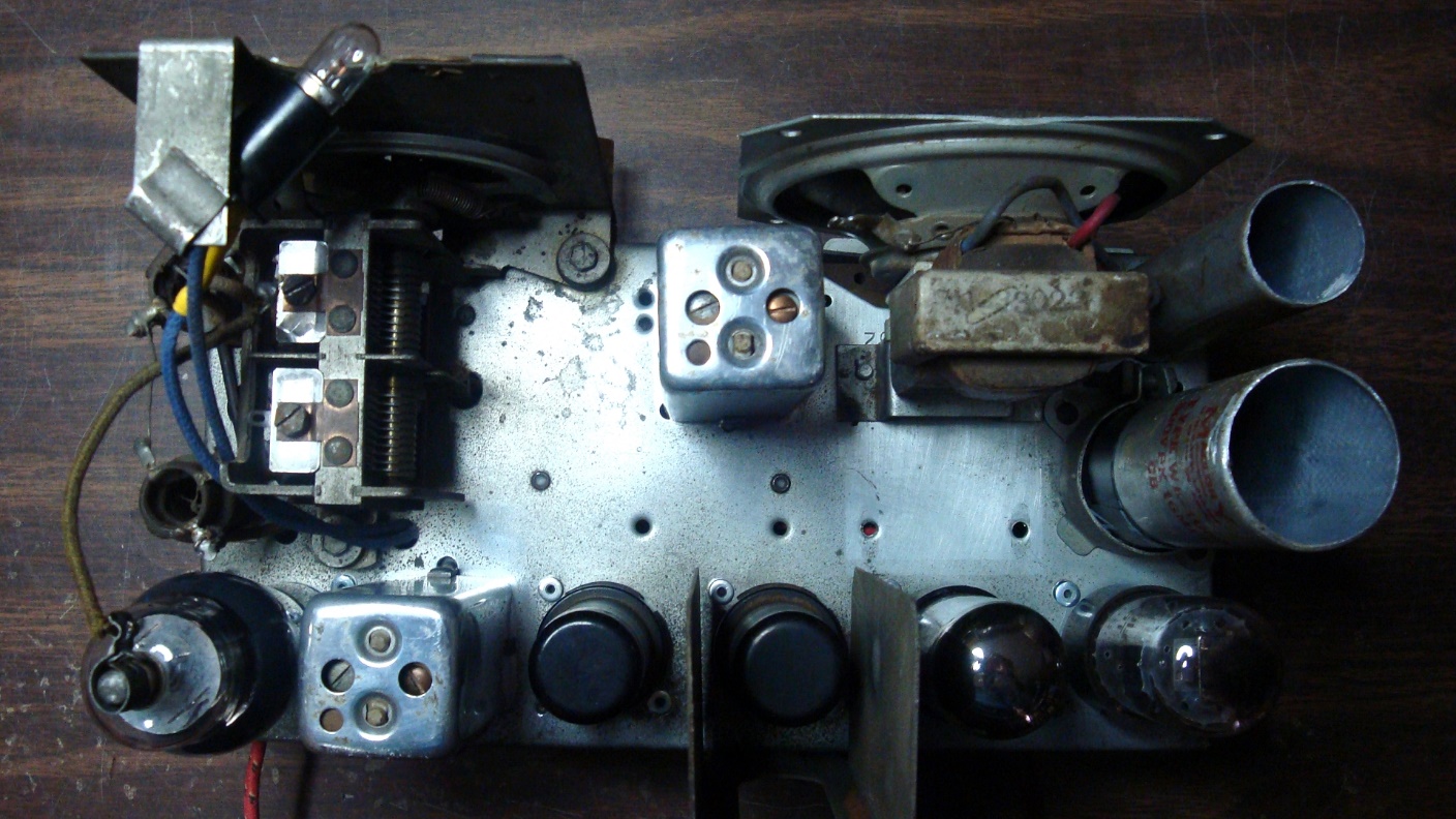
Top view of the 38-14 chassis.
Upon close examination of the chassis, however, I began to find issues. I noticed that someone had attempted to work on the radio previously. That in itself was not necessarily a problem, but the missing filament dropping resistor definitely was.
Look carefully at top center of the chassis. Notice the empty hole in between the filter choke and the off-on-volume control? The filament dropping resistor is supposed to be inside there. Instead, there was only an empty can.
If I hoped to be able to rescue this radio, I needed to come up with some sort of a plan.
Then I thought of the “All American Five” radio circuit.
The “All American Five” was a five-tube radio circuit which eventually came into common use among many radio manufacturers, with slight variations. The earliest versions of this AC-DC circuit were radios such as Philco’s model 54C. This radio required dropping resistors to lower the filament voltages to a level usable by the tubes then in use.
As time went on, newer tubes were developed with higher filament voltages, which eventually eliminated the need for dropping resistors in the filament circuit of these radios. The typical lineup included a 12SA7 converter, a 12SK7 IF amplifier, a 12SQ7 detector and first audio amplifier, a 50L6GT audio output tube, and a 35Z5 rectifier. When the filament voltages of these tubes were added together (12 + 12 + 12 + 50 + 35), the result was 121. So, when the filaments of these tubes were connected in series, they could be operated from a then-typical 115 to 117 volt AC line, without dropping resistors. Later on, miniature versions of these tubes were developed, including 12BE6 (converter), 12BA6 (IF), 12AV6 (detector & 1st audio), 50C5 (output) and 35W4 (rectifier).
In any event, I decided that I was going to convert this 38-14 to use the octal versions of All American Five tube types.
Let’s look at the 38-14 schematic.
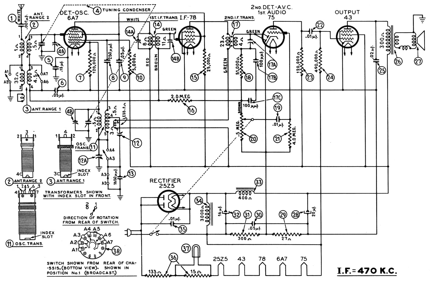
Original Philco 38-14 schematic.
The radio uses a 6A7 converter tube, as did millions of radios built in the 1930s. It was a popular tube in its time and did a good job in typical consumer radios. Because its construction is different from the 12SA7, I would need to find a 12 volt substitute for a 6A7.
Fortunately, that was easy – the 12A8G or 12A8GT is essentially an octal based, 12 volt filament version of the 6A7 and should make an excellent substitute for same.
The remaining tubes could be replaced quite easily with changes to octal sockets. The 78 IF amplifier could be replaced with a 12SK7; the 75 detector/first audio with a 12SQ7; the 43 output with a 50L6GT; and the 25Z5 rectifier with a 35Z5.
Compare the original 38-14 schematic with the modified schematic below.
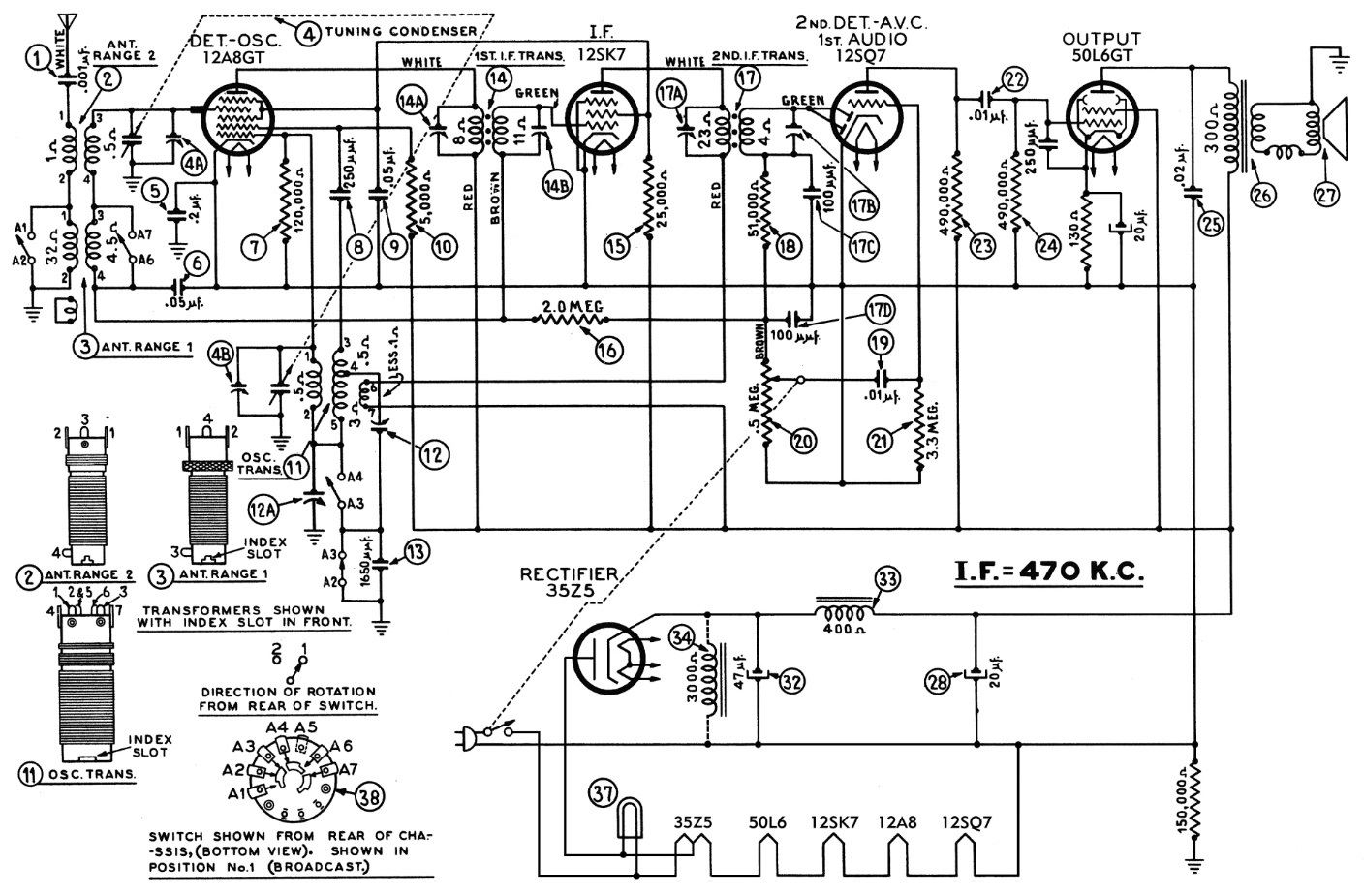
Modified Philco 38-14 schematic using octal “All American Five” tubes.
There are basically no changes in the schematic from the set’s front end up to the 12SQ7 tube. Here, you begin to see changes which allow the substitute tubes to work properly in the set. The 75 tube’s 4 megohm grid resistor (21) is changed to 3.3 megohms for the 12SQ7. Likewise, the 75 tube’s plate resistor (23) is changed from 190K to 490K.
The 50L6GT audio output circuitry is changed to add a 250 pF capacitor, a 130 ohm cathode resistor, and a 20 uF, 25 volt electrolytic capacitor as shown above.
The power supply circuit is greatly simplified. The bias network consisting of resistors (29) and (31) is eliminated, as is the filament dropping resistor (36). The dial lamp is now powered by a tap on the 35Z5 filament. The power switch is changed from the neutral side of the AC line to the hot side for safety. Finally, a 150K resistor is added from the neutral side of the line (B- of the radio) to chassis ground.
With these plans in mind, I began to disassemble the 38-14 chassis. Soon, I had removed everything but the tuning condenser, the antenna and oscillator coils, and a few other items.
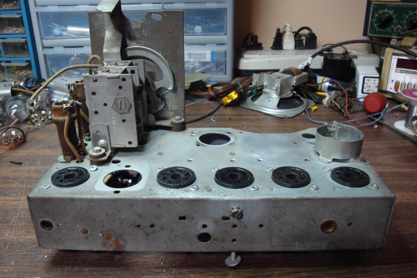
An almost bare 38-14 chassis. The original tube sockets have been replaced with octal sockets.
I removed all the original tube sockets, replacing them with Amphenol type MIP octal sockets.
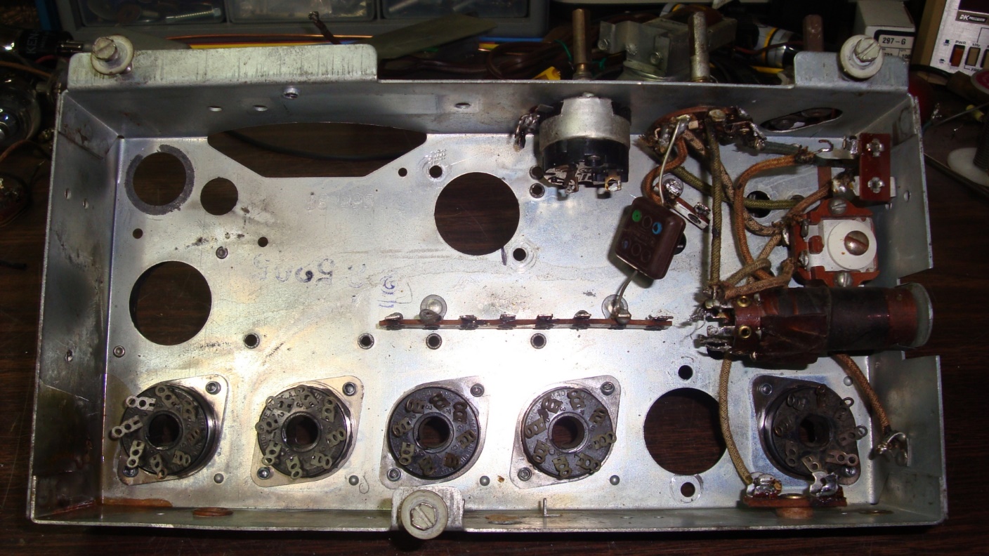
Underside of the 38-14 chassis with its “new” octal tube sockets.
Once the replacement tube sockets had been attached to the chassis, I began to rewire the chassis and add new capacitors and resistors.
Since the original filament dropping resistor was missing – only its can cover remained – I decided to change the IF transformers used in the radio. The “new” IF transformers were taken from a 1940s Philco parts chassis. I did not have to do this, but having the 2nd IF transformer mounted on top of the chassis instead of underneath was an idea which appealed to me. The “new” 2nd IF transformer I used in this radio included a trimmer capacitor across the transformer primary, something which the original did not have.
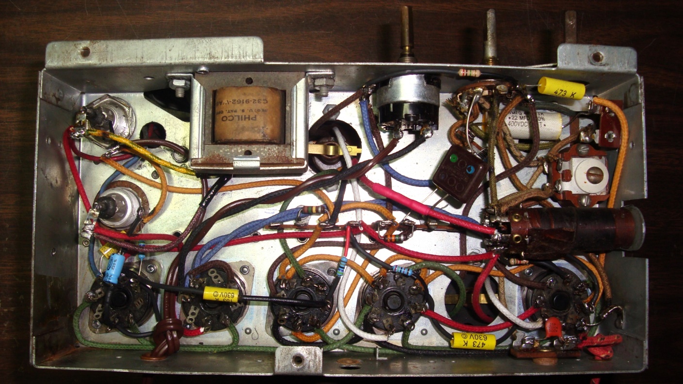
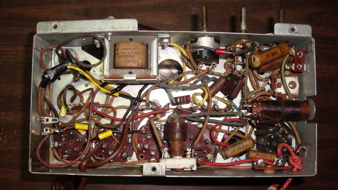
The rewired, rebuilt, and modified 38-14 chassis as viewed from underneath.
Before long, I had the chassis completely rewired underneath. The “new” 2nd IF transformer was mounted where the filament dropping resistor had originally been mounted on the chassis.
An important point needs to be made here. If you choose to do this modification yourself, be sure and connect a wire from pin 1 of the 12SK7 socket to ground. Do the same at the 12SQ7 socket. In addition, use metal 12SK7 and 12SQ7 tubes. This will take advantage of the shielding used in both these tubes – the metal shell of each tube is connected to pin 1. Be warned that if you use glass 12SK7GT and 12SQ7GT tubes, you will likely experience uncontrollable squealing (oscillations) in your radio.
I was disappointed to discover that the speaker field coil was open. But thanks to the reimagined schematic, the new design could easily use a PM speaker instead of the original electrodynamic speaker, completely eliminating the field coil. Actually, the original design could also accommodate a PM speaker, because in this design, the field coil is connected between the output of the rectifier and B- and does not act as a filter choke. In other words, it is not really needed.
I had previously installed a PM speaker in a 38-14CB which also had a bad speaker, so I knew what needed to be done.
I found a donor speaker from a late 1940s Philco table model radio. I do not remember which model it was.
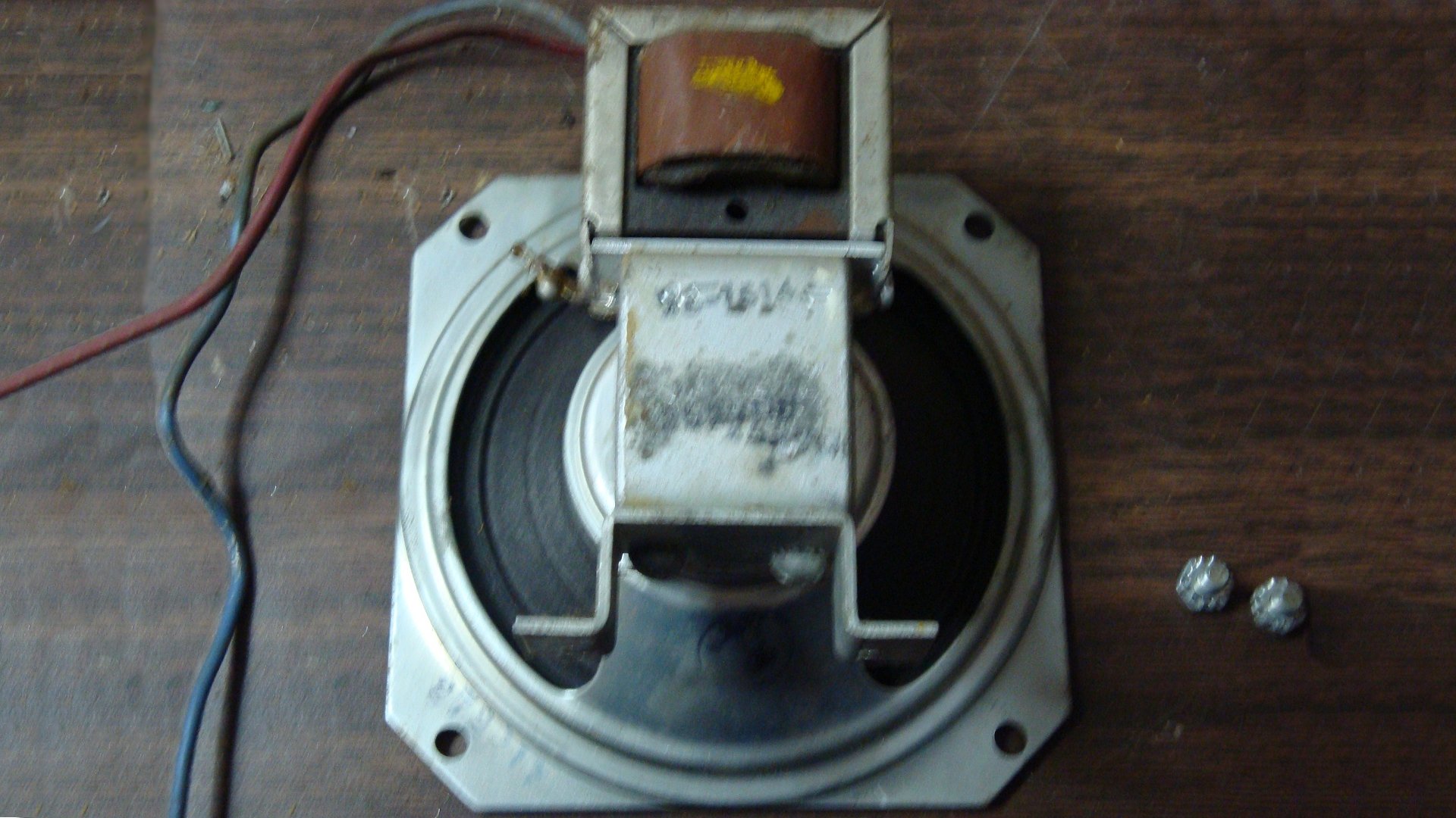
A permanent magnet (PM) speaker from a late 1940s five tube Philco radio. Its audio output transformer is a perfect match for the 50L6GT output tube.
This PM speaker mounted to the chassis with a bracket. This would work out well in the 38-14 chassis.
This is not the same 38-14 chassis, but it illustrates what is going to happen – the replacement speaker will be attached in the same spot as the original speaker.
I removed the original speaker.
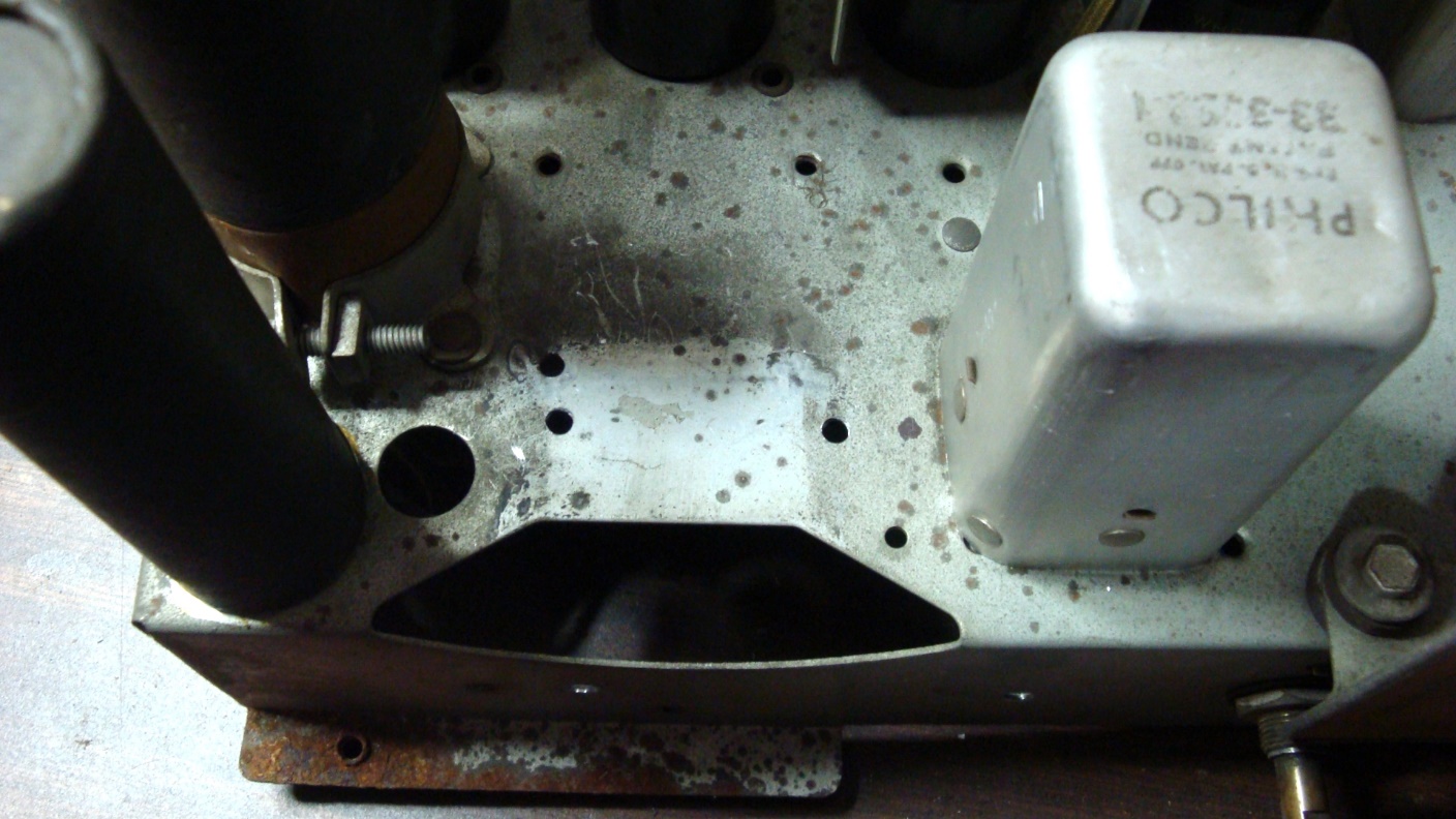
Two new mounting holes will have to be drilled in the chassis in order to mount the replacement speaker to the chassis.
I would need to drill two new mounting holes to allow the newer speaker to be attached to the chassis. This was taken care of in short order with a drill and the appropriate drill bit.
The 38-14T chassis with its replacement speaker.
Soon, the newer Philco speaker was mounted on the 38-14 chassis. Yes, it was smaller than the original, but I knew from previous experience that sound quality would be about the same.
The rebuilt and modified 38-14 chassis as viewed from the top. The electrolytic capacitors still need to be restuffed at this point.
The chassis was now looking more like a complete radio. I still needed to restuff the two main filter (electrolytic) capacitors. This may have been one of the first, if not the first, radio I worked on in which I cut off the tops of the electrolytics, restuffed the cans with new components, and then glued the tops of the cans back in place. This has been standard procedure for me now for many years.
The 38-14T chassis as viewed from the rear.
Soon, the radio chassis was finished. Best of all, it worked the first time power was applied. The radio was aligned, including aligning those “new” IF transformers to 470 kc, and the radio was almost ready to go.
In July 2011, I refinished the 38-14’s cabinet. It turned out very well as you can see below.
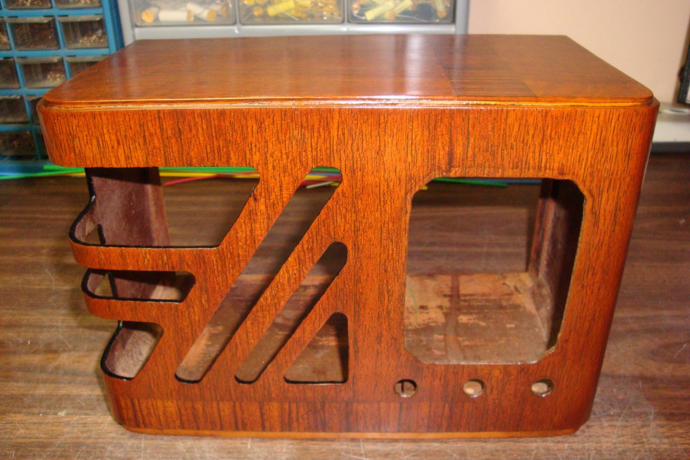
A freshly refinished 38-14T cabinet before the dark accents have been added at top and bottom.
I used Mohawk Medium Walnut Tone Finish (lacquer) over the entire cabinet, later adding top and bottom accents of Extra Dark Walnut as shown below. A careful application of dark brown nail polish (which is also lacquer) was added to the edges of the speaker grille cutouts. Deft gloss lacquer was used as a final finish.
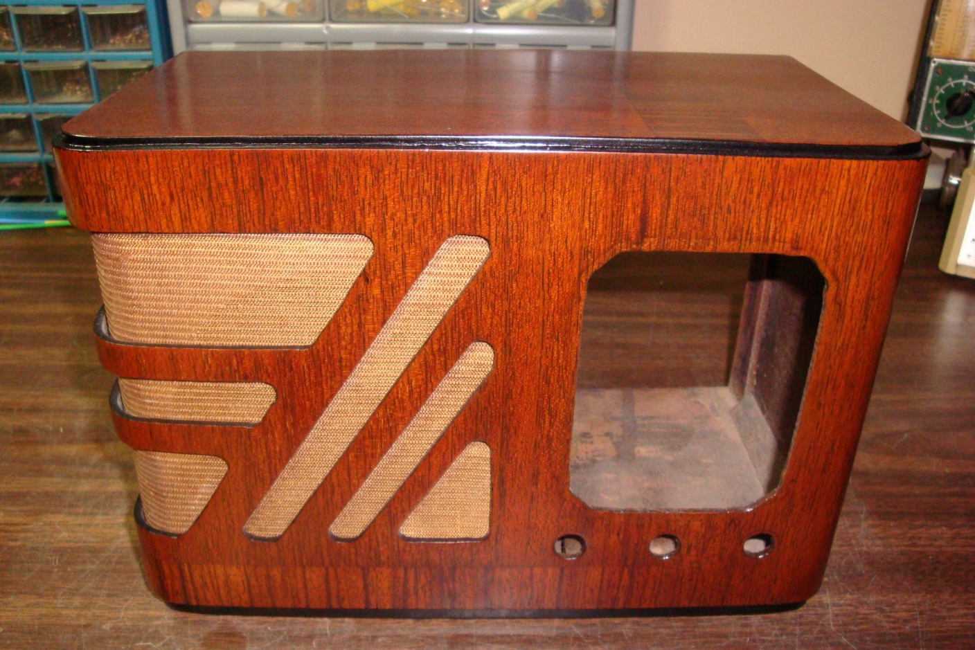
Now fully refinished, the 38-14T cabinet receives new (reproduction) grille cloth.
The chassis is placed inside the refinished cabinet just to get an idea of how the radio is going to look when it is complete.
I had purchased several patterns of cloth from Radio Grille Cloth Headquarters just before they went out of business several years ago. Among the patterns I bought was the Philco “Ribbed” pattern. I used a small piece in this 38-14 cabinet to improve its looks.
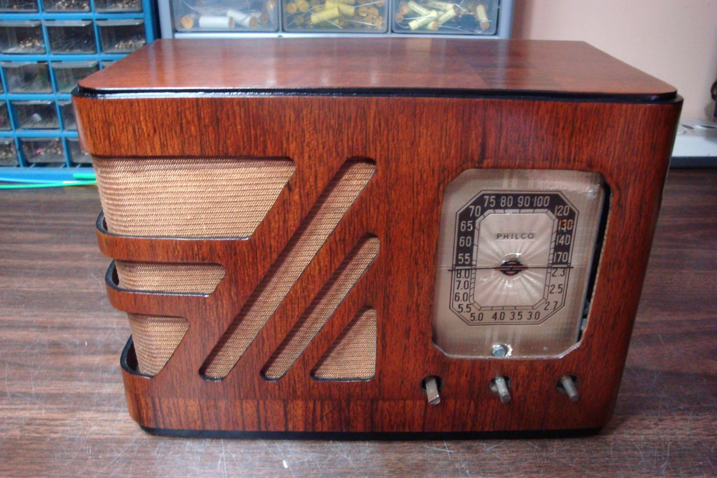
Finally, I cleaned up the escutcheon and reattached it to the cabinet, and then installed the chassis in the cabinet and put the knobs back in place.
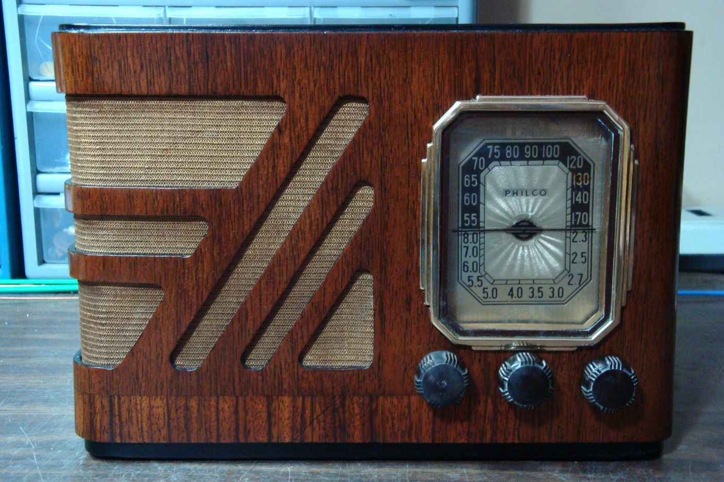
The finished product – the subject of this article.
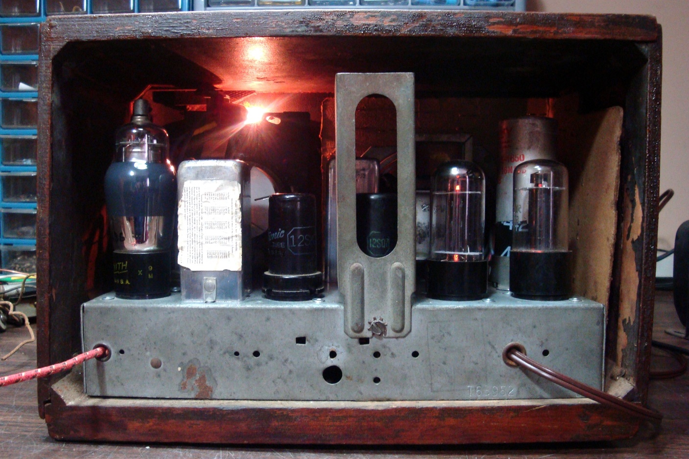
Rear view of the completed 38-14T while in operation.
The set looked like new once again and played very well. The Philco shield which had been in place for the 75 tube was no longer needed with the metal 12SQ7, but I left the shield in place anyway.
I kept the radio for a few years before eventually selling it. It was a fun project, and I would not hesitate to make this modification to another 38-14 if the opportunity arose.