Last time, I was ready to begin my partial rebuild of a Philco 38-116 chassis to use for testing the rebuilt 37-116 RF unit. I decided it would be best to take care of the harder parts first before moving on to easier tasks.
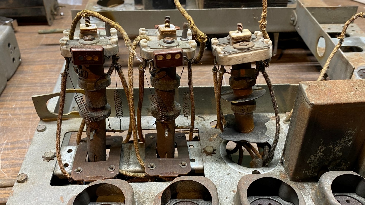
38-116 IF transformers with shields removed. Note the condition of the wires which come out of the tops of the shields.
I began by removing the aluminum shields from the set’s three IF transformers. I quickly found that the grid leads which are routed out of the top of each transformer were in pretty bad shape. Of the three, I was able to replace two of them. The third lead, connected within the 1st IF transformer, could not be easily replaced so instead of spending a lot of time with it, I merely sleeved it with heat shrink tubing, shrinking the tubing with a lighter.
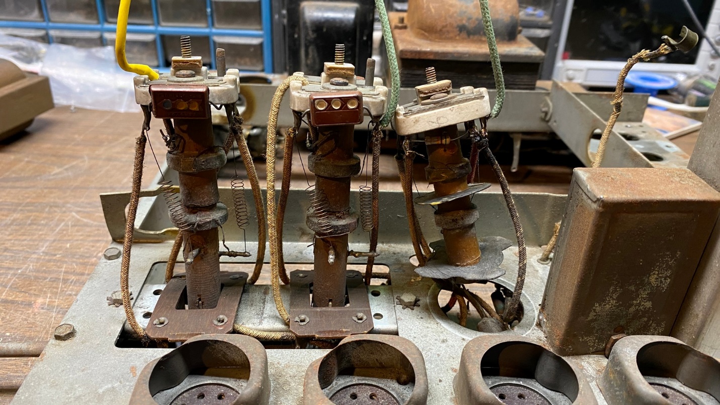
38-116 IF transformers with new grid wires.
Once the three grid leads were done, I put the transformer shields back over the IF transformers, being careful to properly route each of the grid leads through the proper holes. After reattaching each of the shields, I then soldered the grid ca connectors to each lead wire. You can see the results below.
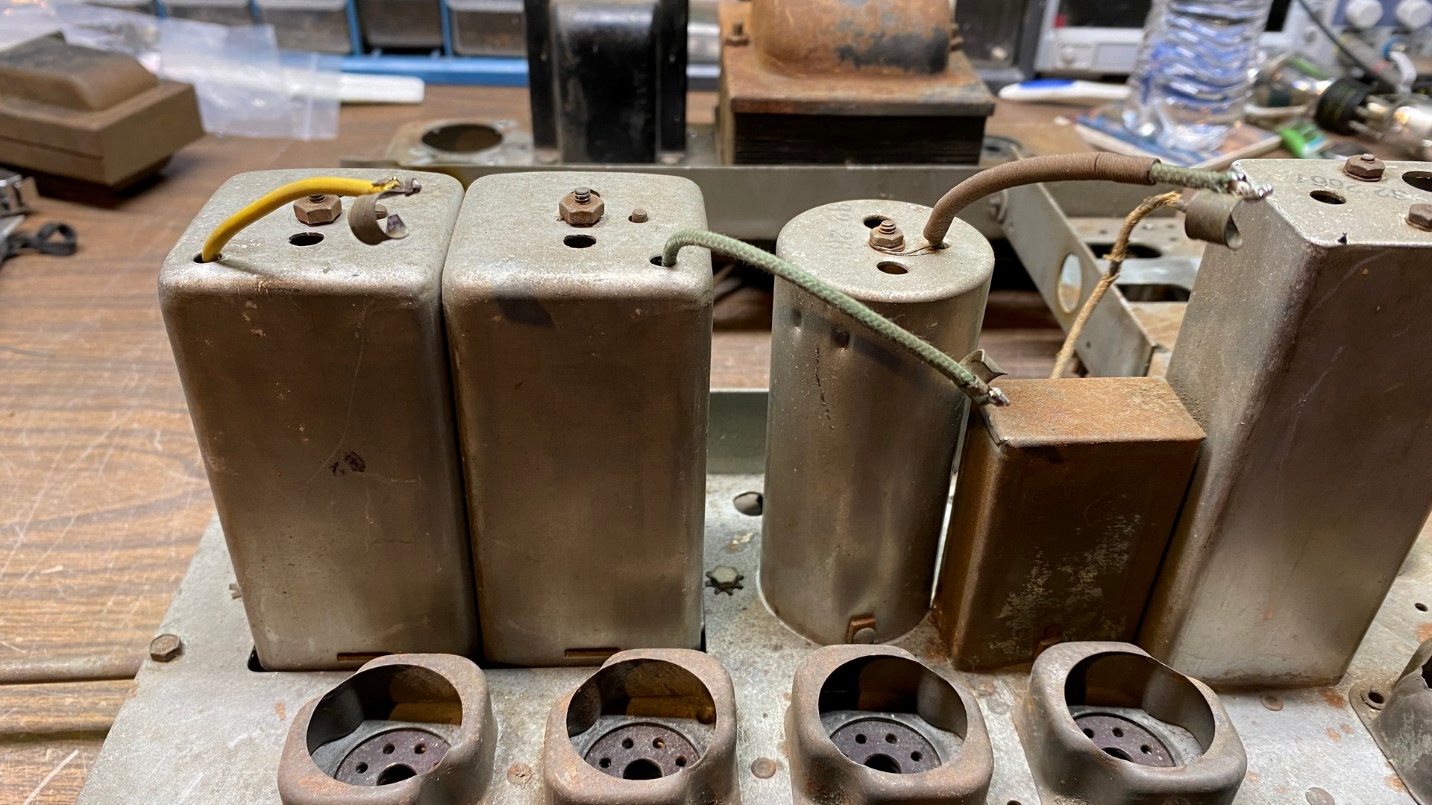
38-116 IF transformers with shields in place, and with grid cap connectors soldered to each wire.
As I will be using this chassis merely for testing purposes, I saw no reason to polish the IF transformer shields as I normally do in the course of a radio restoration.
The next job was to begin replacing the capacitors and resistors under the chassis.
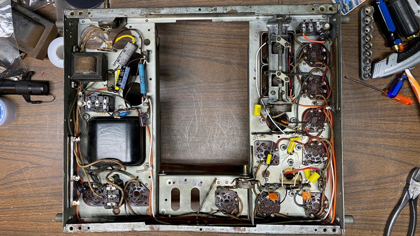
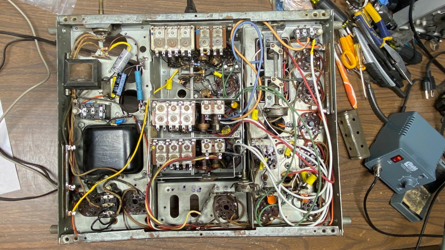
Bottom of 38-116 chassis. Most capacitors and resistors have now been replaced.
There is a rectangular can which contains three capacitors. This is part of the radio’s Magnetic Tuning circuit. I removed this can, removed its old guts, installed three new capacitors with new lead wires, and then reinstalled the can on top of the chassis.
I did not bother to restuff any of the electrolytic capacitor cans – again, because this is only going to be used for testing purposes. Therefore, you see individual electrolytics under the chassis. Normally I consider this practice to be sloppy work. But for this chassis, it does not matter.
I was not sure what to do about the 350 ohm field coil which the set normally uses in its B- circuitry. The only suitable thing I had was a 10 watt 330 ohm resistor. So, I installed it. I was hoping that since this chassis does not have any of its audio circuitry hooked up, that that would be sufficient.
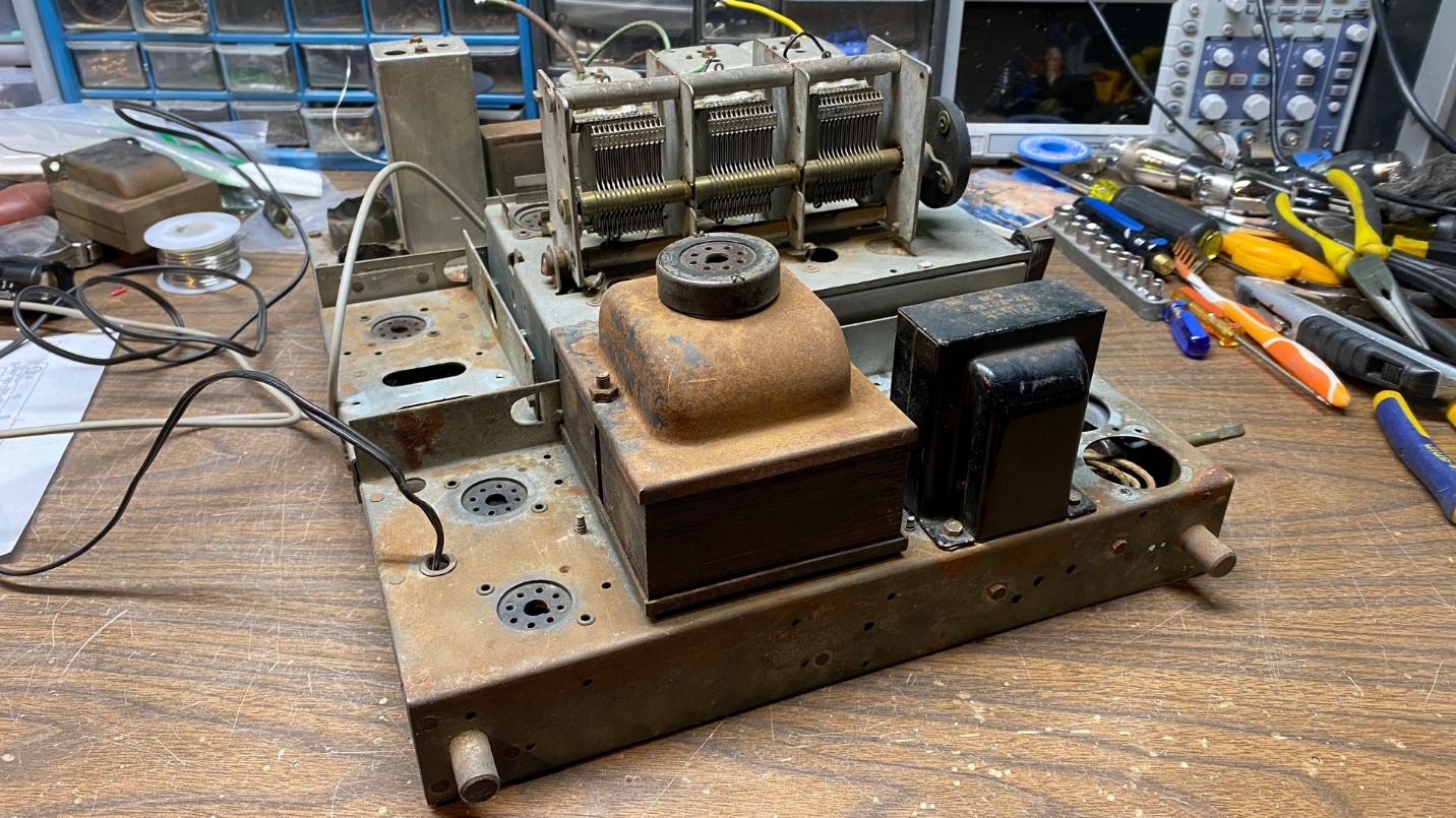
Soon, the chassis was completely rebuilt, and it was time to install the 37-116 RF unit.
Installing the rebuilt RF unit into the chassis.
I attached a bolt to the back of the RF unit to hold it in place, and then flipped the chassis upside down again to begin connecting the fourteen wires from the RF unit to their proper places under the chassis.
RF unit wired up underneath the chassis.
I purposely left the wires long. If this RF unit works, and if it is ever needed, it will be an easy matter to then trim the wires to fit properly. It is not so easy to lengthen a wire lead. Oh yes, it can be done, but in this case it is better to have the wires too long than too short.
The complete setup, almost ready for testing.
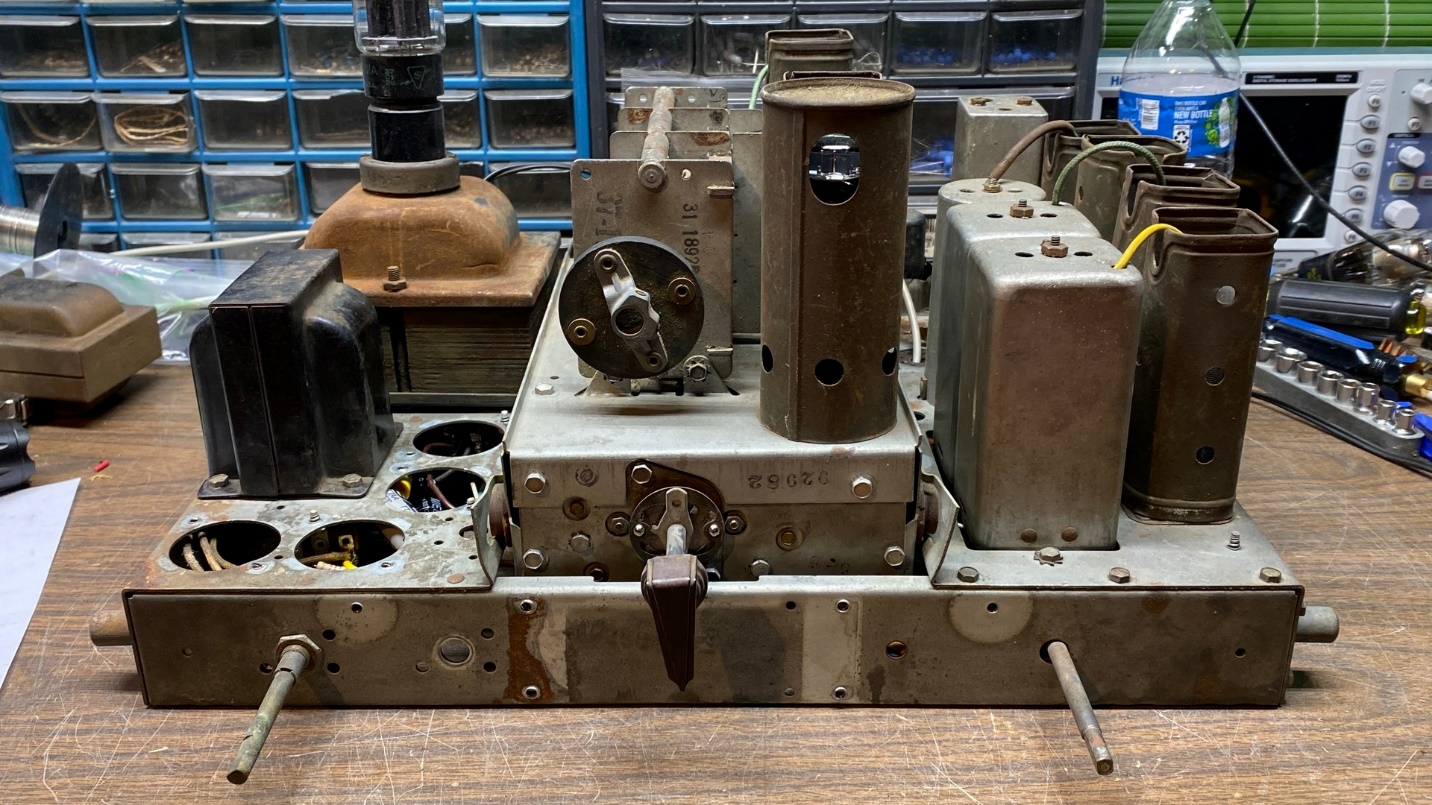
Once all the wires were connected under the chassis, I flipped the chassis back to its proper upright position. Next came the process of finding enough tubes and tube shields.
I soon had enough tube shields but found that I did not have a 6L7G tube! Not only did I not have a 6L7G in my tube stash, I do not own any other radio that uses a 6L7G.
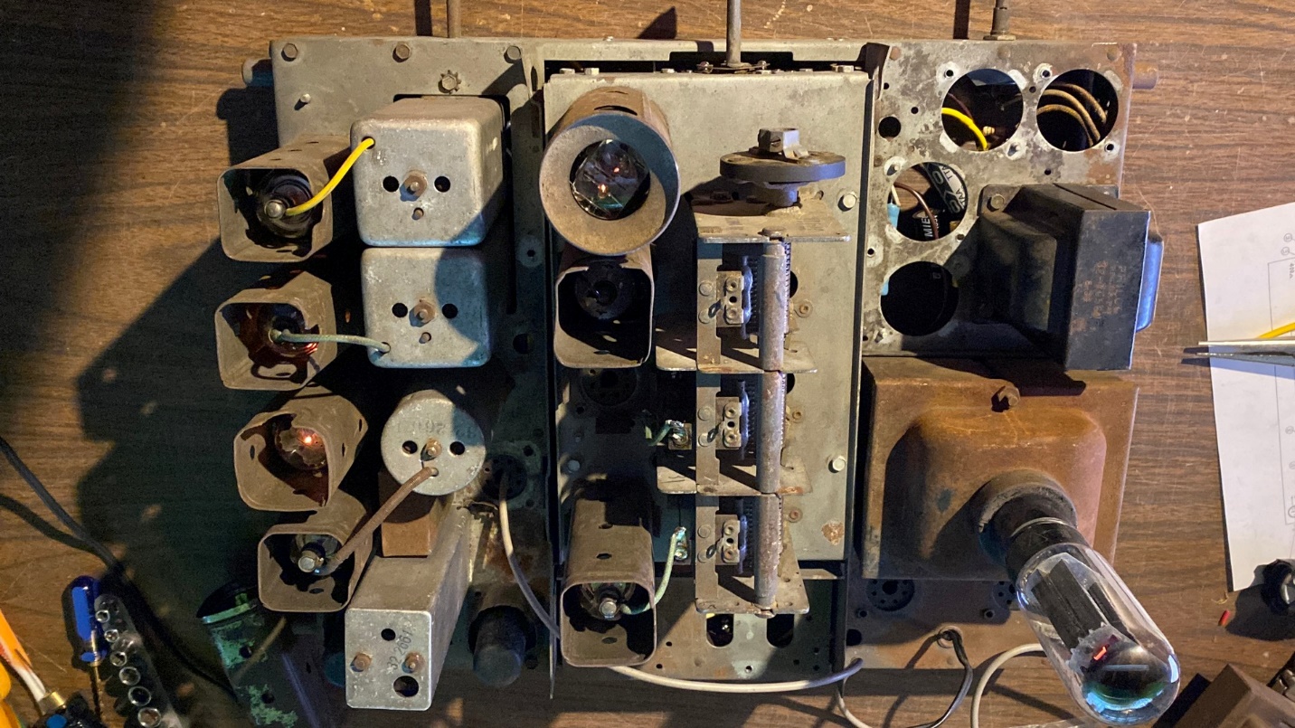
Even without a 6L7G tube, I tried the unit out without connecting it to my amplifier. No smoke, sizzling, explosions, or shorts were noted.
I decided to go ahead and apply power, just to see if anything was obviously wrong. I plugged the test chassis into my Variac and turned on the radio chassis and the Variac. I slowly brought the voltage up to 110. You can see some of the tube heaters illuminated in the photo above. Happily, there was no smoke, no sizzling, no obvious issues. Best of all, the 330 ohm, 10 watt resistor was only barely lukewarm after this test. I expect it to get warmer once I have a 6L7G in hand and try the test in earnest.
Unfortunately, I can proceed no further for now without a 6L7G tube. (A 6L7G has been located and should soon be on its way here.) In addition, I had another chemo session the next day (I am writing this on January 27th). So, this project is once again on hold until I get a 6L7G tube and until I recover enough from chemo to try again.