It was time to have fun with coils! The coils in many Philco radios made between 1928 and 1936 often fail in one way or another. I expected to find some bad coils in this Philco 90, and it did not disappoint.
I started with the antenna coil. An initial test revealed its primary was open. In this case, the primary winding of the coil is connected between the antenna terminal and ground.
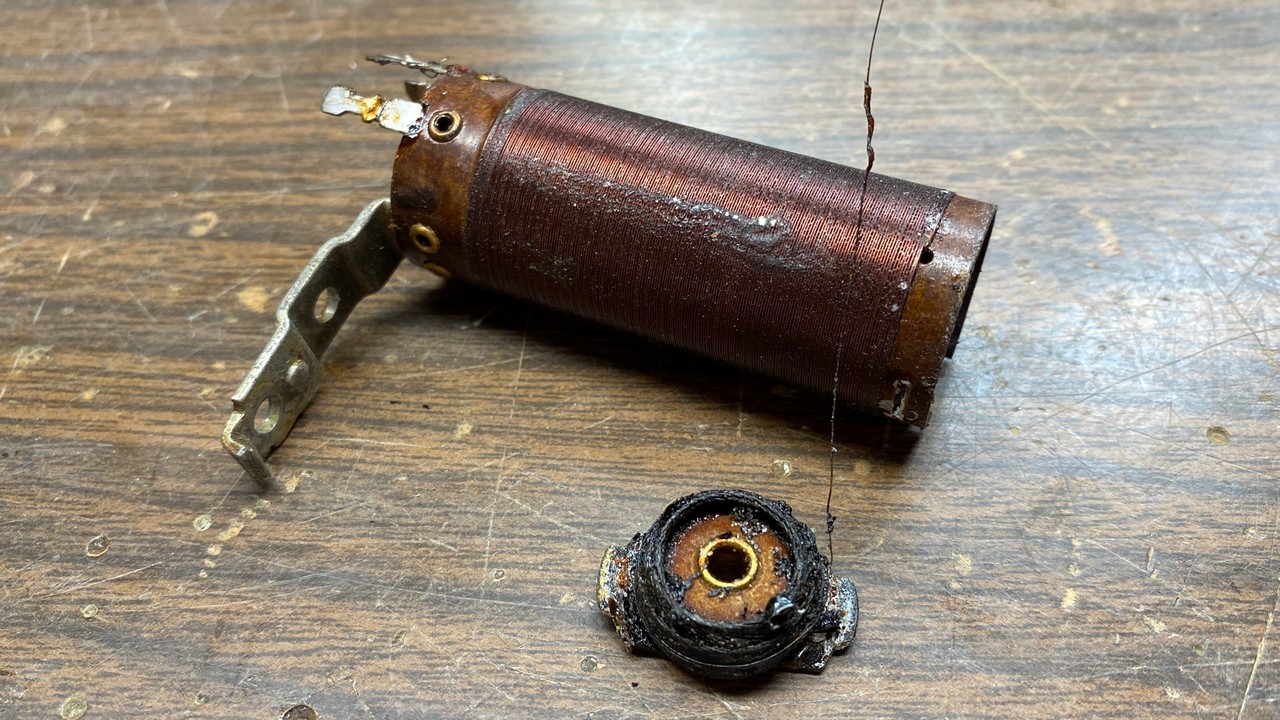
I removed the coil from the chassis, and carefully removed the primary coil form from the top of the main coil form upon which the secondary was wound. As you can see in the photo above, the primary of the coil was obviously burned badly. This was likely caused by a direct lightning strike to whatever outdoor longwire antenna was connected to the radio at the time.
This could be repaired by scramble winding about 250 turns of 38 gauge wire on the small form. In this case, however, I decided to get lazy and use a scramble wound winding from onother Philco coil which I happened to still have on hand.
I carefully removed the small form from the other coil by first unsoldering the long wire leads, then carefully and slowly pushing up on the form from the bottom to release one of its two mounting tabs. If this is done very carefully, once one tab is free of the main coil form, the primary form may then be easily pulled out.
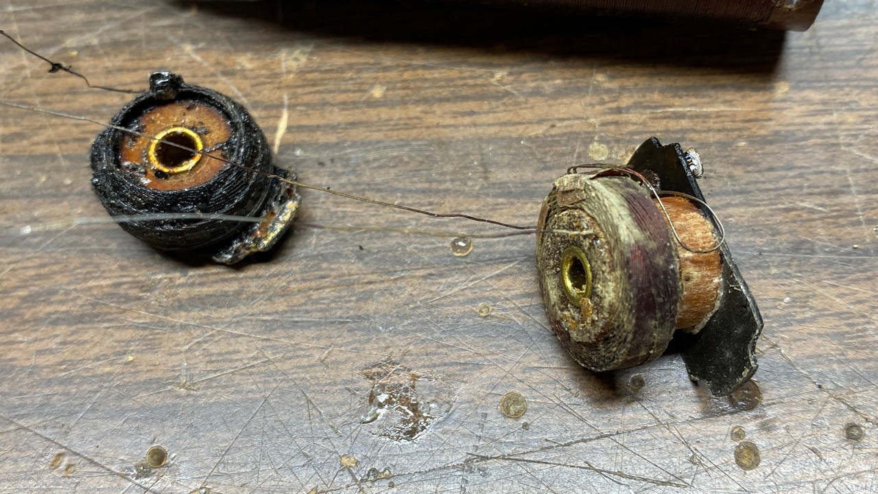
The old Philco 90 antenna coil primary (left) and its replacement (right).
I did not remember which Philco model that coil had come from. It was unusual in that the primary was tapped. I would not be using the tap, and I knew that its total amount of turns was not critical in this application.
Carefully, I pushed the replacement primary into the top of the main coil form until the tabs snapped into place. I then soldered the long leads onto the proper terminal on the bottom of the coil form. The finished product is shown below.
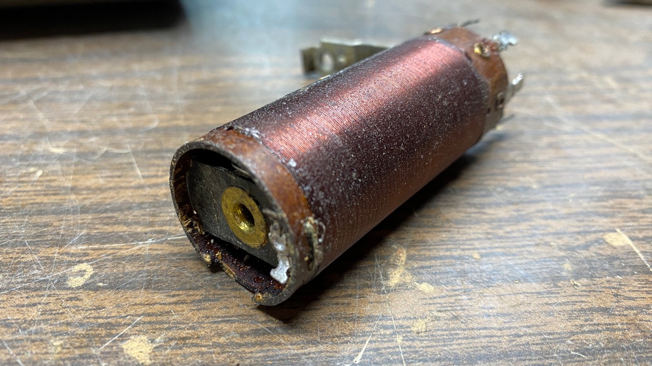
The repaired Philco 90 first antenna coil.
Using the primary winding from another coil saved me an hour or so of winding a new winding on the original form, as I have never owned a coil winder.
This Philco 90 uses a double tuned input circuit. This means there are two coils and two sections of the variable condenser tuning the input signal between the antenna terminal and the grid of the RF amplifier tube, a type 24. I checked the second antenna coil, which uses a single tapped winding, and it had good continuity.
I next tested the oscillator coil, and it too was good. I even removed it from the chassis to inspect it, to be sure it did not show any signs of imminent failure. I did not see any tell-tale green spots in the windings; everything looked fine. I noted that the oscillator coil primary was wound with 32 or 34 gauge wire, which is larger than the typical 36, 37, or 38 gauge wire used in many Philco coil primaries of the time period. The heavier primary wire has probably helped the coil survive for 92 years and still show good continuity.
The final coil in line was the intermediate or RF coil. This coil also had a bad primary winding. I would have no choice but to rewind this coil’s primary.
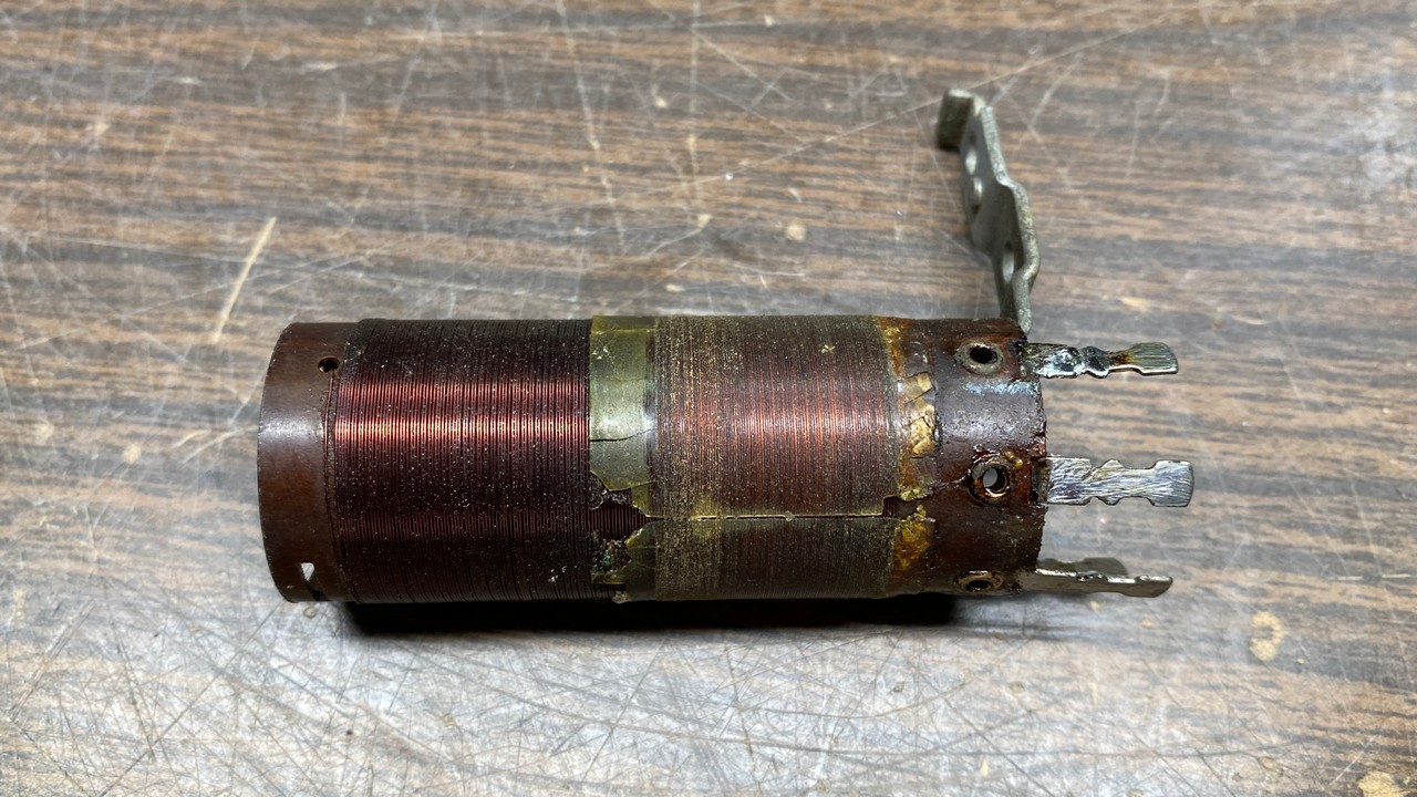
The Philco 90 RF coil, with its primary winding removed.
These Philco coils of 1928-1936 used nitrocellulose insulation between primary and secondary. The nitrocellulose often caused these coils to develop corrosion over the decades. I am going to admit here that I probably made a serious mistake in rewinding this coil, which I did not ever do in decades of rewinding Philco coils. That is, I did not remove the nitrocellulose this time but instead, wound my new winding over the old insulation. I did so because (a) I was out of mylar tape, (b) I did not wish to cut out a new insulator from plastic, and (c) the old insulator still looked good enough to reuse.
It took 95 turns of 38 gauge magnet wire to rewind the primary of the RF coil. When finished, it looked as shown below.
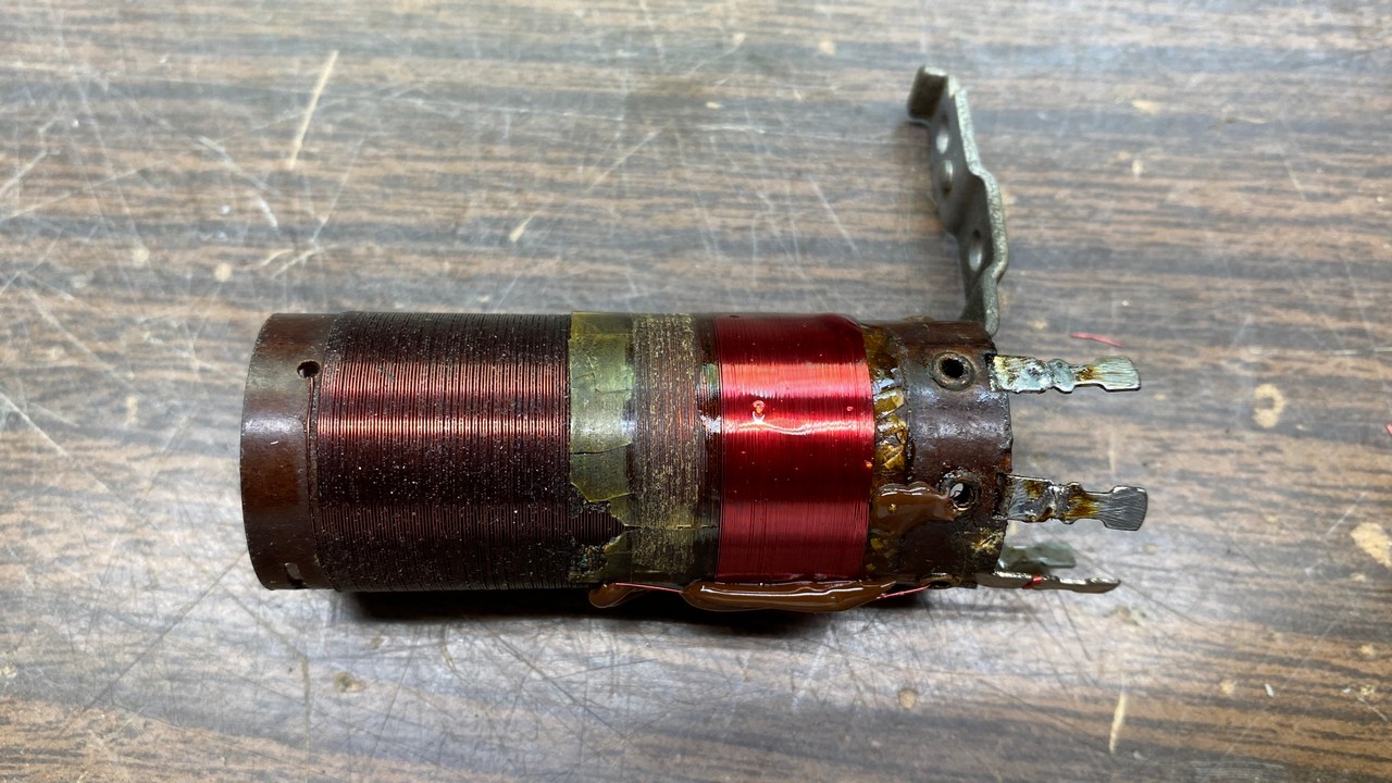
The rewound Philco 90 RF coil. I really should have used a new sheet of insulation between primary and secondary, but the old one still looked good.
Hot glue was used at the beginning and the end of the winding to hold the wire ends in place on the form. I also brushed lacquer over the new wire once it had been wound.
With the final coil in the 90 repaired and reinstalled, I noticed that I had not yet rebuilt the set’s tone control.
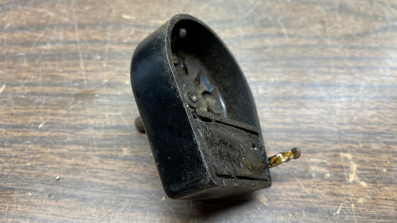
The Philco 90 tone control.
Depending on when a Philco 90 was manufactured, it may contain one of the 1931 and later tone controls using a metal frame, or one of the early units with a bakelite housing. The bakelite tone controls were used in 1930 Philco models such as the 77 and 96, as well as model 111 and early production of model 112. As you can see in the photos, this is an early Philco tone control.
The unit contains three capacitors encased in a black tarry wax substance. The capacitors cannot be easily removed from these. You have two choices when faced with the rebuilding of one of these – either place it in an old toaster oven to heat the unit up enough to pull the insides out, or carefully dig out the old components. I chose the latter.
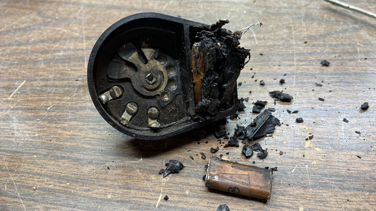
Digging the capacitors out of the tone control.
Once I had finished digging the old capacitors out of the tone control, I decided to remove the control shaft of the control so I could give the unit a thorough cleaning. It needed it since the entire control had tarry wax residue all over it, inside and out.
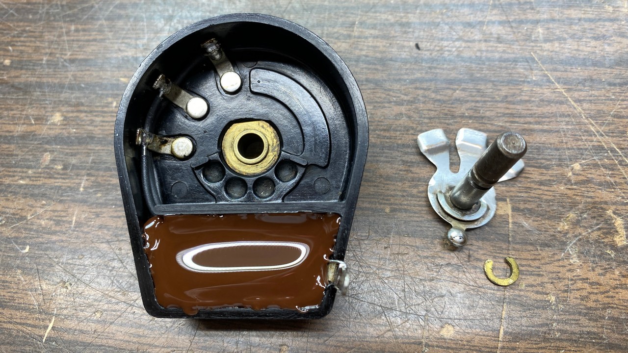
It was not easy to remove the C-clip holding the control shaft to the tone control. But with patience and perseverance, I finally prevailed. The photo below shows the C-clip, the control shaft, and the tone control itself separated from one another for the first time since 1930 or 1931, depending on exactly when this control was manufactured.
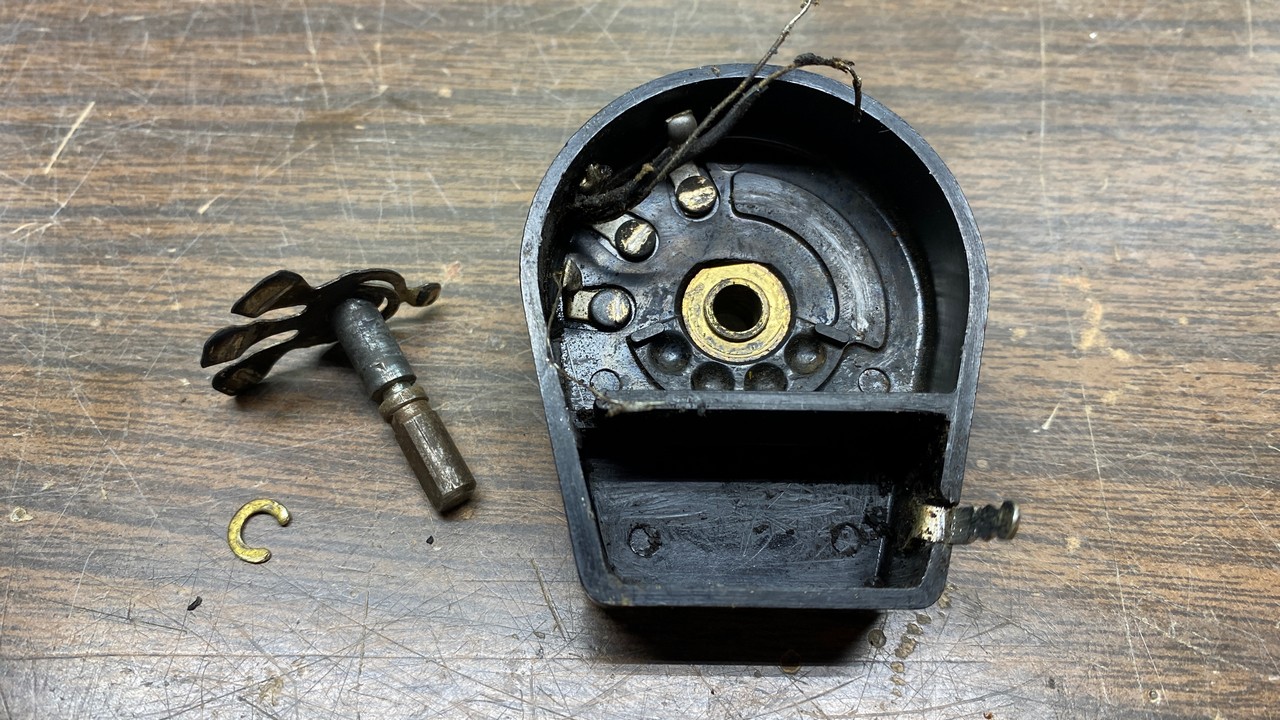
The disassembled tone control, ready for cleaning.
I lightly rubbed the three contact points inside the tone control with 0000 steel wool, vacuuming the control out thoroughly afterwards. I also rubbed the “fingers” of the control’s contacts, which were connected to the control shaft, with the same steel wool to clean them.
Next, I went over the entire control body with Q-tips and mineral spirits. This cleaned away the waxy residue.
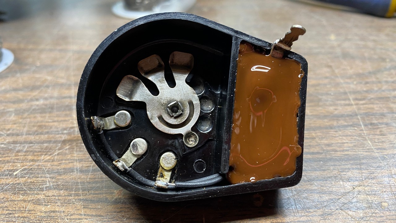
When finished, the control body looked as shown below.
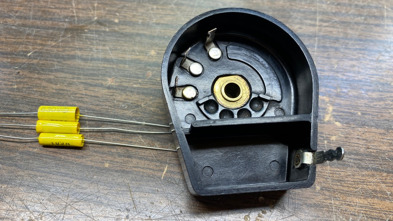
The cleaned tone control, ready for reassembly, with three new capacitors which will be installed inside it.
I selected three replacement capacitors for the tone control – a single 0.015 uF capacitor and two 0.01 uF capacitors – for use inside the tone control. I lengthened the lead of the 0.015 uF capacitor with 22 gauge bus wire as this unit connects to the first tone control terminal and needed the longest lead length. Black heat shrink tubing was placed over the leads of the capacitors which would connect to the three tone control terminals. This was necessary to keep the leads from shorting together. The three leads of the other ends of each capacitor were twisted together; this end would soon be soldered to the metal tab at the bottom of the control.
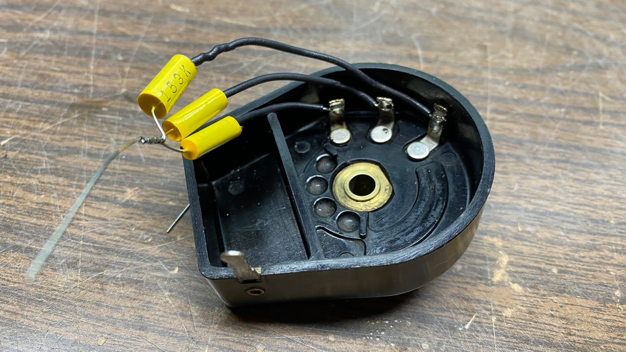
New capacitors are being installed into the tone control.
The wire leads were soldered to their respective solder points, and the capacitors were pushed into the cavity where the original capacitors once resided.
New capacitors in place inside the tone control.
Once the new capacitors were installed, the lower portion of the control was sealed with hot glue.
The new capacitors are now sealed inside the tone control.
Finally, the control shaft was reinstalled into the control and the C-clip put back into place to hold the shaft.
The rebuilt tone control, ready to reinstall in the radio.
And with that, I have taken up more room than usual, so I must bring this story to a close for now. Next time, I will reinstall the tone control in the radio chassis, and begin the final steps of the rebuilding process of this Philco 90. Stay tuned!