So, what can be better than owning a 1962-64 Fisher FM-50-B FM Stereo tuner? Why, owning two FM-50-B tuners, of course!
I have owned an FM-50-B for a few years. It was originally purchased as a parts set; I ended up repairing/restoring it and found it to be a pretty decent tuner. The FM-50-B was Fisher’s entry level model, with their TrioMatic front end (no RF amplifier) and four stages of IF amplification. It also has a three tube multiplex decoder for FM Stereo reception and a single 12AX7 audio preamplifier tube ahead of the audio output jacks.
A month or two ago, I acquired another rough FM-50-B which I had intended to use as a parts set, as I had a Fisher FM-200 which needed a bottom cover. When the tuner arrived, it obviously needed help but did appear to be restorable. Reluctantly, I removed the bottom cover and attached it to the bottom of my FM-200, thus completing it. I set the FM-50-B aside, thinking that if I came across another bottom cover, that I would go ahead and fix it up.
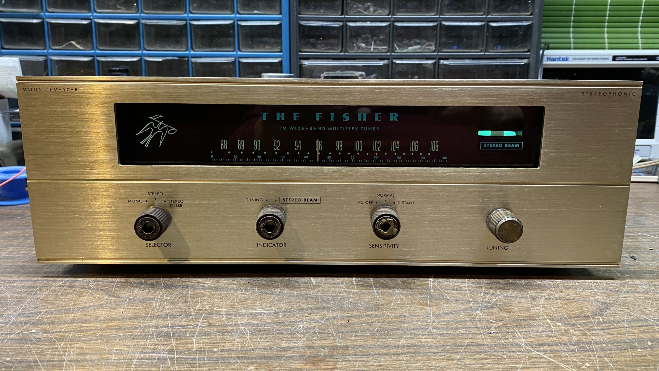
 The Fisher FM-50-B, as it looked when it arrived.
As it happened, I found and purchased a very rough 202-R tuner later on which was too far gone for an economical restoration. Since it had a bottom cover, I installed it on my FM-200 and returned the FM-50-B cover to its original FM-50-B tuner.
After my last chemo treatment, I had a few days where I felt good enough to do a few things. As I needed to take care of a few things around the house, I chose to do this and postpone more work on my ongoing Philco 38-690 project for a couple weeks. Then, having successfully installed two new traverse rods in our living room, I only had a couple days left before my next chemo treatment.
I decided to see if I could get this FM-50-B going over the weekend.
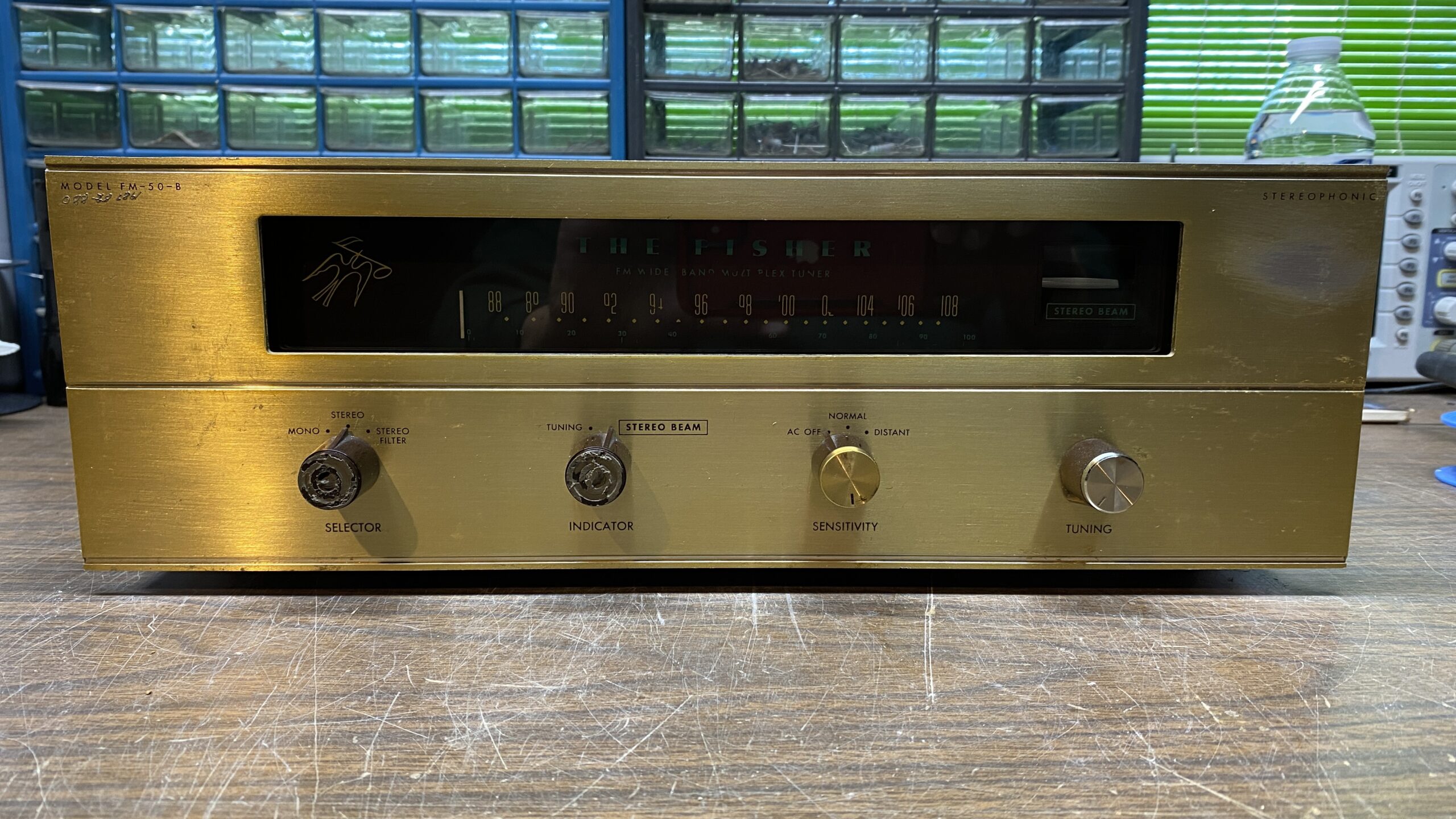
 The tuner is missing almost all of its tubes but appears to be in good shape overall.
Looking the tuner over, I made mental note of several issues it had. Cosmetically, its brass anodized aluminum front panel had a badly worn spot, and someone had etched their social security number into the upper corner of the panel. The dial scale was missing some numbers, as well as almost all of the logging scale. The original knobs were gone, replaced by knobs from early Fisher transistor equipment. The chassis itself was a bit dirty and had only a few rust spots. It had no tube shields, or bottom feet, and all tubes were missing save for the EM84A indicator tube.
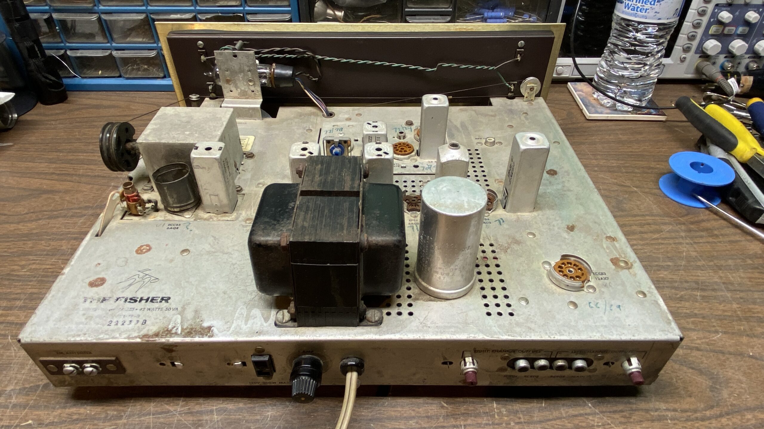 Back view of the FM-50-B chassis
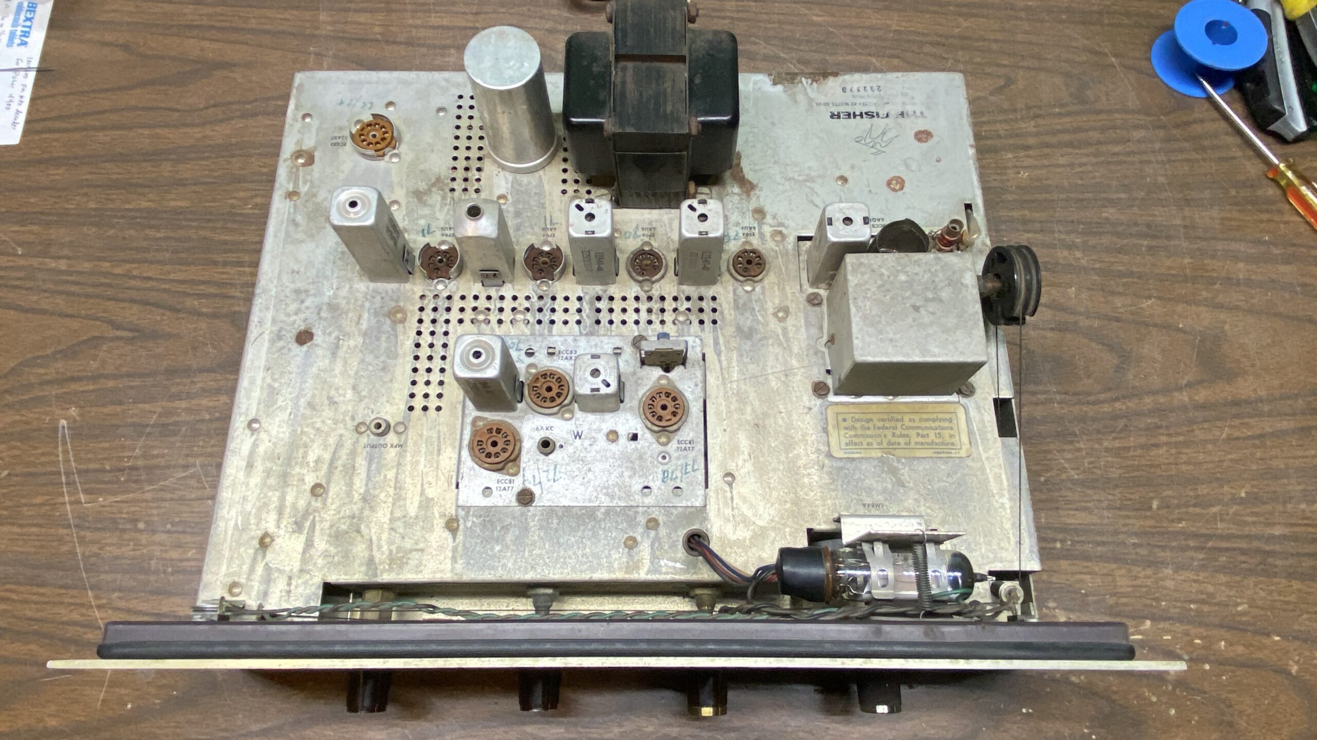
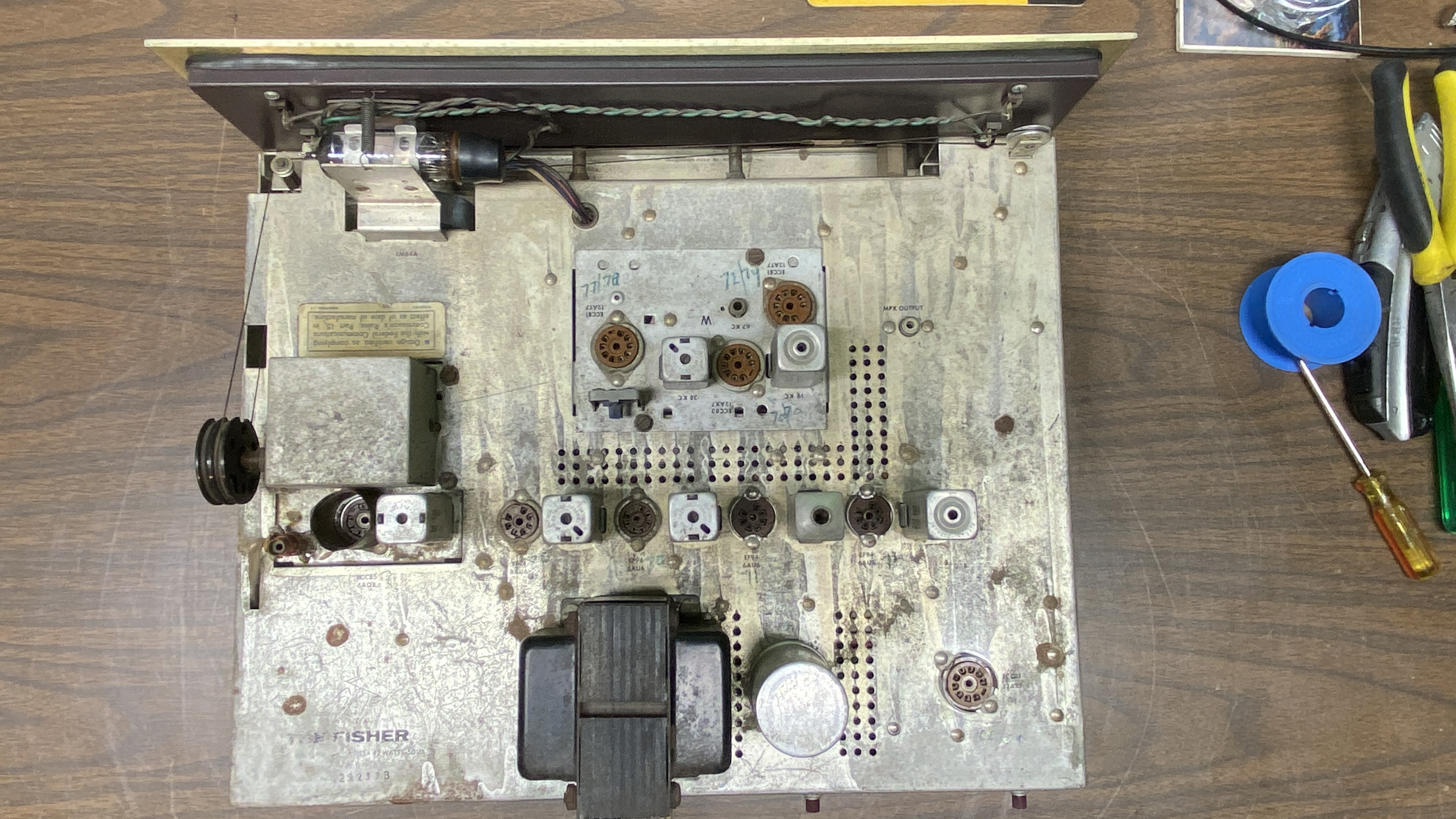 Top view of FM-50-B chassis
Under the chassis, it was evident that someone had attempted to repair the tuner but did a very sloppy job. The 10 uF electrolytic in the ratio detector circuit had been replaced, but the original had been left in place with one of its legs having been lifted, effectively removing it from the circuit. The original four section electrolytic can had been disconnected and four no-name Chinese electrolytics had been connected under the chassis in place of the originals. The original Siemens selenium bridge rectifier was still in place, which is never a good thing since these can fail at any time – and in fact many have already failed by now. Finally, there were two brown “dog turd” capacitors in the audio preamp circuit which had not been replaced.
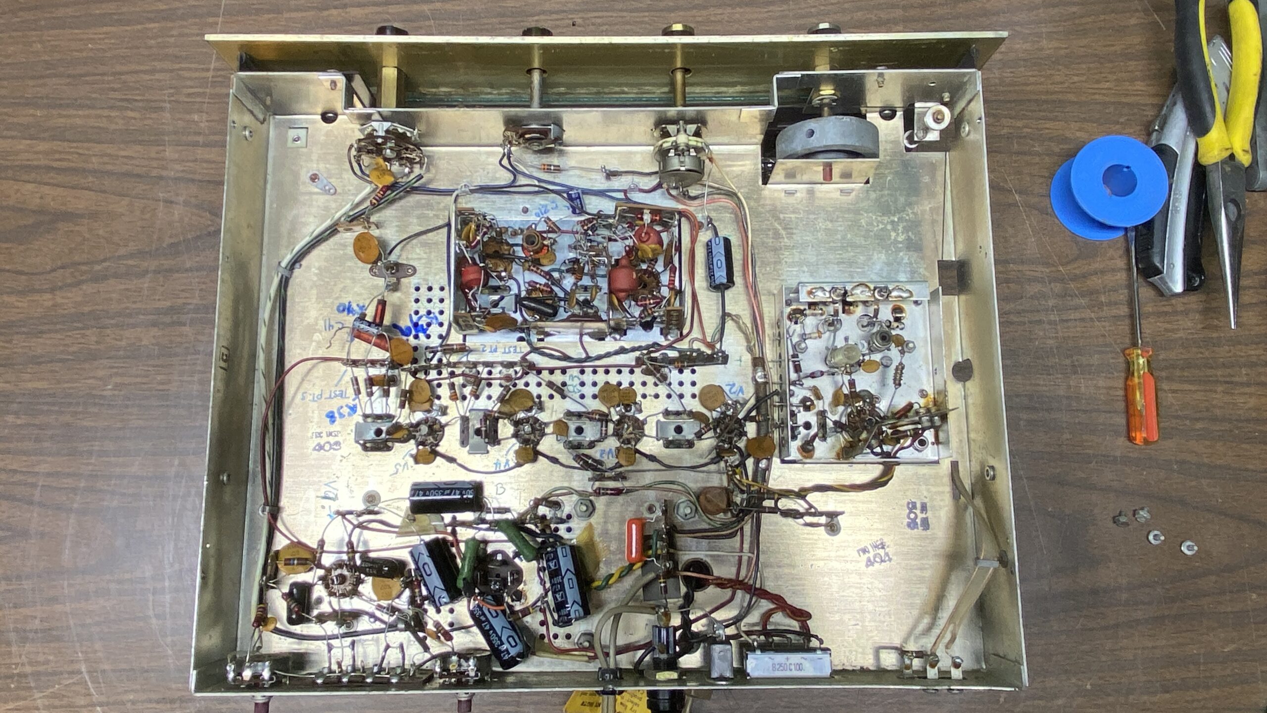 FM-50-B, under-chassis view
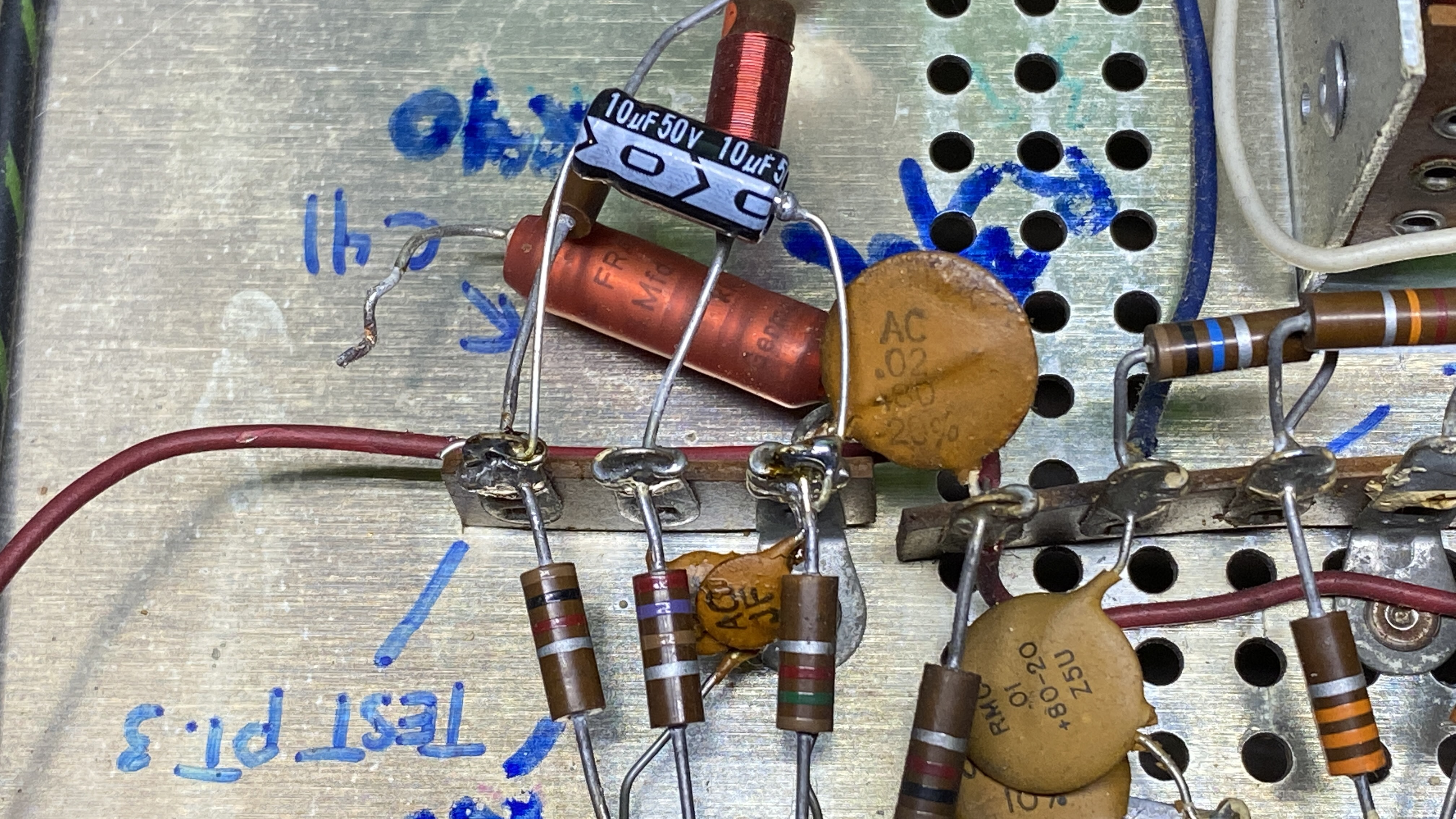 Electrolytic in FM-50-B’s ratio detector circuit
Original multi-section electrolytic had been replaced by four separate electrolytics.
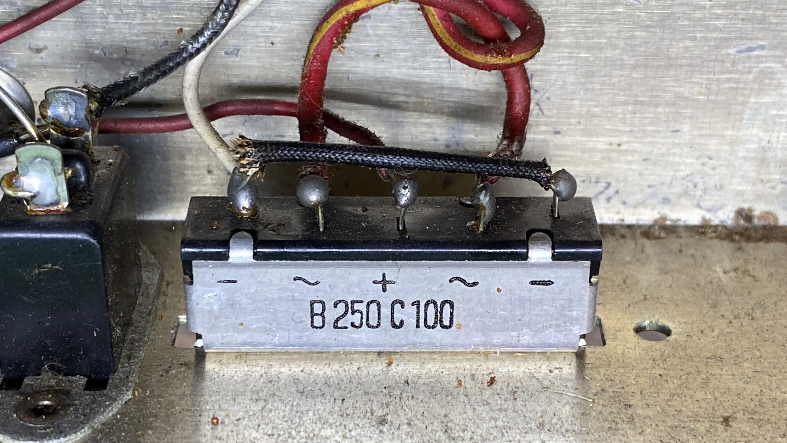 Original Siemens bridge rectifier was still in place.
Two original brown “dog turd” capacitors had never been replaced.
It was Saturday afternoon. The challenge was on. Could I get this tuner running before Monday?
I began by removing the newer 10 uF electrolytic in the ratio detector circuit, and also completely removing the original Frako electrolytic, installing one of my new 10 uF electrolytics in its place.
Next came removal of the two brown “dog turd” capacitors. These were replaced with new metalized polypropylene capacitors which somewhat resemble the original “dog turds”.
The next job was to get rid of the mess that was the four Chinese electrolytics mounted under the chassis in place of the original four-section electrolytic can. This is always the hardest part of any Fisher tuner restoration, and takes the most time. I carefully removed the original twist-lok can from the chassis. Then I cut it open at the bottom by cutting away the flange at the very bottom of the can. I opened the can up, removed everything, and cleaned the can out. This can was then restuffed with four new United Chemicon 47 uF 400V pencil electrolytics, small enough to easily fit inside the can. Once restuffed, the can was reinstalled on the chassis and all of the terminals were wired up as had been done originally.
I also replaced the single 22 uF axial electrolytic under the chassis with a new Nichicon axial electrolytic. I generally only use Nichicon, Panasonic, or United Chemicon electrolytics, avoiding no-name Chinese electrolytic capacitors.
With the work complete under the chassis, it was now time to turn my attention to some of the tuner’s cosmetic issues.
I had mentioned previously that both the front panel and dial scale had issues. I was very fortunate in that I happened to have an excellent FM-50-B front panel as well as an excellent glass dial scale on hand, which I had purchased a few years back along with some other FM-50-B parts for the other FM-50-B I own. The panel and glass were not needed at the time, so it was good that I had them on hand for this project.
Better front panel and dial scale for the FM-50-B
The good front panel was from a newer FM-50-B since it was not gold anodized aluminum; instead, it is champagne-toned aluminum. I prefer the look of the brass-toned aluminum, but when faced with a choice of a poor condition brass-toned panel or an excellent champagne panel, the champagne panel wins.
I carefully cleaned the good dial scale. But before I mounted it in place, I noticed that this FM-50-B had been built with dial lamp sockets made for the skinny festoon lamps as used in Fisher tuners made between 1959 and 1961. The package of parts which had included the nice front panel and dial glass also included the metal panel to which the dial glass mounts. And…that metal panel also had the festoon sockets. These festoon sockets were made for the newer, wider type of festoon lamps.
Today’s fuse lamps will fit the newer style of Fisher festoon lamps. However, the older style is about 1-2 mm smaller in diameter and modern fuse lamps will not fit those sockets.
It took some time to do this, but I replaced all four of the festoon sockets with the newer style sockets so I could use new LED fuse lamps in this tuner. Once the sockets were replaced, I installed the good dial scale, followed by the good champagne front panel.
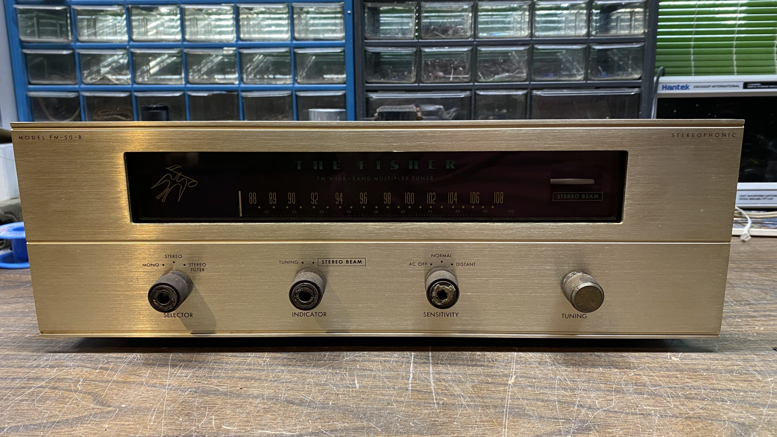 The FM-50-B as it appeared after replacement of front panel, dial glass, and knobs.
While looking for something else recently, I had found four of the proper style Fisher knobs for this tuner. Three need the brass knob caps, but since these are being reproduced, it is simply a matter of my ordering some and gluing them to the knobs.
Finally, late Sunday afternoon, it was ready to try out. I found some of the tubes I needed from my tube stash, but had to borrow the four IF tubes from my other FM-50-B. I connected the audio outputs to my workbench Lepai amplifier, connected a piece of wire to one of the FM antenna terminals, plugged in the FM-50-B and turned it on.
It worked!
I noticed that the contacts of the third IF tube socket will require cleaning and tightening of the contacts, and the EM84A’s display was quite dim. The tuner will also require an alignment.
But the important thing is, it is working. And it is working in Living Stereo! The weekend recap had been successful. It was a good feeling to accomplish my goal of restoring this FM-50-B tuner in a single weekend!