
Right after Christmas Day, I decided to start on another project, very similar to the Philco 41-KR I had stopped working on only days before.
Some background: For the 1942 selling season, Philco offered a choice of two radios designed to sit on top of their Philco refrigerators. The higher end model, the 42-KR5, included a clock in addition to the five tube radio. The other choice was this one – the 42-KR3, which had no clock.
I had acquired this little set in August 2021. For some strange reason, I enjoy working on these little Transitone sets. Perhaps it is because I take them down to bare chassis and then completely rebuild them from scratch. In order to make the radio safe to operate, the old dry-rotten rubber insulated wires inside these radios must be replaced, and the best way to do so is to remove all of them and start over with new plastic insulated wire.
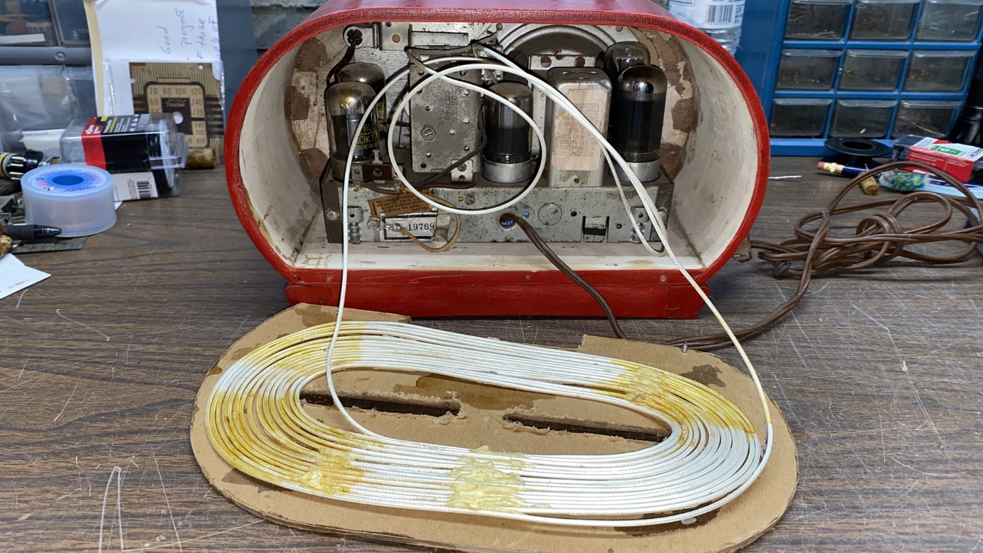
Rear view of the Philco 42-KR3.
This 42-KR3 had clearly seen better days. Its original fiberboard back was gone, having been replaced with a crude homemade back. The original loop antenna was also missing, replaced with an equally crude homemade loop which had been glued to the homemade back.
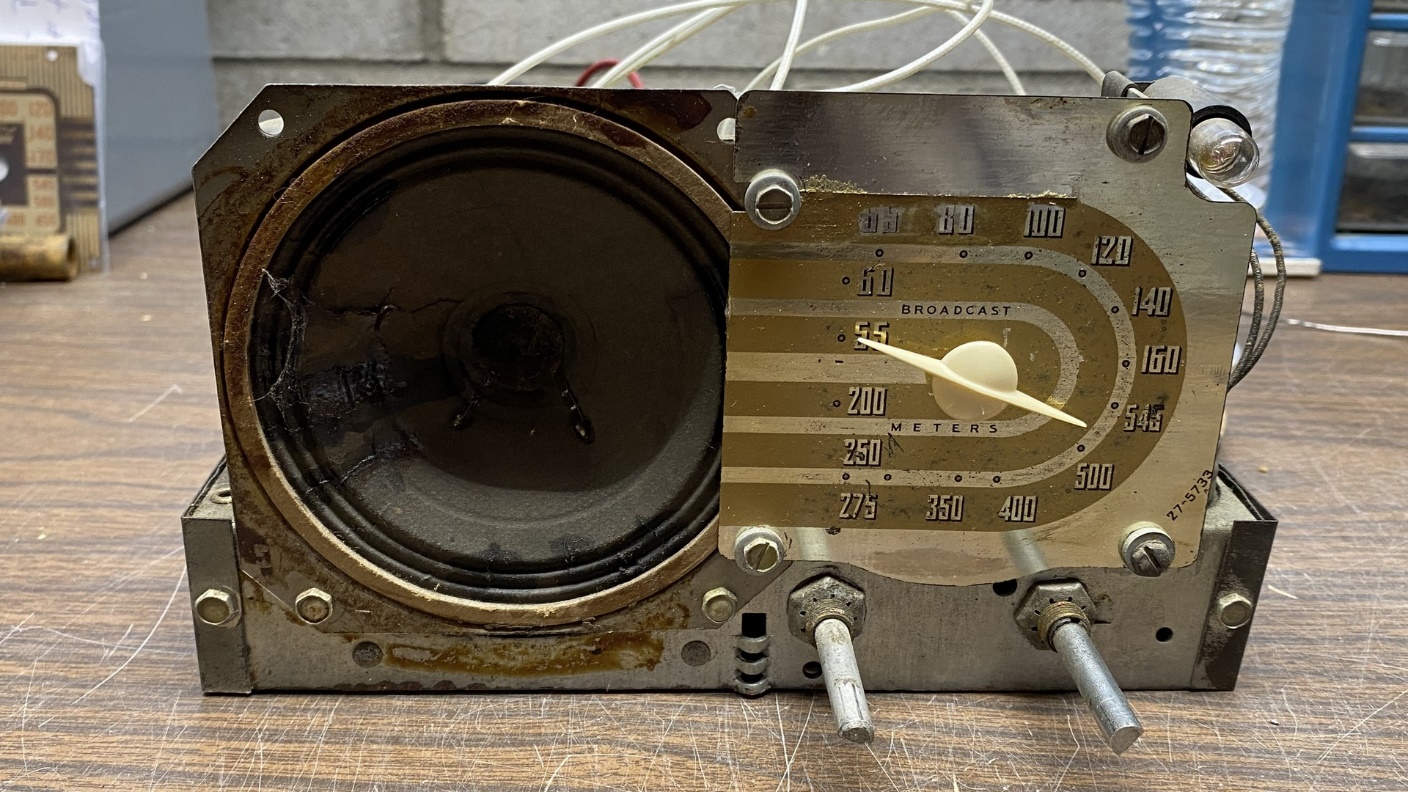
A front view of the 42-KR3 chassis.
The cabinet had been painted red. This will be another job for paint stripper. I hope to be able to strip and repaint both this cabinet as well as my 41-KR cabinet this spring or early summer.
Overall, the chassis was in good shape, but the dial scale was rough as was the speaker cone.
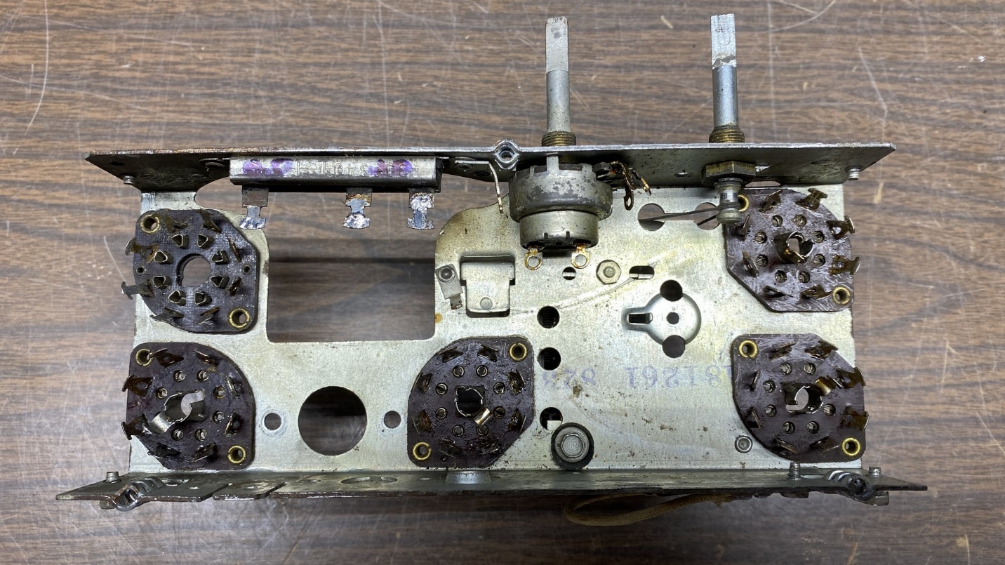
Someone had attempted to repair this radio in the recent past, as may be seen below.
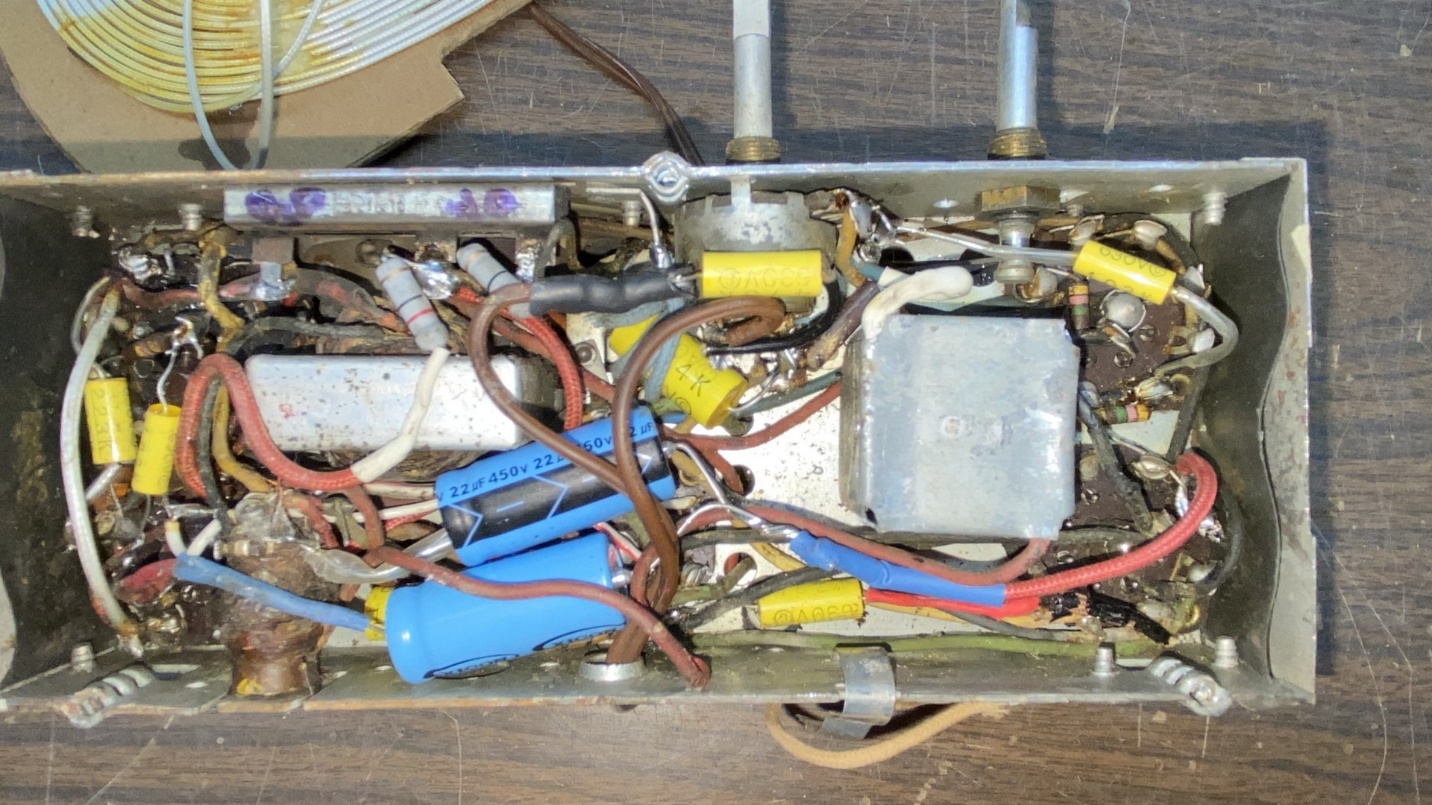
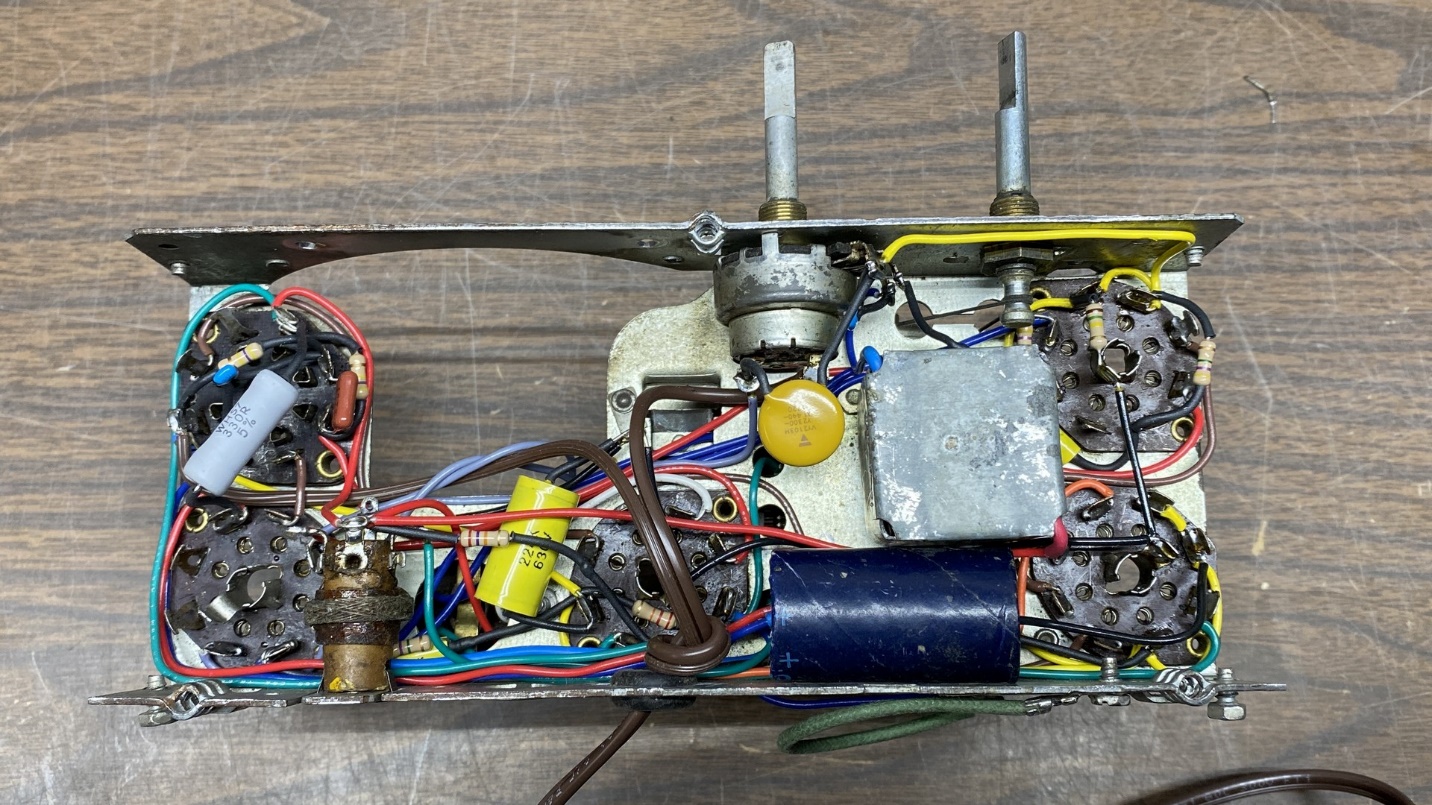
Under-chassis view of the 42-KR3, as received.
I did not bother to try the set out. Instead, I began to make plans to rebuild and slightly modify the set to eliminate the filament dropping resistor, in a similar manner as I had done with my 41-KR.
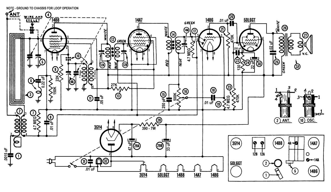
Modified 42-KR3 schematic, showing some changes to the original circuit which I plan to incorporate. Click the image above or click here to see a larger version.
Philco had designed the 42-KR3 with a 50L6GT audio output tube, which I wanted to retain in my new design. As for the other tubes, I decided that I would use a 14B8 in place of the original 7A8; a 14A7 for the 7B7; a 14B6 for the 7C6; and a 35Y4 for the 35Z3. Other than the 35Y4, the tubes were pin for pin replacements for the originals and had similar electrical characteristics but with higher voltage filaments.
The 35Y4 is very similar to the 35Z3 but adds a tapped filament to permit use of a 6.3 volt dial lamp.
Using these tubes will permit me to eliminate the filament dropping resistor as I wished to do.
Underside of the 42-KR3 chassis once everything had been removed.
After spending some time with diagonal cutters and soldering iron, I soon had the chassis completely stripped. All the old rubber-covered wires were discarded.
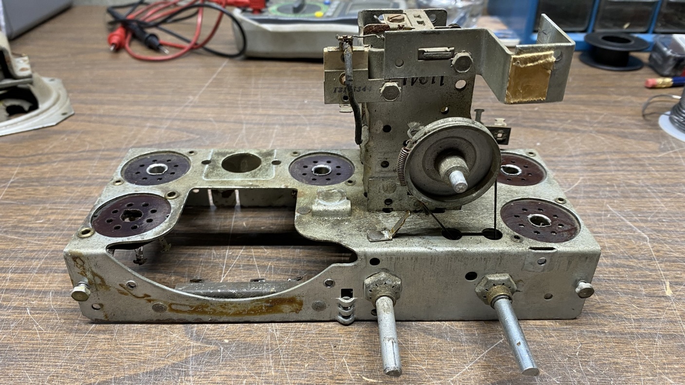
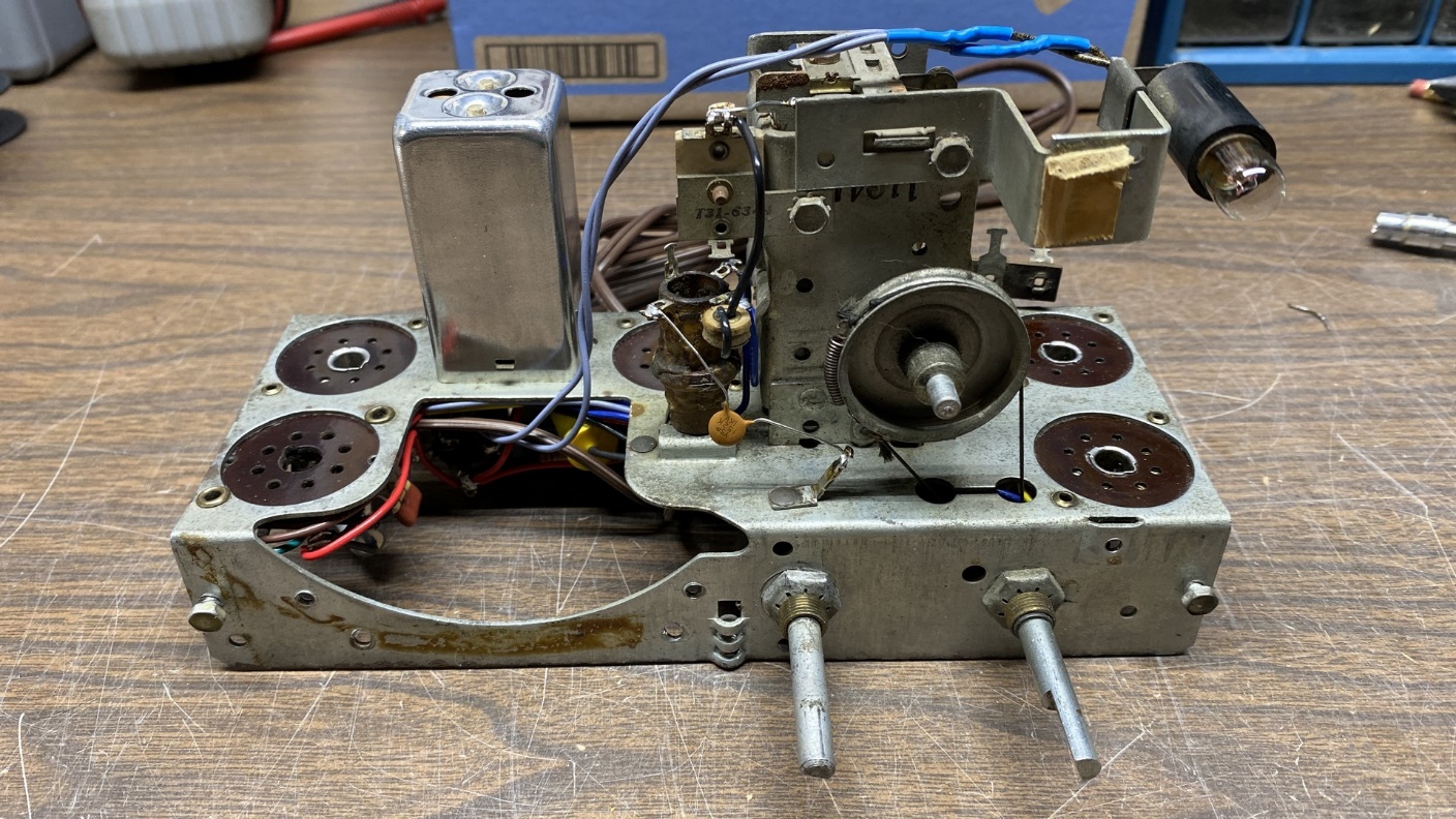
Top view of the bare 42-KR3 chassis.
I had chosen this little radio on purpose. I knew I would be having surgery on January 3, and I would not be able to lift anything heavy for weeks afterward. This is why I chose the 42-KR3 to work on, knowing that after I had surgery and after I recovered enough to return to the workbench, I would have a very lightweight radio waiting for me.
In order to keep this from turning into an extremely long post, let’s take a break for now. Next time, I will show you the original dial scale of this radio and tell you what I decided to do about it. I will also dive into the actual rebuilding of the chassis. Please join me then.
Philco 42-KR3 Chassis Rebuild – Conclusion
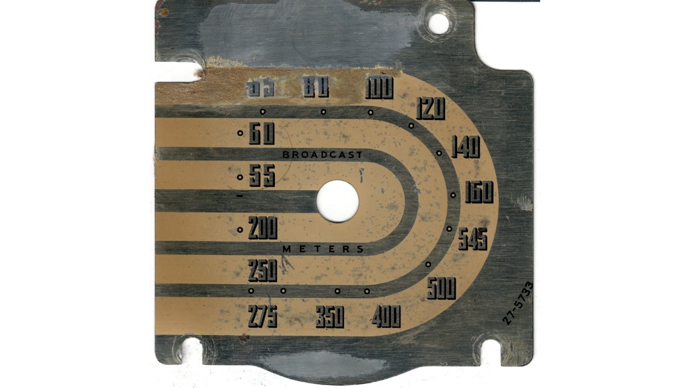
A scan of the 42-KR3’s original dial scale.
I removed and scanned the radio’s dial scale just before I had surgery. You can see above just how rough the original dial was. Replacements are not available. This left me with two choices – use the old rough scale and just live with it, or scan it, attempt to clean up the scan, and print a new one. I chose the latter.
Once I was able to start using my home computer again, I began the slow work of cleaning up this scanned artwork. After a couple weeks of working on it, I finally had something I could use as seen below.
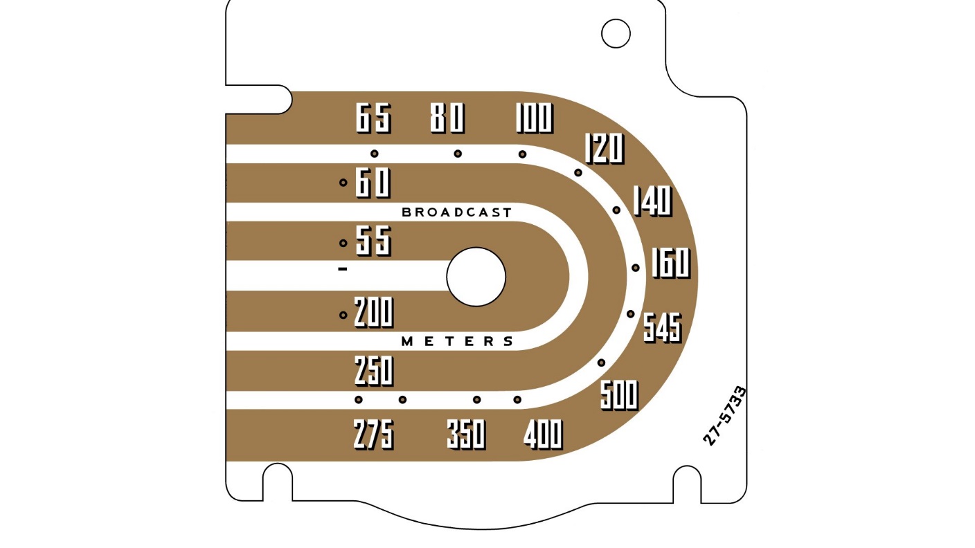
Cleaned-up artwork of the 42-KR3 dial scale.
If you look at the original dial, you can see that it originally had a gold colored background. My plans are to print the cleaned artwork onto a sheet of gold craft paper to create a new dial scale for the radio.
Ah, but I found that my printer is out of yellow toner, Nice. Well, the printing will have to wait a while. There is no rush anyhow; I intended to spray the printed artwork with clear lacquer to protect it, and I can’t spray any lacquer until spring.
Underside view of the 42-KR3 chassis, mostly rebuilt save for the speaker.
By now I felt like returning to the workbench, and I set about rewiring the set. In fact, I became so involved in the work that I did not stop to take any photos until the radio was nearly complete and only needed a speaker.
This chassis now only needs a good speaker to be complete.
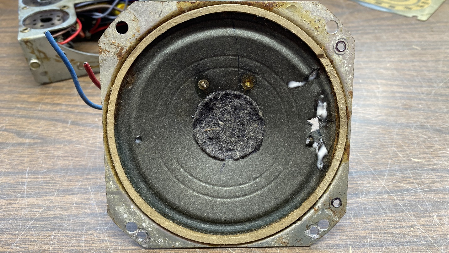
I purchased a rough little All American Five (AA5) Zenith radio with a 4 inch speaker on eBay. I had intended to use its speaker in this radio. However, when the radio arrived, I found that the chassis was not bolted to the cabinet and as a result, it bounced around inside the cabinet a lot on its way here, which is likely what destroyed the speaker cone. Yes, I did get a refund for the unusable radio.
As I could not proceed without a good speaker, I advertised for another 4 inch speaker. Soon, I received a few replies. I decided to hedge my bets and bought three speakers from two of the respondents. They were very cheap which is always a good thing. Besides, I can use the others in future Transitone projects should I choose to do so.
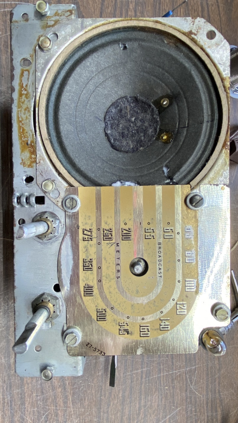
A couple days later, the first speaker arrived. I immediately set to work drilling new mounting holes for it since the speakers in these Transitone radio chassis used off-center mounting holes. Once the holes were drilled, I temporarily mounted the speaker to the chassis as shown below, temporarily attached the old dial scale, and marked off where two more holes needed to be drilled to hold the dial scale in place.
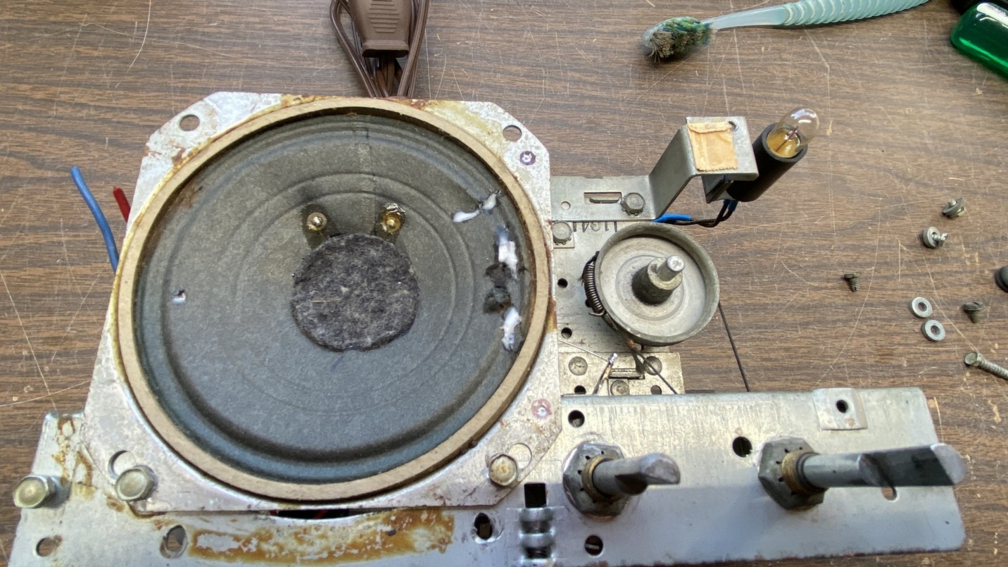
The replacement speaker is temporarily mounted to the chassis to determine where the two dial scale mounting holes needed to be drilled.
Once the marks had been made, the speaker was removed and the holes carefully drilled. After drilling the holes, I tapped the two holes for a 6-32 machine screw thread as the original speaker had for mounting the dial scale in place.
The replacement speaker, with four new holes drilled and two of them tapped for 6-32 threads, is ready to be permanently mounted on the 42-KR3 chassis.
My next move was to permanently install the replacement speaker on the chassis. Once this was done, I attached the dial scale in place for the time being.
As soon as I am able to print a replacement dial scale, I will install it over the top of the original. The original thin metal will provide stability to the paper replacement dial scale.
Both speaker and dial scale are now in place on the chassis.
I then attached longer wires to the output transformer leads and ran these to the 50L6GT plate and screen grid terminals.
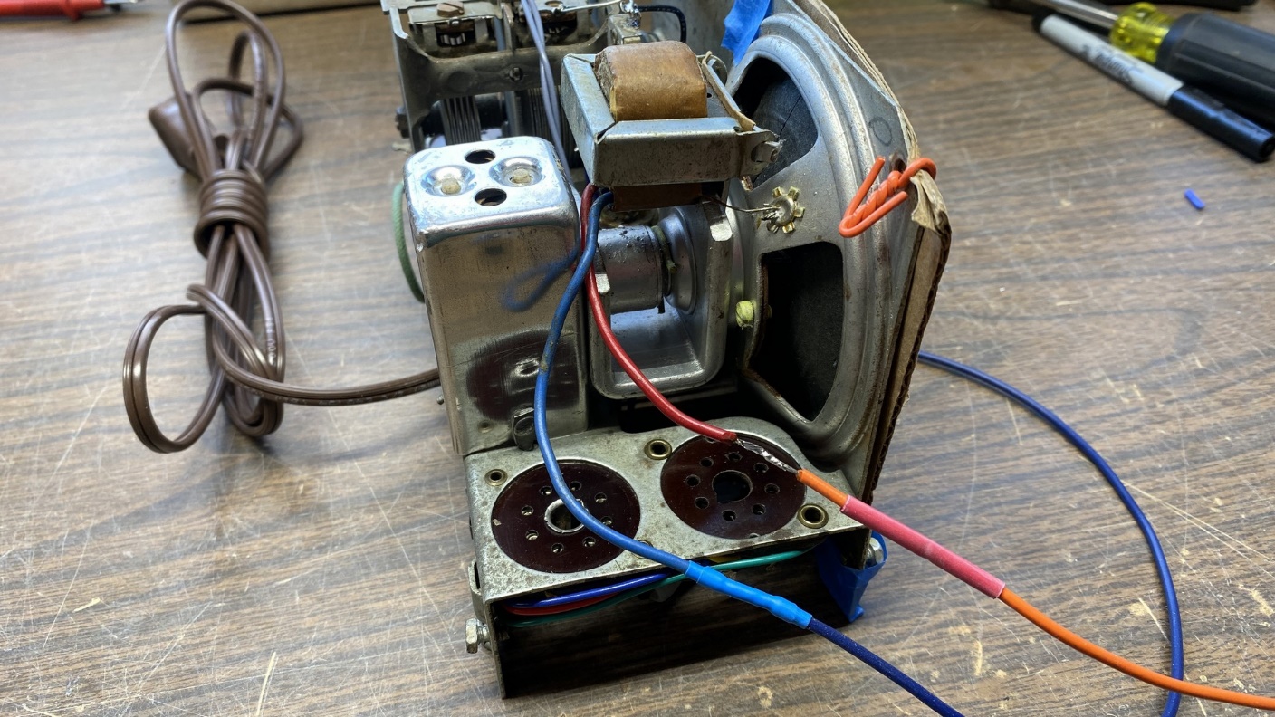
Two pieces of heat shrink tubing were placed over each of the two joints where the output transformer leads had to be lengthened. You can see the output transformer is now on top of the chassis.
The radio was now ready to try out. I attached a red pointer temporarily, and then connected an old loop antenna from a dead 1950s All American Five (AA5) radio. I also installed all five tubes.
Plugging the set in and turning it on, I waited about thirty seconds until I began to hear static noises in the speaker.
I tuned the set across the AM band. It was motorboating at the very low end of the dial (around 550 kc) but otherwise, seemed to be doing well. It did not pick up very many stations. But then again, I did not really expect it to. Where I live, there are very few strong AM signals and it takes a powerful AM receiver with several tubes, connected to my outdoor longwire antenna, to bring in the weak, distant signals in the daytime.
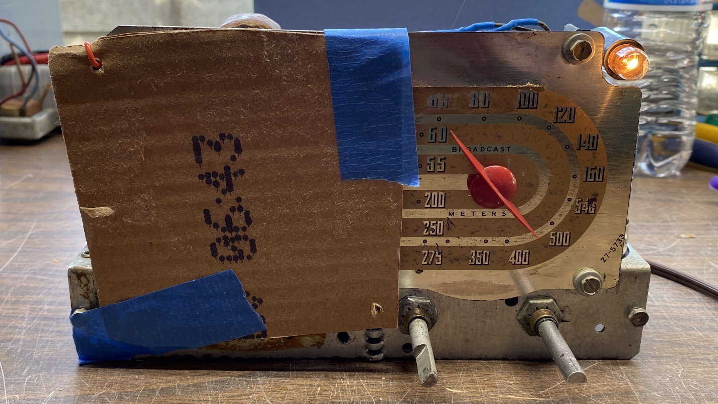
The completed 42-KR3 chassis is put through its paces. The cardboard was left over the speaker to protect the cone.
Following a quick alignment, the little radio seemed to be playing to the best of its ability.
And that concludes the chassis repair of this Philco 42-KR3. When warm weather returns, I hope to be able to strip and refinish its cabinet and decide on a permanent solution to its loop antenna. Yes, and by then I will be ready to print a new dial scale for it.