I left you last time at the point where I had removed the 37-116 oscillator switch assembly from the trimmer condenser unit. At that point, some wires still needed to be unsoldered from the switch assembly.
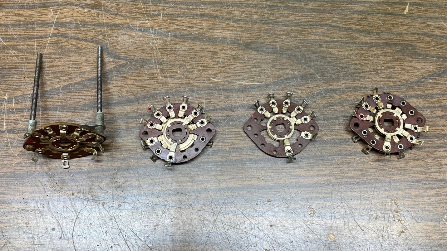
When I resumed working on this, the first thing I did was to unsolder and remove those remaining wires. Next, the switch assembly itself was disassembled, leaving the individual switch wafers.
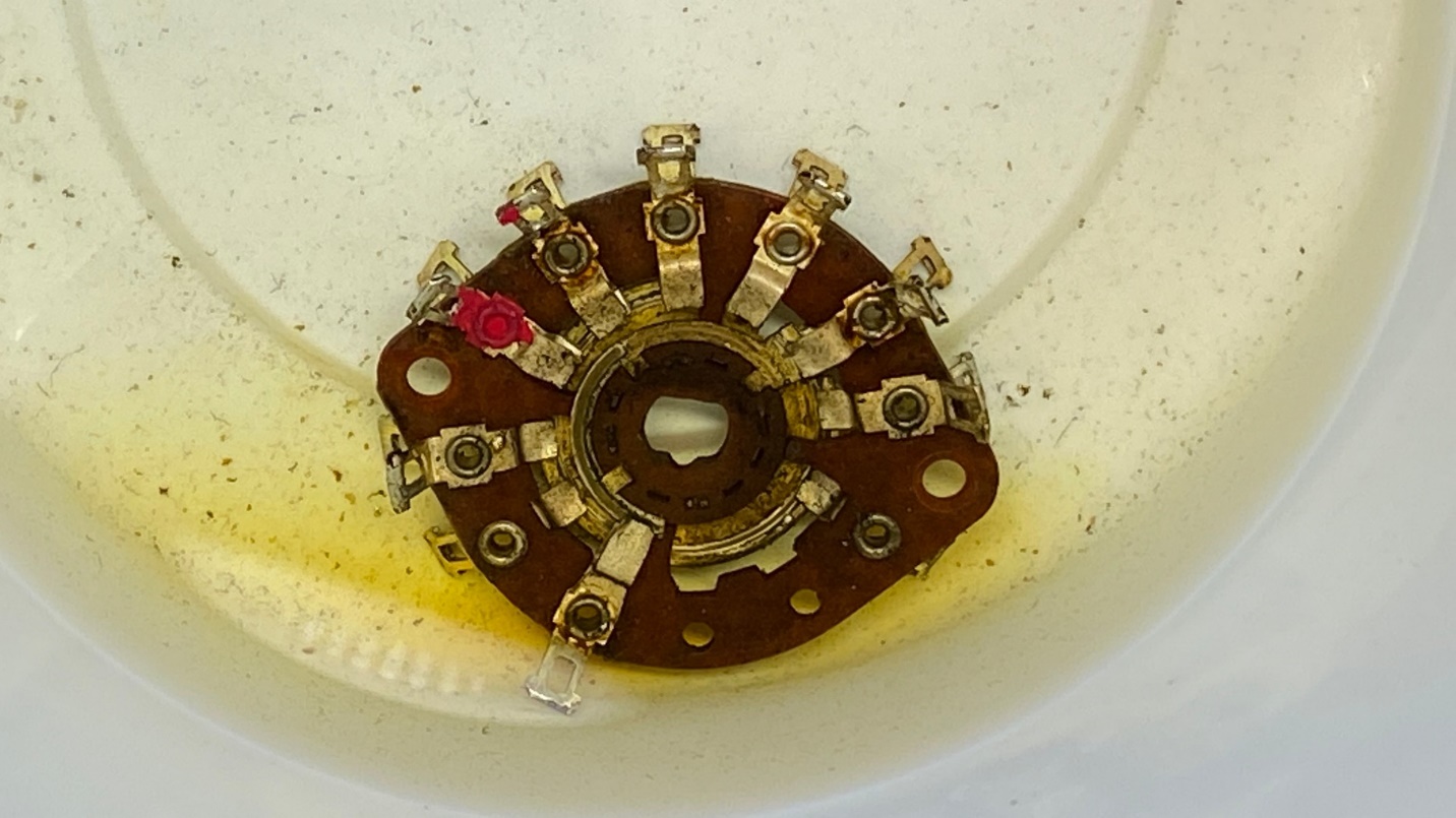
I cleaned each switch wafer with 99% isopropyl alcohol. You can see in the image above that the amount of dirt and grime on each wafer turned the alcohol a light brown. It left the switch contacts nice and bright, though.
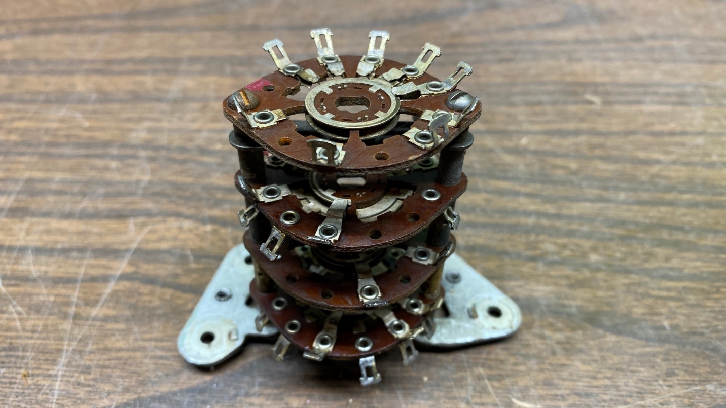
Next came reassembly of the switch wafers into a complete switch assembly. Having carefully kept track of which wafer went in what order, this was not that difficult to do.
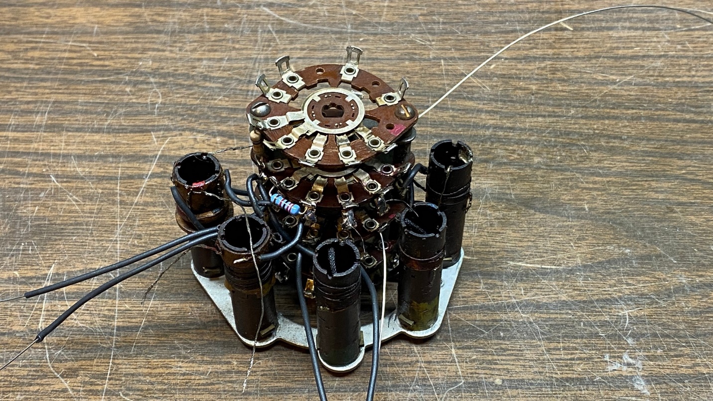
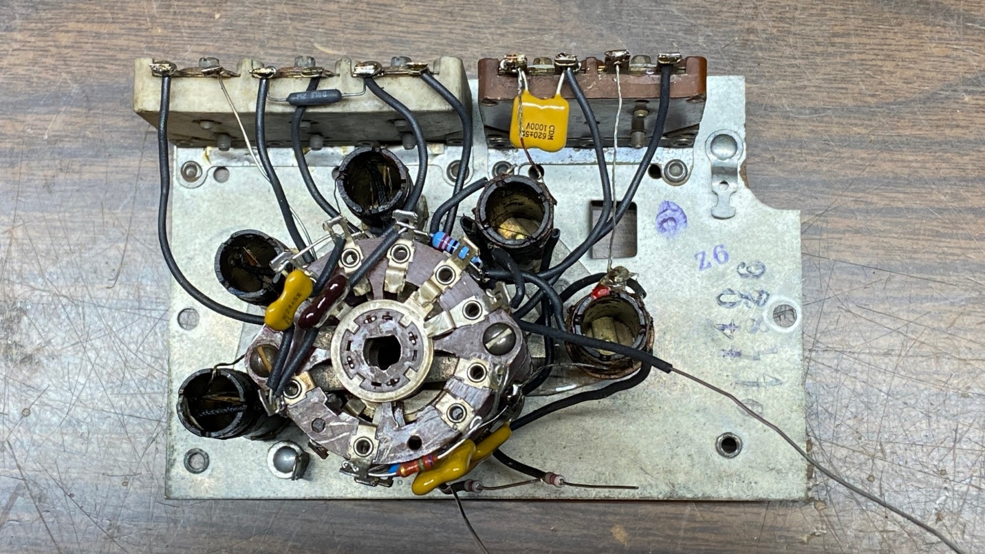
Before long, the assembly was back together again and ready for reinstallation of the coils, wires, and other components.
I began reinstalling the coils, beginning with the Band 1 oscillator coil. This was slow, tedious work. The drawing I had made previously showing how things connect between switch wafers for this section (see Part 6 for details) was a big help.
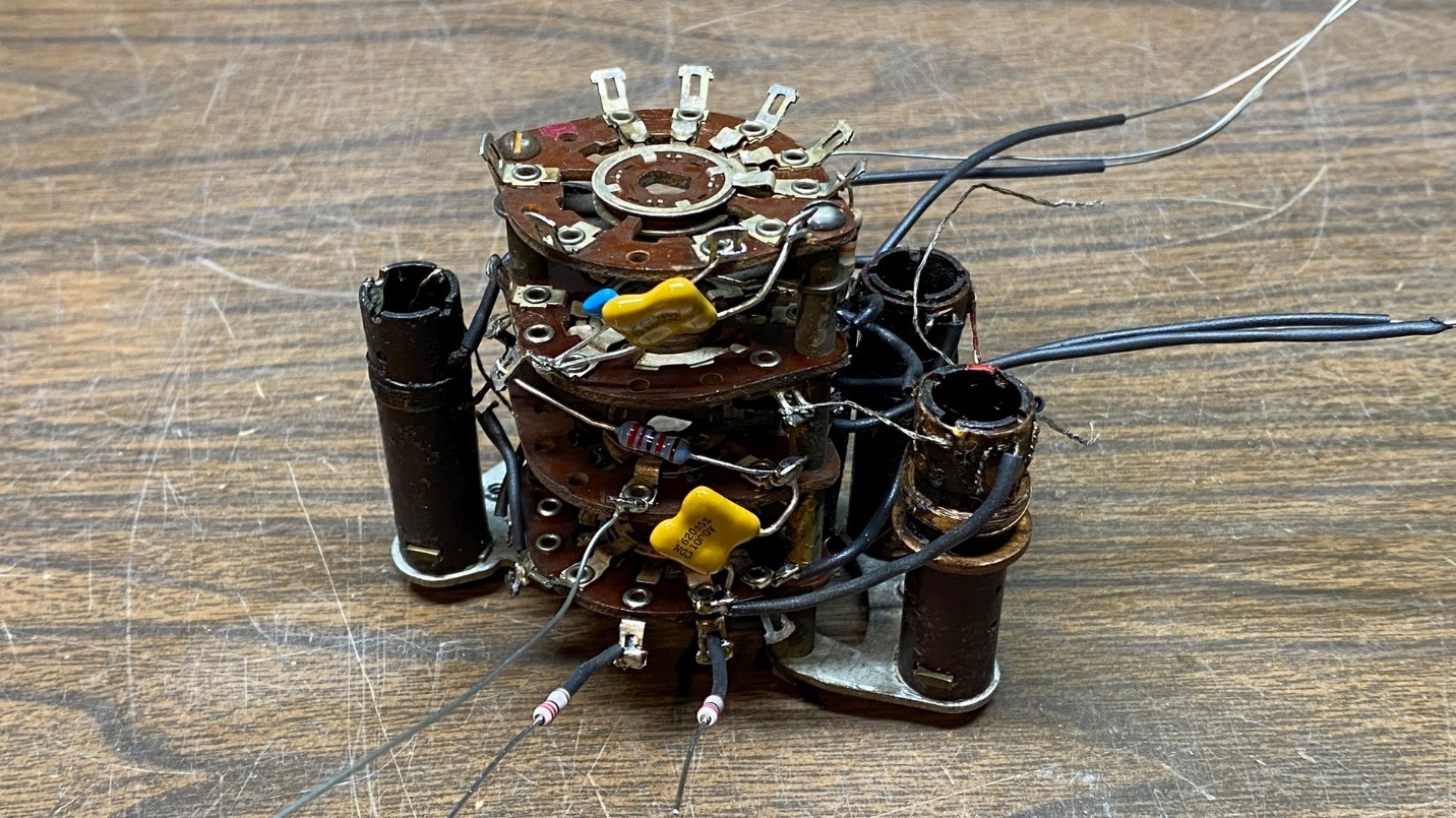
After some more slow, careful work, all five coils were back in place. I made sure each coil had good continuity before, and again after, it was mounted in place.
Next came the attachment and soldering of more wires, as well as some resistors and capacitors.
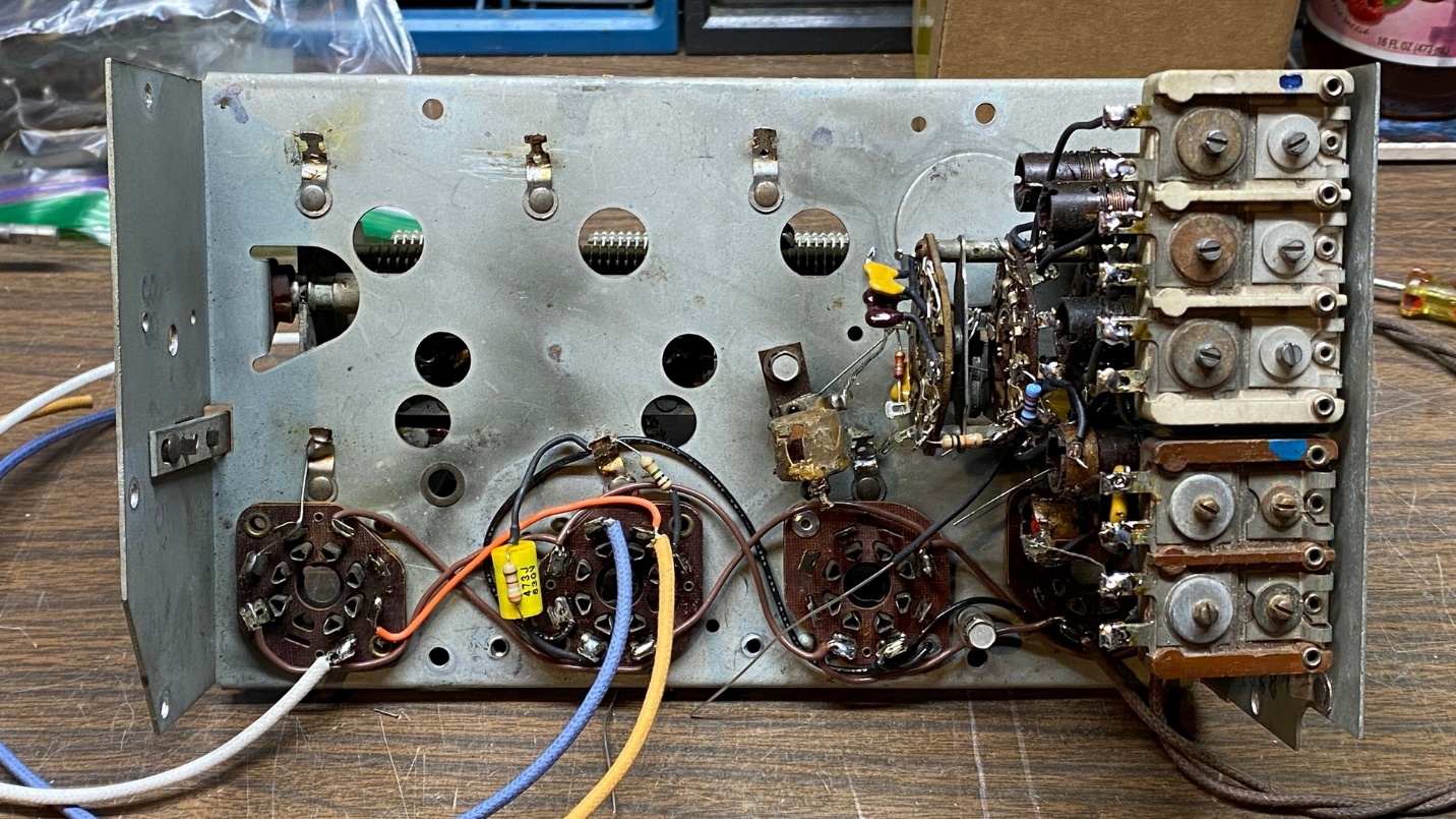
Eventually, I reached a point where I felt it was ready to reattach to the part with the trimmer condensers. Unfortunately, here is where I ran into some trouble. I had failed to document which wire attached to what point on the trimmer condenser assembly. Fortunately for me, I had another 37-116 chassis out in the garage. I brought it in, studied it carefully, and made myself yet another road map or “key” as follows:
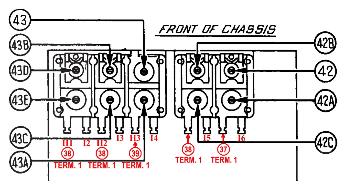
The text in red indicates where each terminal connects.
Armed with this information, I set about to straighten out the wiring of the trimmer condensers. I had managed to wire every one wrong, so every wire had to be removed from the trimmer condenser assembly and redone.
As I did all of this, I managed to break a coil wire. It was the Terminal 1 wire from part (37), the AM oscillator coil. After panicking for a bit, I calmed down and then managed to repair the coil by carefully adding another wire to it, and sealing the area with hot glue.
A careful check afterward with my multimeter indicated that the repair was successful. At least the coil had good continuity between Terminal 1 and each of the other four wire terminals.
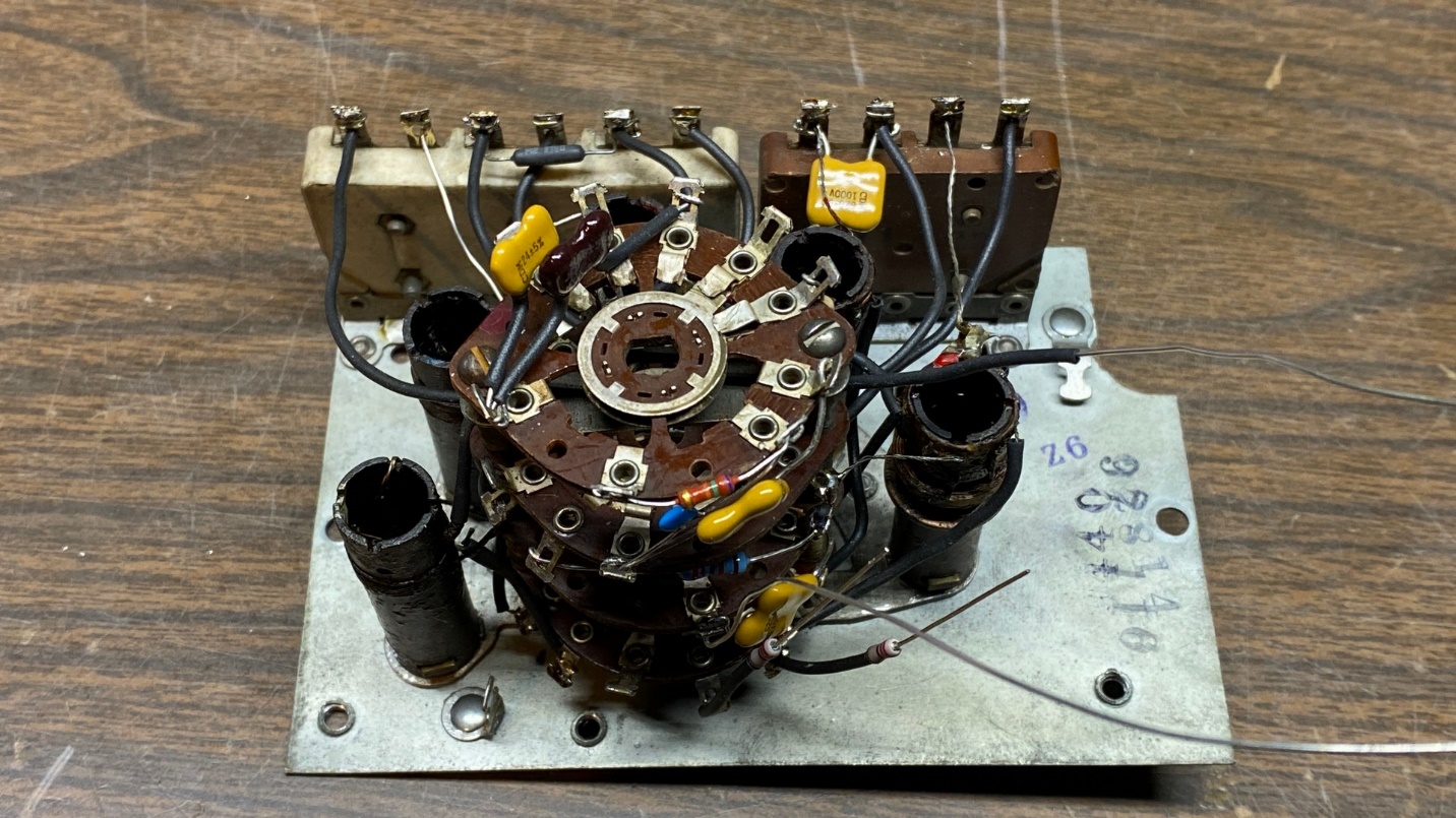
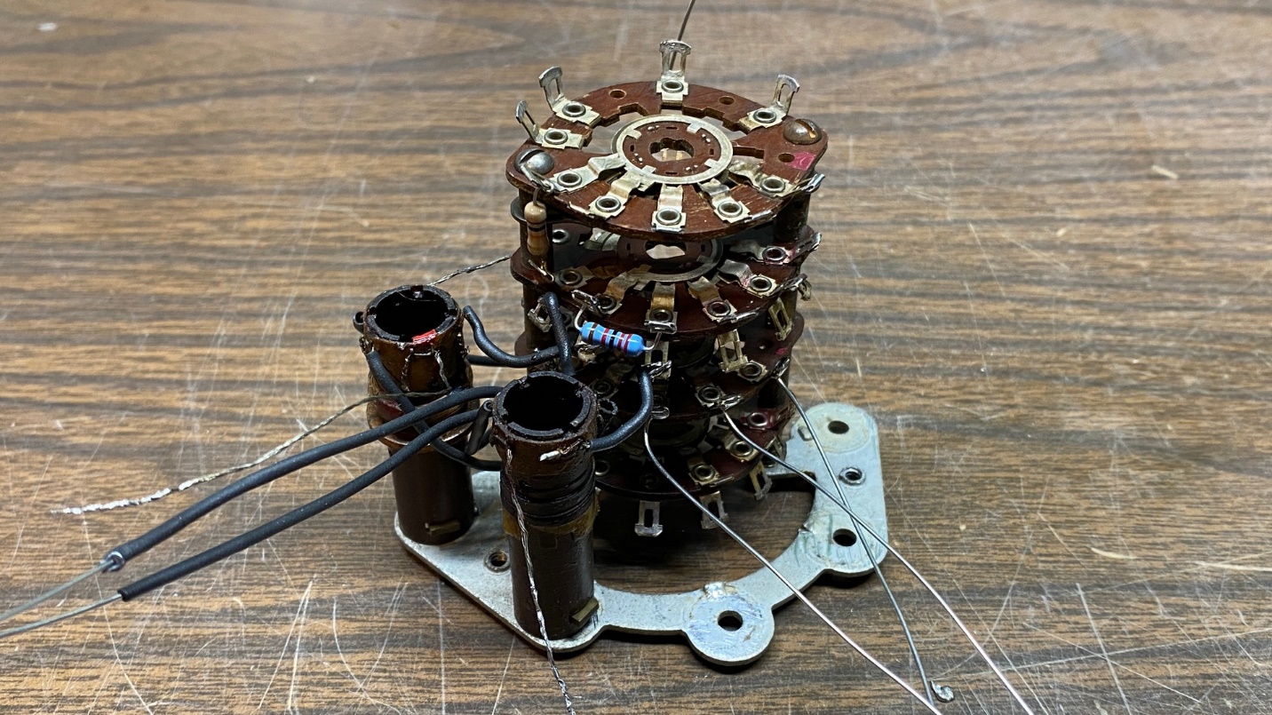
Now that the oscillator section was mostly back together, I continued to add some more components to the switch assembly.
The next thing I did was to reattach the oscillator section to the sub-base. By now I felt that I could finish wiring things up in this section later.
That is far as I am going to go with this for now. It is time for me to begin working on my Christmas radio project – this year, a Fisher FM-200 tuner – and set this aside for a while.
I will resume work on this sometime after the first of the year. Stay tuned as I will finish wiring up the oscillator section, and then add the converter or RF section and then the antenna section, in that order, to the sub-base. Once everything is back together, it will be time to try it out in the 38-690 chassis.