Another power transformer rebuild.
As you may recall in Part 1 of this Philco model 65 rebuild, the first thing I did after opening up the bottom of the chassis (and vacuuming out the stuff left behind by mice) was to take continuity tests of the power transformer windings. The windings all appeared to be ok, so I proceeded with the restoration.
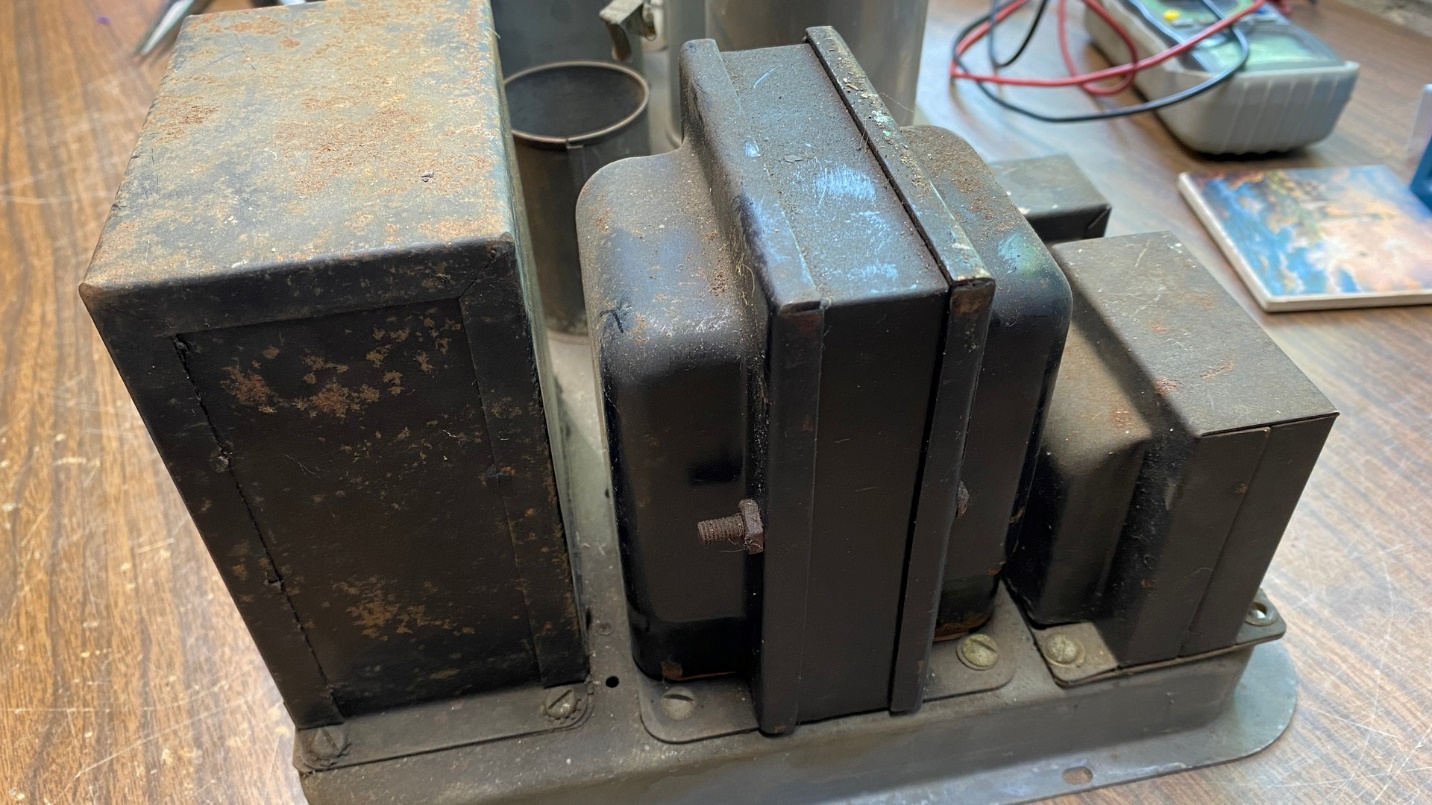
The model 65’s power transformer has 10 solder terminals plus three rubber-covered wires.
As with the Philco model 87 power transformer, the model 65’s transformer has three rubber-covered wires protruding from the bottom of the unit. This rubber insulation has turned to stone after 92 years, so this must be addressed for safety.
Unfortunately, the only way to fix this problem is to remove the transformer from the radio.
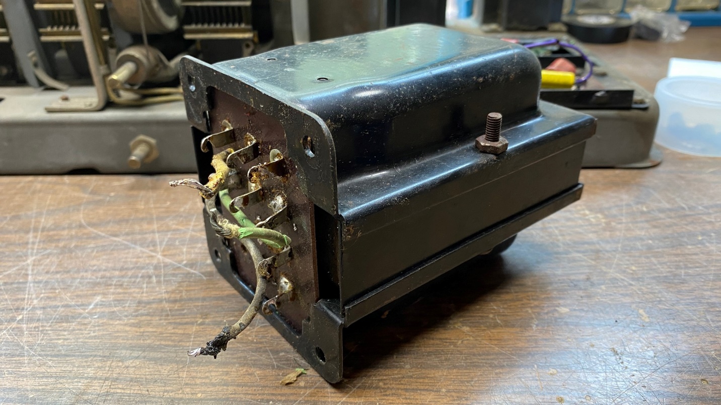
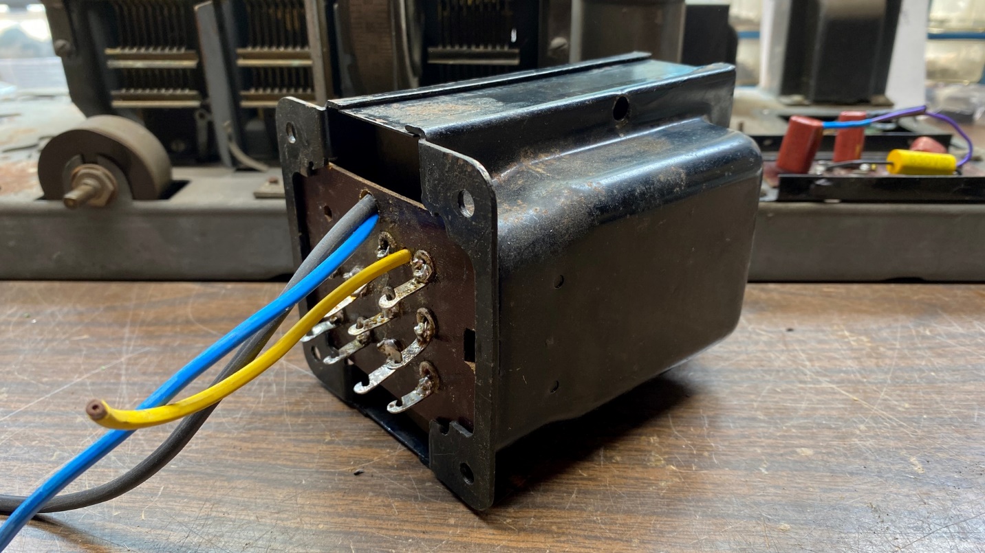
Model 65 power transformer, removed from the chassis.
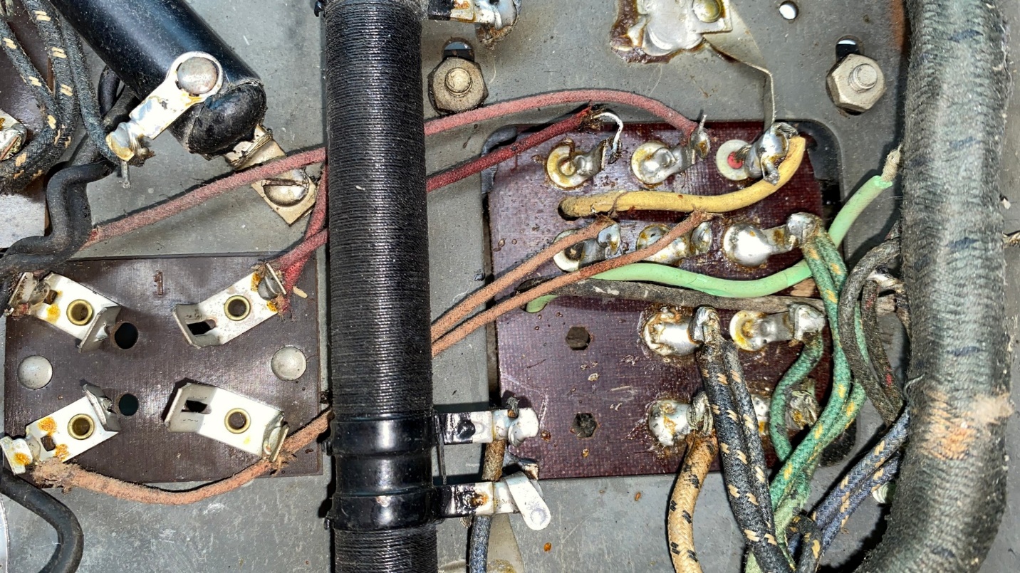
I had to unsolder and carefully remove a multitude of wires from the terminal board at the bottom of the power transformer, plus unsolder and remove the wires which were connected to the primary leads (green and black).
Once all the pertinent wires were disconnected, it was a simple matter of removing four screws and then pulling the transformer from the chassis.
Once I removed the transformer covers or “bells”, I found that several of the internal wires had also been insulated with rubber when the transformer was built. So, I had to remove each wire, one by one, and replace or resleeve every internal wire. This job took an entire afternoon of one day plus an entire morning of another day.
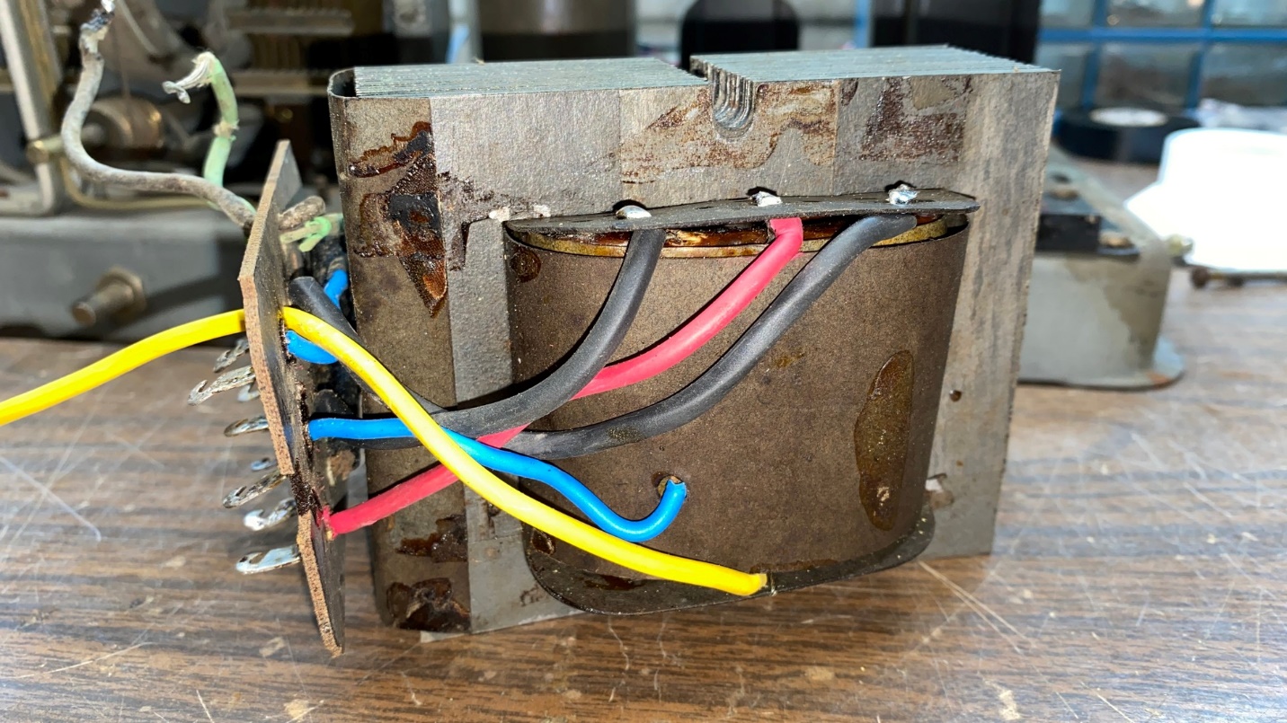
Part of the transformer’s internal wiring has now been replaced or resleeved.
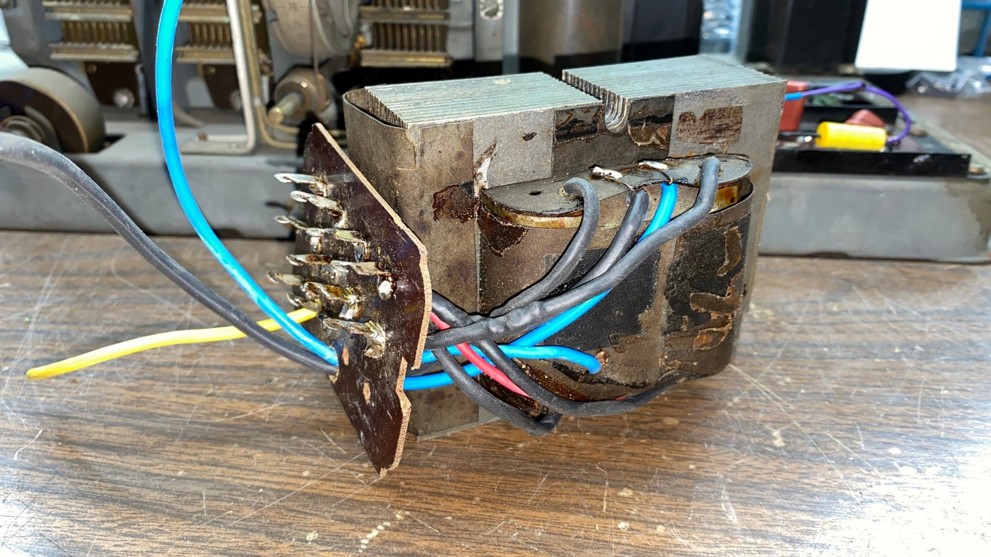
Eventually, all the wires received new insulation. The yellow, green and black wires were replaced with new wires. The new “green” wire has blue heat shrink tubing as I did not have any green heat shrink.
Once all the wires had been resleeved or replaced, it was a simple matter of reattaching the end covers or “bells” and reattaching the two bolts and nuts which hold the transformer together.
A successfully rebuilt transformer, only needing its bolts and nuts to be complete.
I decided to leave the transformer off the chassis until after I had addressed the other issues under the chassis. The chassis is much easier to move around, flip over, etc. without a heavy power transformer attached to it.
In my next post, I will address multiple minor issues under the chassis.