Bad news – and a warning.
At this stage of the game, I was waiting for a parts order from Mouser Electronics which included two resistors – a 68K, 1 watt unit to replace the original 70K, 1 watt, part (34); and a 3900 ohm, 5 watt unit to replace the open 3785 ohm section of the three-section power resistor, part (35).
While I waited for the parts, I decided this was the time to work on the power transformer, part (30). Normally, there is nothing to do to a power transformer; they either work, or they don’t. You always hope they are ok, but sometimes they are not. Keep this thought in mind as I go on.
Once resistor (35) is removed, it is easy to get to the terminals of the power transformer and to remove it from the chassis.
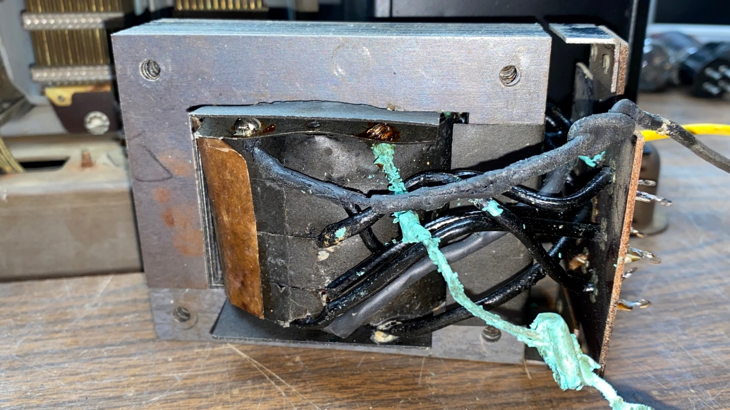
Anyway, the reason I felt the need to remove the power transformer was because, in addition to the 12 solder terminals on the bottom, it also had three wires protruding from the bottom. Those three wires had rubber insulation which, after 92 years had turned to stone. I consider old, dried-out rubber insulation to be a safety hazard. Therefore, I felt it necessary to remove the transformer and address this issue.
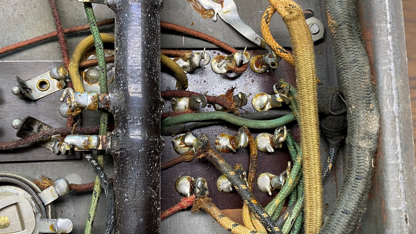
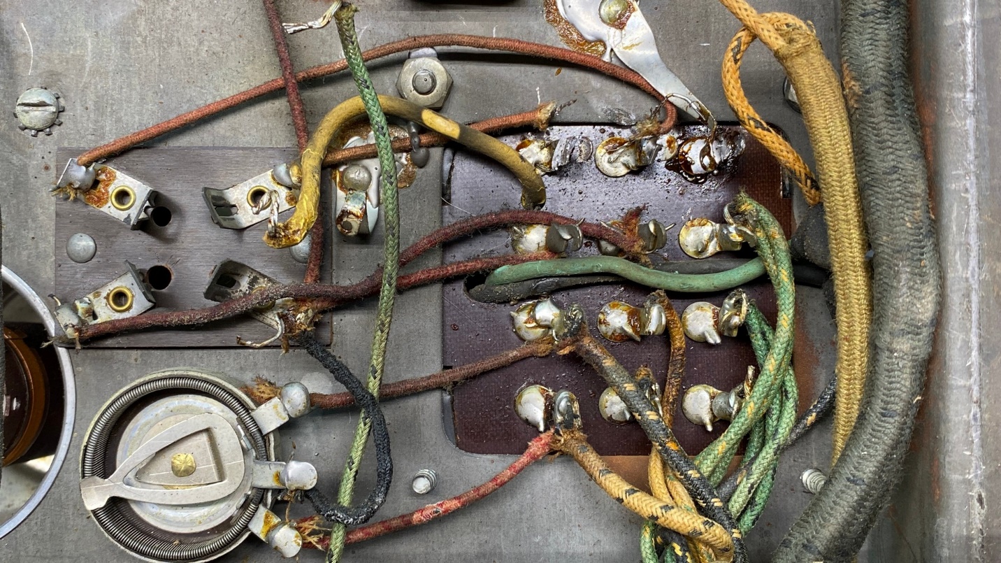
If you are ever faced with a job such as this, take notes and photographs so you are sure of where every wire needs to go when you reinstall the transformer. Also, be very careful when removing the wires from the terminals. Those old wires are 92 years old and very brittle. If you move them too much, the old insulation will break – and then you have another safety hazard. Trust me, you do not want to make a new wiring harness for your 1929 radio unless it is absolutely necessary. So be careful as you remove those wires from their respective terminals.
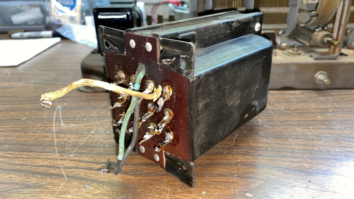
The power transformer, removed from the chassis.
As you can see in the photo above, just touching these old rubber-covered wires causes the insulation to break and crumble, even more so than the equally old cloth-covered wiring which I mentioned previously in this post.
Now that the transformer is out of the radio, it is a simple matter of removing the four screws which hold the transformer together, and then removing the two sides or “bells” as they are commonly known.
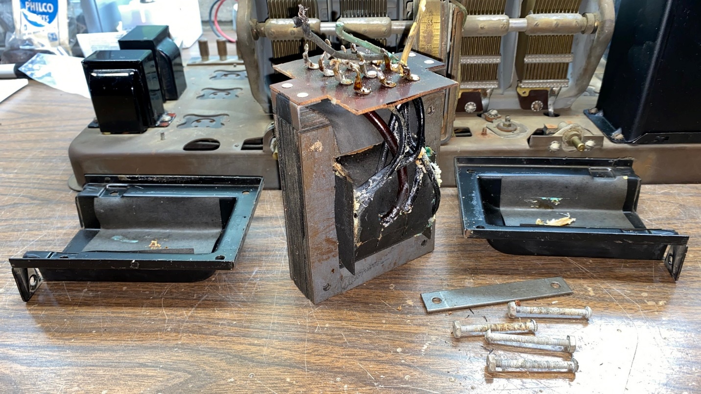
The disassembled power transformer.
Now that I could see the inner wiring of the transformer, it would be a simple matter of making the repairs I wanted to make, and then reassembling the unit.
One of the three rubber-covered wires has been replaced. Two more remain to be replaced as you can see.
I had already decided to replace the three old rubber-covered wires with new wires. As it happened, the original wires were 18 gauge – and I did not have any 18 gauge stranded hookup wire.
I decided to use electrical zip cord instead. This wire is very well insulated and turned out to be a great replacement for the old wires.
I slipped color-coded heat shrink tubing over each replacement wire so they had the same appearance as the original wires. I did not have any green heatshrink tubing so I used blue for the old green wire which turned out well.
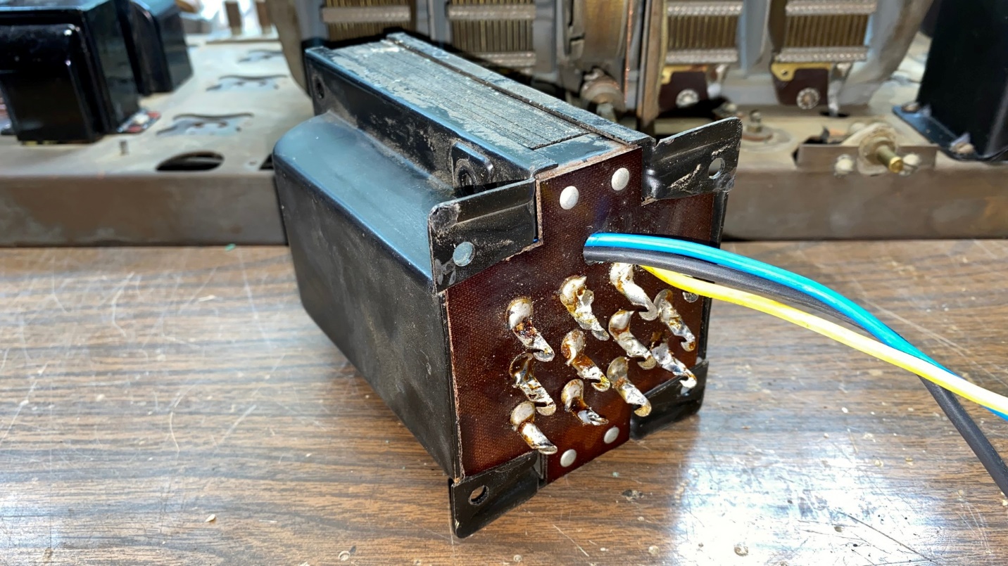
The power transformer with three new wires, replacing the old rubber-covered wires.
Once I was finished, I reassembled the transformer and it looked as it appears above.
And here is where my big mistake occurred.
I decided at this point that I really should check the continuity of the various windings of the transformer. Everything checked out well – except for the high voltage winding! The resistance measurements for that winding, and its associated center tap, were not making any sense. There was a very large discrepancy between the two halves.
Here are the readings:
Total resistance of the high voltage winding, between terminals 1 and 2 – 564 ohms
Resistance between terminals 2 and 3 (half of the winding) – 387 ohms
Resistance between terminals 1 and 3 (the other half of the winding) – 175 ohms
So, a partial short in the half winding between terminals 1 and 3 is indicated. Not good.
Let this be a lesson to you – Always measure the continuity of a power transformer BEFORE you do something like this.
Yes, I knew better than to dive into repairing this transformer before making sure it was ok. I blame the chemotherapy and associated chemo fuzzy thinking (even though it has been more than two months since my last chemo session). As the old country music song goes, “that’s my story and I’m sticking to it.”
So, this was a day wasted. I set the transformer aside and went outside and ran the grass trimmer (“weed eater”) so I would feel like I accomplished something positive.
Of course, this means I am stuck. Nothing further can be done with this chassis unless I can get lucky and find a model 87 power transformer or have one custom made by Heyboer Transformers. Heyboer does great work – I have utilized their services in the past – but their work does not come cheap. Nor should it, really, for custom manufacturing a one-off vintage radio power transformer.
So, my friends, this brings this series of posts on the Philco model 87 to what I hope is only a temporary end. I will continue when I have another power transformer on hand. In the meantime, I will find other subjects to blog about. Thanks for following along.