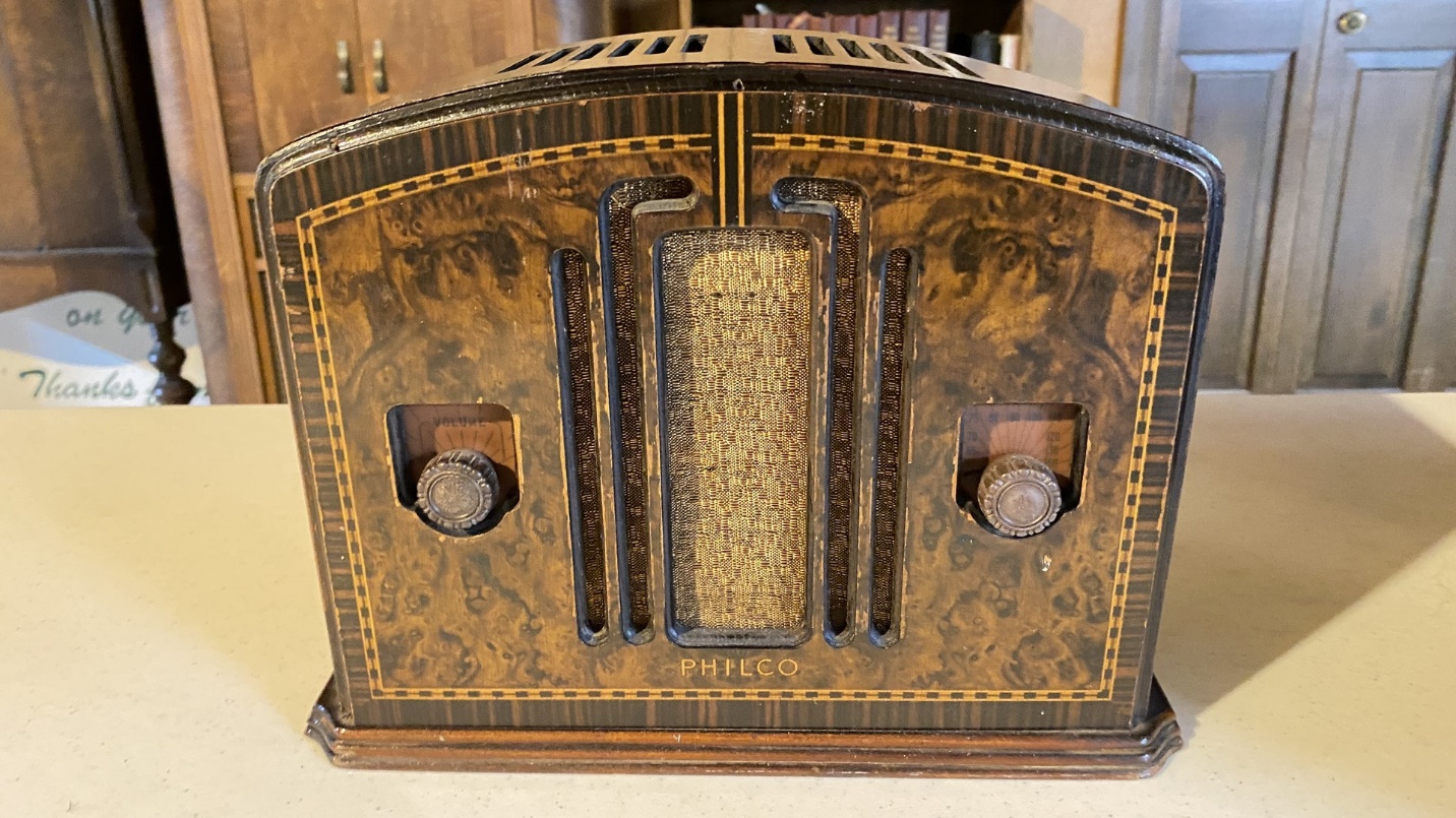
You may recall that a little more than a year ago, I restored a Philco model 54C. Its original cabinet was in very poor shape. A good friend of mine gave me his Philco 59C, suggesting that I use the 59C cabinet to house my restored and modified 54C chassis.
Well, I didn’t like the idea of throwing away what appeared to be a good, restorable 59C chassis, so eventually I found a decent enough 54C cabinet to use with my 54 chassis. (The cabinet only needs a good refinishing and minor veneer repair.) So, once I finished working on my RCA T9-10 radio chassis, I went to work on this 59C.
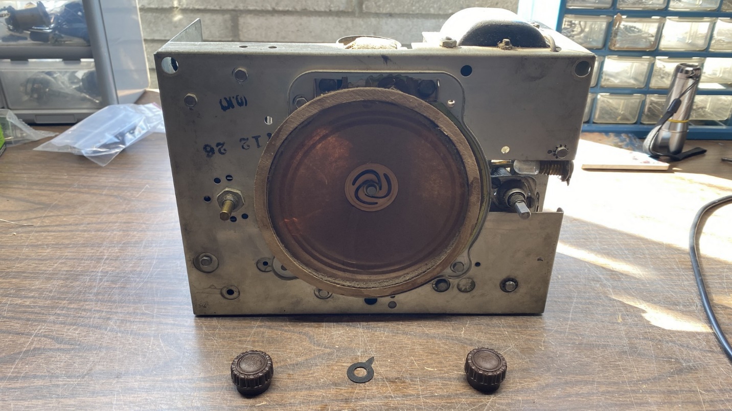
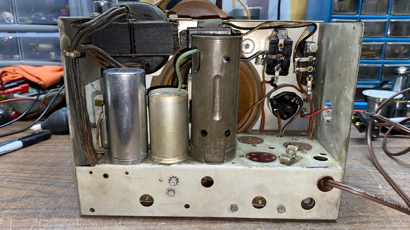
The Philco model 59C chassis.
The chassis is what I call a “four tube gutless wonder.” It uses an autodyne converter circuit and a regenerative IF/detector stage, both using type 77 tubes. A 42 audio output and an 80 rectifier completes the simple four-tube lineup.
This was a fairly quick restoration and, consequently, I did not stop to take very many pictures.
You can find a copy of the Model 59 service data here on the Philcoradio.com website.
Someone had previously worked on the set, only replacing the electrolytic capacitors with new units wired under the chassis. Presumably, the same person removed the original dual electrolytic capacitor can from the top of the chassis, leaving a nice round hole next to the IF transformer. In addition, two paper capacitors had also been added under the chassis.
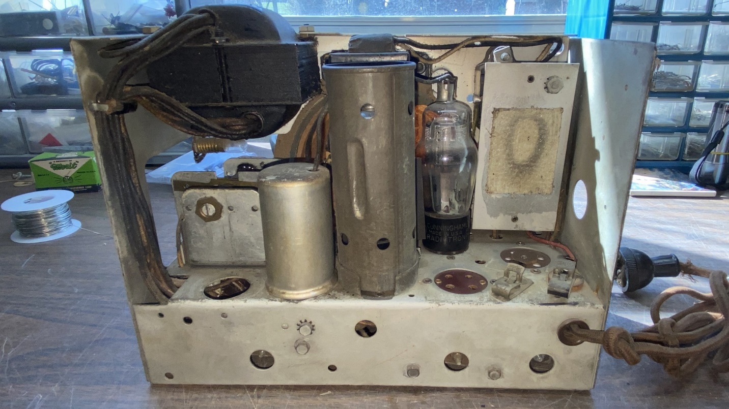
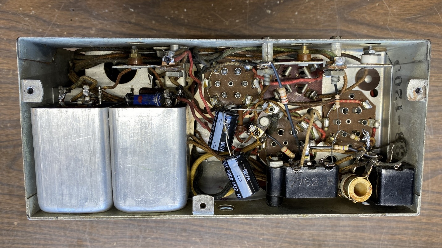
Back view of the 59C chassis.
This radio uses four bakelite block capacitors. These are fairly easy to rebuild. The job is made even easier with the use of handy tools made by Steve Davis, and available at his webpage.
I prefer to remove each bakelite block from the radio, one at a time, and then use Steve’s cutter tool to cut the tiny wires which come out through the holes where the solder terminals are located on the block. I then heat the block with a heat gun for several seconds. After the block is sufficiently heated, the inside of the block may simply be pushed out with Steve’s punching tool by pushing the punching tool through each of the three holes in the top of the block. This will easily push out the “guts” of the block.
Once the old capacitor(s) and waxy potting compound is out of the bakelite block, new components may be installed inside the block. If you are fortunate enough to own a copy of the late Ray Bintliff’s book Philco Condensers and More, you have all the information you need to rebuild almost any bakelite block Philco ever made. Unfortunately, the book is now out of print, but the Antique Radio Classified website still had a few copies available at the time of this writing.
If you do not have Mr. Bintliff’s book, or cannot find a copy of it, you will find useful information on Philco bakelite block condensers here at the Philcoradio.com’s Philco Phorum Library.
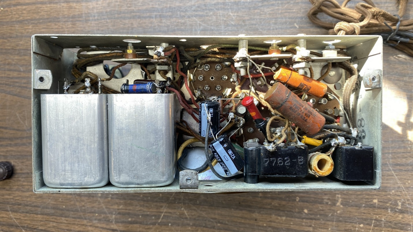
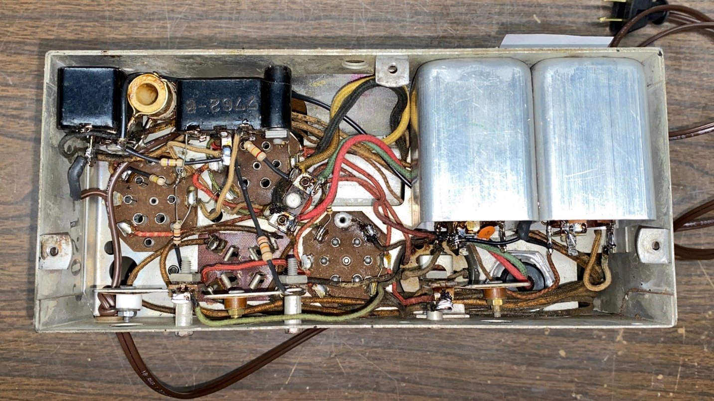
Underside view of the chassis as it appeared before work began on it.
Once I had rebuilt all four of the set’s bakelite blocks, I began to replace resistors. Since the radio has only nine resistors – one of which was the large 325 ohm wirewound bias resistor which did not require replacement – this job did not take very long for the most part.
However, one resistor was hidden inside the radio’s IF transformer can. This necessitated removal of the IF transformer. This was not an easy task, since many of the set’s power transformer wires are routed both above and below the IF transformer mounting bracket. However, by moving trimmer condenser (8) and unsoldering the IF transformer leads, the IF transformer could then be removed. Oh, and let’s not forget the IF transformer has a lead protruding from the top of the IF transformer can, which connects to the grid cap of one of the 77 tubes by using a clip designed for that purpose. This clip must be removed from the lead wire before the IF transformer can be removed from the chassis.
The original Philco design calls for a 4 megohm grid leak, part (14), which is the resistor mounted on top of the IF transformer coil assembly and hidden by the shield can.
Use extreme caution here. One wrong move could render the IF transformer inoperable.
I have found in my experience working on Philco four tube “gutless wonder” sets (models 80, 81, 53, 57, 58, 84, 37-84) that the set’s performance will be improved if part (14) is replaced with a 2 megohm, ½ watt resistor.
The proper way to replace this resistor is to carefully clip the lead wires of the old resistor at the body of the resistor, leaving enough of the old lead wires to solder the new resistor to. Don’t try to remove the lead wires of the old resistor from the coil frame. There are two thin wires which go into one of the IF coil assemblies, and there is a risk of breaking these hair-thin wires if you are not very careful here.
Once I had the new 2 megohm resistor in place, I also installed a new cloth-covered wire through the hole in top of the IF transformer shield. This wire would eventually be soldered to the old 77 tube grid clip.
All bakelite blocks are now rebuilt, and I have begun to replace resistors.
I removed the volume control and opened it up. The AC off-on switch was sprayed with DeoxIT while the control itself was carefully sprayed with a small amount of FaderLube. Once this was done, the control was reinstalled into the radio chassis.
I decided to remove and inspect the antenna and oscillator coil assembly. These two coils were installed in a double coil shield assembly which was mounted under the chassis. Both coils had good continuity. However, I noticed the tell-tale green spots on the outer winding of both coils – a sure sign of corrosion, which is a very common problem with Philco radios made before 1936.
So, I felt I had no choice but to rewind the primaries of both coils. I used 38 gauge magnet wire to carefully rewind these. When complete, the coils were remounted inside the shield assembly.
Now, before I reinstalled the double coil shield assembly and the IF transformer, I decided this would be a perfect time to do something about the missing dual electrolytic can. Fortunately, I had a stud mounting aluminum electrolytic can in my junkbox which used wire leads. I cut the can open, shortened its height by an inch or so, and then restuffed it with two Nichicon electrolytic capacitors – one 8.2 uF and one 4.7 uF unit, both rated at 450 WVDC. I attached new wire leads to these new electrolytics and ran the wires through the hole in the plastic bottom stud.
I then glued the cut end of the electrolytic can back onto the base. When the glue dried, I polished the can with Mothers Mag & Aluminum Polish, and installed the restuffed electrolytic on top of the radio chassis.
With the restuffed electrolytic in place, I then proceeded to reinstall the IF transformer, and then the double coil shield assembly. All these components were then wired back into place in the radio circuitry.
Back view of the mostly restored 59C chassis. Note the red antenna wire sticking out the right side of the chassis.
There is a twisted wire “gimmick”, part (A) on the schematic, which consists of two wires twisted together. This “gimmick” was missing in this 59C. I therefore replicated a “gimmick” with two new plastic coated wires, twisted together in the middle.
I noticed the antenna terminal was very loose, so I drilled out the old rivet and removed the Fahnestock clip and the two insulators. However, when I tried to apply a new pop rivet to put this back together, as luck would have it, I broke one of the insulators! Ugh. I would retrieve another insulator from one of the few junk sets I had left, but would save that job for last.
I then installed a new AC cord and plug. I also replaced the old dial lamp with a new LED lamp.
The set came with only two of its tubes – the two type 77s. One tested good while the other was slightly weak. Both were put back into place – the slightly weak 77 in the converter socket, the good 77 in the regenerative detector socket. Fortunately, I have some spare 42 and 80 tubes, so the radio soon had a complete set of tubes installed.
The 59C chassis has all new capacitors and all new resistors save one.
Finally, it was time to try the radio out.
Running the antenna wire out through a hole in the side of the chassis, I connected my outdoor longwire to the radio’s antenna wire. I plugged the radio in and turned it on.
Soon, I could hear the Spanish language station in nearby Jasper at 990 kc. The radio was working!
I tuned the radio up the AM band. I could pick up a few other stations (there is not a lot that can be heard on AM in my area during the daytime). Needless to say, I was very pleased.
I then gave the radio an alignment. Since this only involves five adjustments, the procedure was quite simple – align the IF at 460 kc, and then adjust the oscillator trimmer and then the antenna trimmer at 1400 kc. Afterward, the regeneration control, which is another trimmer on the back of the chassis, is set with the radio tuned to a station at or near 1300 kc. This all went smoothly.
Finally, it was time to repair the set’s antenna terminal.
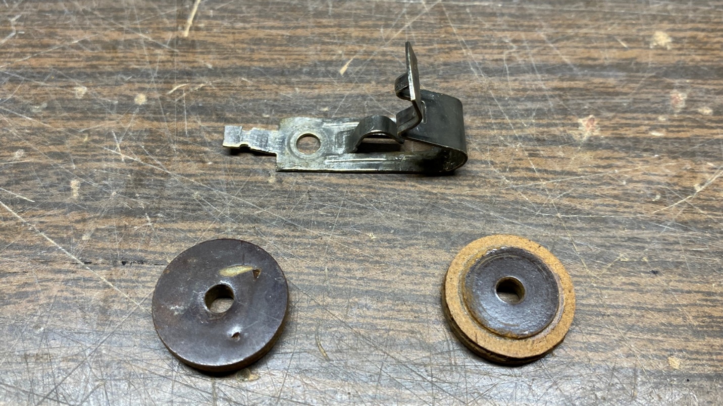
The original Fahnestock antenna clip from the 59C, with phenolic insulators taken from a junked Philco 16 chassis.
I had a very rough and rusty Philco model 16 Code 122 chassis out in the house garage. I removed the needed insulators from its antenna terminal for use in the 59C. While I was at it, I decided to go ahead and junk the entire chassis so I could dispose of it. I’ll write about that in a future Ron’s Radios article.
So, with the insulators on hand from the junked Philco 16 chassis, I prepared to install these along with the Fahnestock antenna clip, into the 59C chassis. I soon noticed that the 59C’s chassis was not as thick as the 16’s chassis was, which makes sense as the 16 chassis is larger and much heavier. The two insulators were machined so that there is a recessed edge around the perimeter of the insulator surface on one side. This makes it possible for both insulators to fit into either side of a hole on the model 16 chassis for the antenna terminal. But since the 59C chassis is thinner, I discovered that the recessed edges of the insulators interfere with one another and the assembly will not stay in place.
I remedied that situation by simply turning the insulator which mounts on the underside of the chassis upside down, so its entire surface is flat. This allowed the assembly to be properly mounted. And this time, I used a 4-40 machine screw, lockwasher, flatwasher, and nut to avoid breaking another insulator with a pop rivet. This worked out perfectly and you may see the results below.
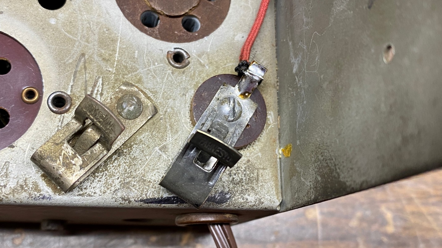
The Fahnestock antenna clip is now reinstalled on the chassis.
The chassis was then returned to its original cabinet. The radio was finished!
So, what about that 54C?
I had mentioned that I had found a better cabinet for it at the beginning of this article. After finding that cabinet, I ended up buying another 54C with a broken cabinet (no top), only because it included the elusive metal back! Therefore, Lord willing, if I am able to refinish that 54C cabinet this spring or summer, it will then be complete with an original back. If that does indeed happen, I will show photos here in the blog at a future date.