
Now that the Philco 90 chassis was complete, it was time to come up with a suitable replacement speaker. I had a couple Philco model 20 speakers on hand. I chose one with a cone which was not in the best of shape, and its center spider (the piece which keeps the speaker cone centered) was the solid type typically used in model 20 speakers, and which produce a very muffled sound. Therefore, it would require reconing.
It would also need a single ended audio output transformer to match the 5700 ohm plate impedance of the single 47 tube to the 0.7 ohm voice coil of the speaker. Unfortunately, single ended (one output tube) replacement output transformers have become very expensive, and the choices for input and output impedance is very limited. Hammond makes some universal single ended output transformers, but they are designed with a 2500, 5000 or 10,000 ohm input impedance. The output impedances are 4, 8, 16 and 32 ohms. The price – a measly 68 bucks! No, thank you.
The test speaker I have for Philco 70 and single ended 90 sets uses a line matching transformer. These transformers were designed for use with 25 or 70 volt audio distribution lines in business and industrial applications. Is it high fidelity? No. Does it work? Absolutely.
I happened to have a couple of these line transformers, and decided to use one in the rebuild of a speaker for use with my recently restored Philco 90.
You may learn more about line transformers here and here.
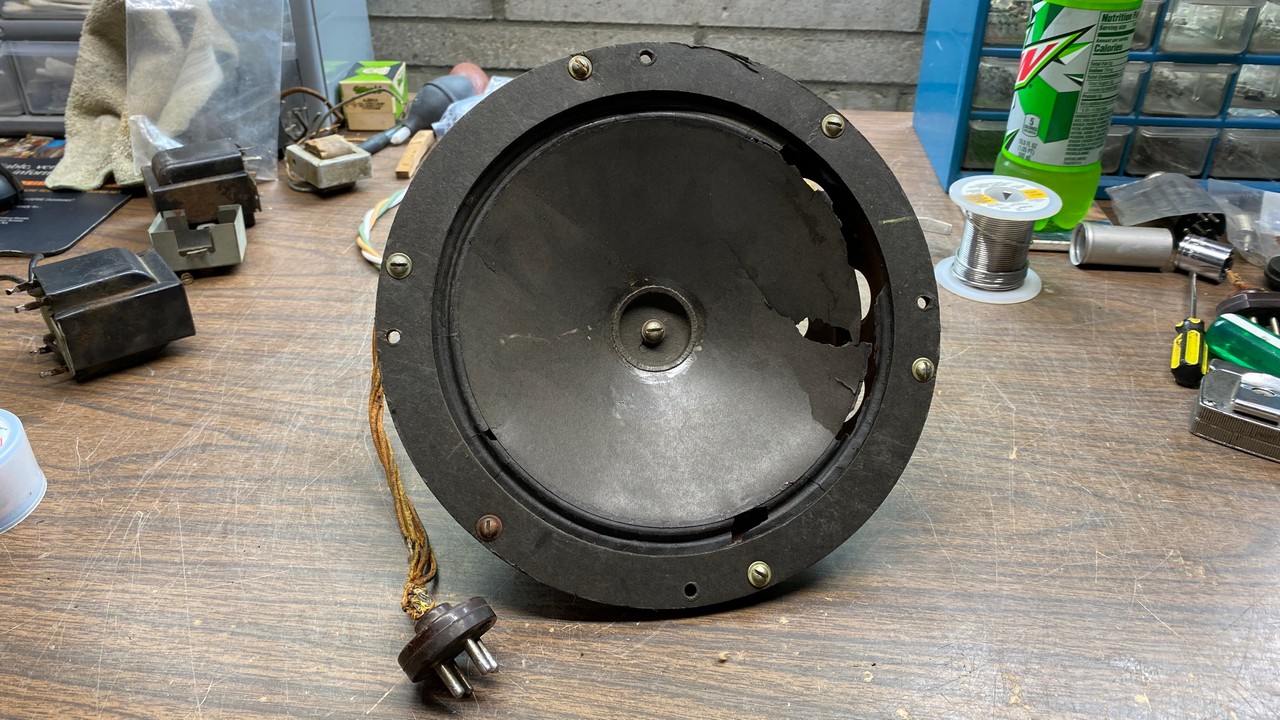
The Philco 20 speaker I chose as a candidate for conversion to a Philco 90 speaker.
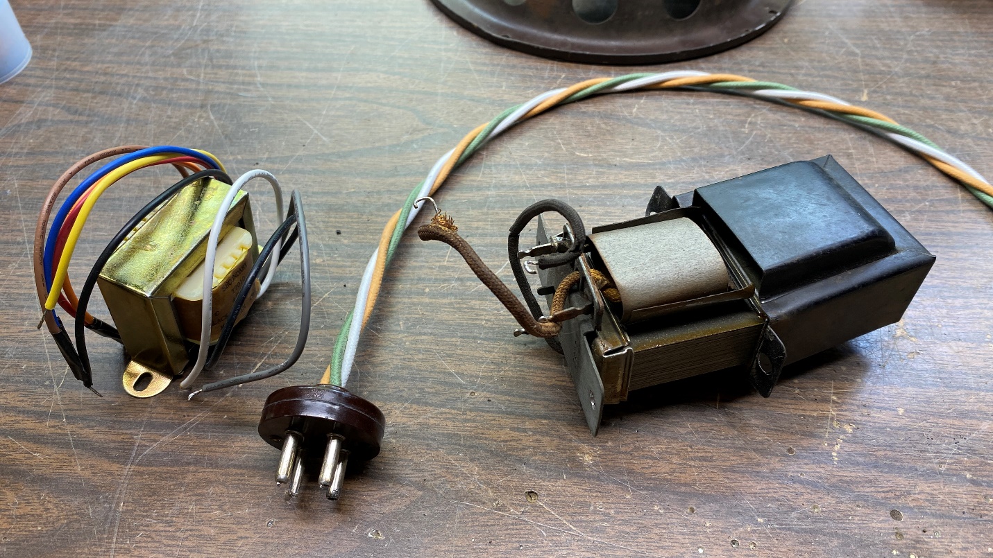
I began the work by cutting three 24 inch lengths of cloth covered, stranded 20 gauge wire for use as a new speaker cable. I happened to have a Philco speaker plug which was already separated (the two rivets had been removed), so I decided to use this plug to save a little time.
Studying the diagram of a model 70 and single-ended 90 speaker shown here at the Philcoradio.com site, I could clearly see which wire needed to go to what pin on the speaker plug. Not knowing the color coding of the speaker wires as Philco used them in 1930-31, I decided to follow Philco’s 1932-36 speaker wiring color standard of green for the plate lead, and white for the B+ lead (which also connects to one side of the field coil). Since I know of no source for modern cloth-covered 22 gauge wires with tracers (alternate color) in the cloth, instead of green-with-white-tracer, I used light brown. This wire would connect the other side of the field coil to the speaker plug.
I stripped each wire and soldered each one to their appropriate pins on the speaker plug.
Now, as I had no way to install new rivets on the speaker plug as was used originally, I took the easy way out and glued the halves together with J-B Weld.
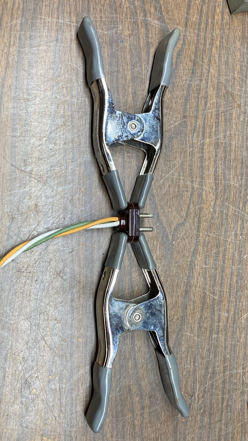
Two clamps are used on either side of the speaker plug to hold the halves in place while the glue dries.
The next day, the clamps were removed as the J-B Weld was dry by then. This part was then set aside for the time being.
So, I had a speaker frame with a good field coil. I had a speaker cable assembly with authentic Philco speaker plug. I had what I felt was a suitable replacement audio output transformer, but I wanted to be sure it would work as I wanted it to.
I had an old cone from a model 20 speaker which had a bad field coil. This cone was missing its center spider.
I had previously examined my test speaker, which had an identical line transformer, and decided I would try everything out using the same taps as the test speaker used.
I installed the cone with missing spider in my speaker frame. I felt the sound produced would be good enough for a brief test. I tack soldered the appropriate taps of the new line transformer to the appropriate wires of the speaker cable and did likewise with the leads of the speaker’s field coil. The transformer’s secondary leads were tack soldered to the voice coil terminals of the speaker.
I plugged this into the recently restored Philco 90 chassis, attached an antenna, and powered everything up. This seemed to be just as loud as the radio had been using the test speaker.
I then unhooked everything and unsoldered everything. My next job was to find a suitable old audio output transformer in which to hide the new transformer. I wanted to make the new transformer look more authentic as well as giving it an original method of hooking up the various wires.
I found a Philco part number 2673 single ended audio output transformer in my dwindling stash of parts. Unfortunately, its primary was open. I decided to hide my line transformer inside the old part 2673 shell, using its solder terminals as convenient places to terminate the two primary leads of the line transformer which I would be using.
The old transformer was constructed with a metal bottom plate, into which were installed two phenolic panels with the solder tabs built into the phenolic. The bottom plate was staked into the top cover through the two screw mounting holes. I had to grind off the stakes, which was not easy as I had to be careful not to destroy the bottom of the cover in the process. Soon, however, I had ground off the staking and the cover could be pulled free of the bottom plate, as well as from the old transformer itself.
The guts are removed from the old, bad part 2673 audio output transformer, so the new line transformer may be hidden inside.
I unsoldered the old primary leads from the solder terminals on the bottom plate, and threw the old transformer into the trash. I then prepared the new transformer to be placed inside the old cover. I cut off the unused primary leads and one of the three secondary leads, and used hot glue to insulate these cut leads and keep them from shorting to the metal cover or to each other.
I removed the metal frame from the new transformer, and then placed the transformer body into the old cover. The primary leads were stripped and the bare ends were threaded through the holes in the proper solder lugs in the bottom plate. The secondary leads were threaded through the holes in the bottom plate which had been made for that purpose. I then bolted the assembly to the speaker frame to hold it all together.
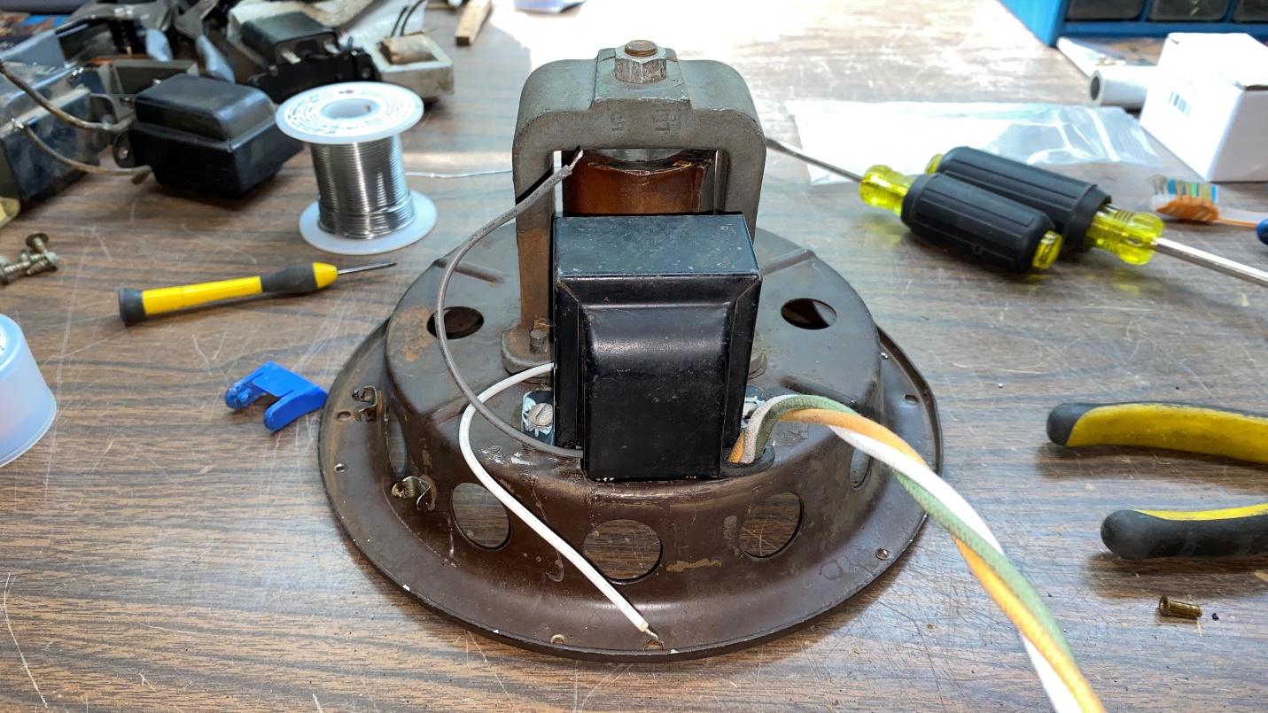
Using a new rubber grommet, the speaker cable was then installed in the speaker frame. I then proceeded to connect all the leads inside the frame as shown below.
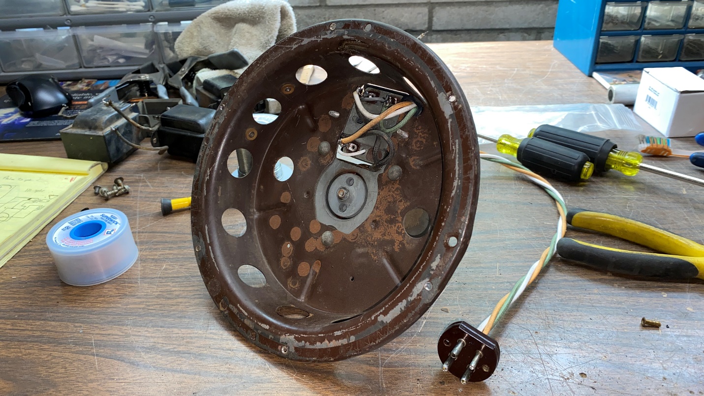
The speaker frame now has a new audio transformer and speaker cable.
I had to be very careful with the field coil leads as they were very dry and brittle.
This is how the speaker looked after installation of a new transformer and speaker cable, and just before installation of a suitable cone.
Now I needed a cone for my speaker. I had a new replacement cone, but as luck would have it, it was just a little too deep to fit inside the basket of the speaker!
I looked around in my parts stash, and decided to use an original old cone from a Philco R-3 permanent magnet speaker. The cone was not perfect, but would be better than nothing. There was one problem, though – its voice coil was smaller than what was needed in the speaker I was putting together. These early “pie pan” Philco speakers (K, K-2, and K-3) have 1-1/4 inch voice coils. The Philco K series speakers of 1932-38 have 1 inch voice coils, as did this R-3 speaker.
I could give up at this point and send the speaker somewhere to be reconed, or I could get desperate and attempt removing a voice coil from one cone and applying it to the cone I proposed to use in this speaker project. I chose the latter.
I applied acetone around the edge of the voice coil of the cone which had no spider. Soon, the voice coil had come free from the old cone.
I happened to have some speaker cement, and used this to carefully glue the voice coil to the cone I wanted to use in the speaker. (Its smaller voice coil had come off when I removed the cone from its speaker, but fortunately this did no further damage to the cone.) I guessed at exactly where to place the voice coil to get it as centered in the cone as I could.
Then, using three shims cut from an old business card, while the glue was still soft I pushed the cone/voice coil assembly into the gap of the speaker, with the shims evenly spaced around the voice coil gap and placed in such a manner that I could pull them free the next day once the glue was fully dried.
The shims would keep the voice coil centered in the voice coil gap.
With the shims in place, I went ahead and attached all the mounting screws. Then, the speaker was set aside to dry overnight.
The next morning, I put the speaker on my workbench. Using my long needle nose pliers, I carefully removed each shim from the voice coil gap.
This is how the reconed speaker now looked:
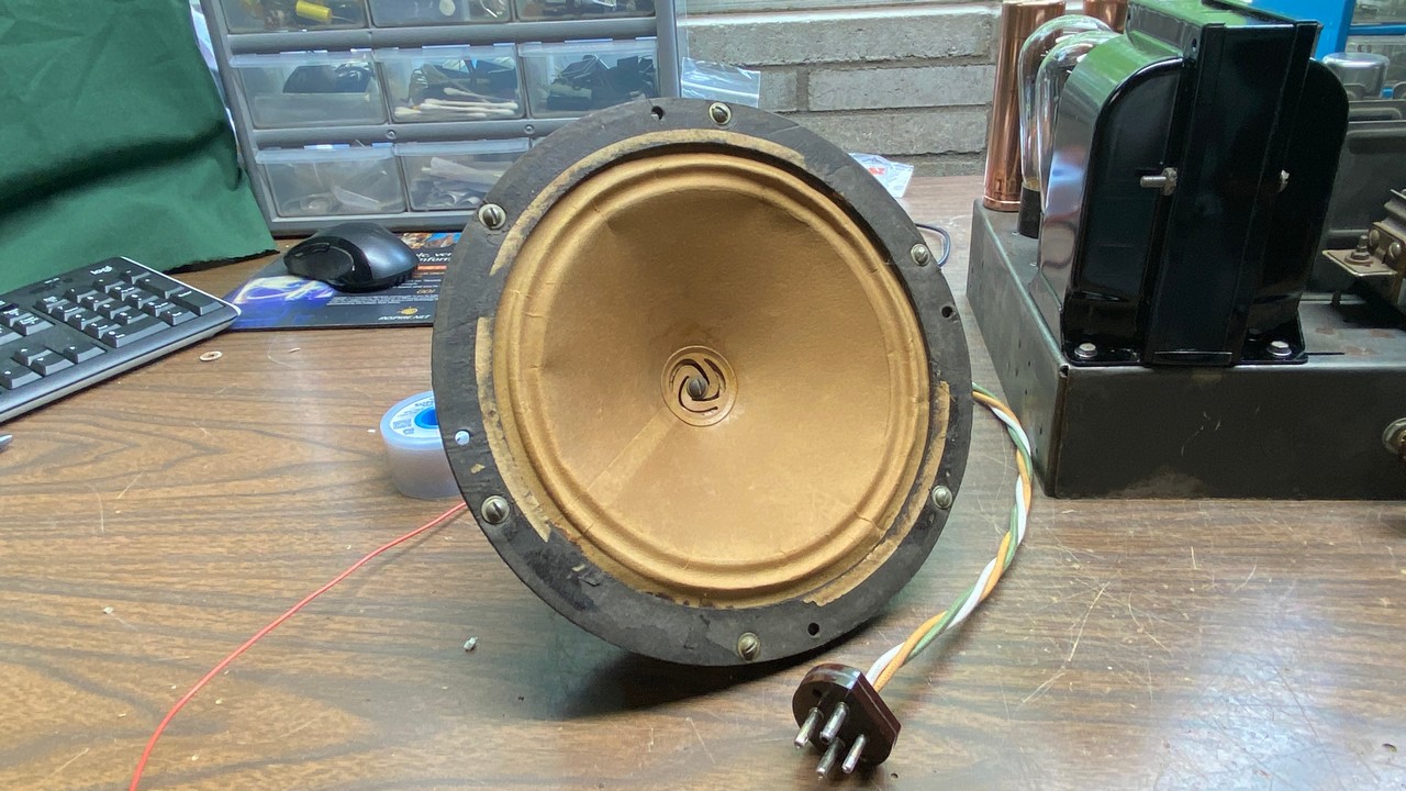
A freshly reconed Philco 90 speaker.
I promptly plugged the speaker into my restored Philco model 90 chassis, attached an antenna, and turned it on.
In about 45 seconds, I was hearing music from my home AM transmitter. It sounded fine, as loud as the test speaker had been and with the same audio quality.
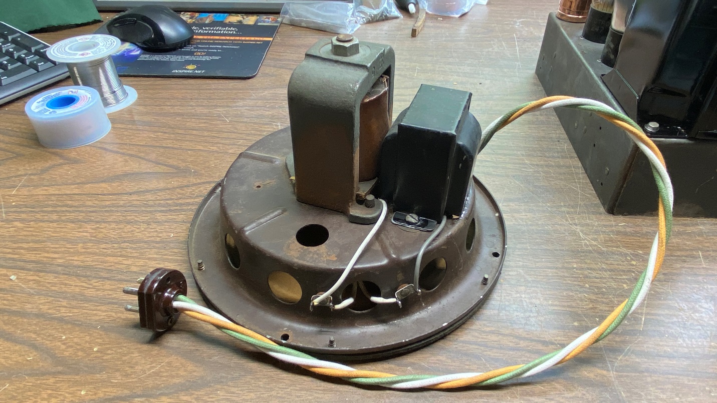
Another view of the rebuilt speaker.
What a relief! It is always a good feeling when a job like this turns out well.
Now, it was time to put everything together in that reproduction model 90 cathedral cabinet which was made by Steve Davis, and had been sitting around here for several years.
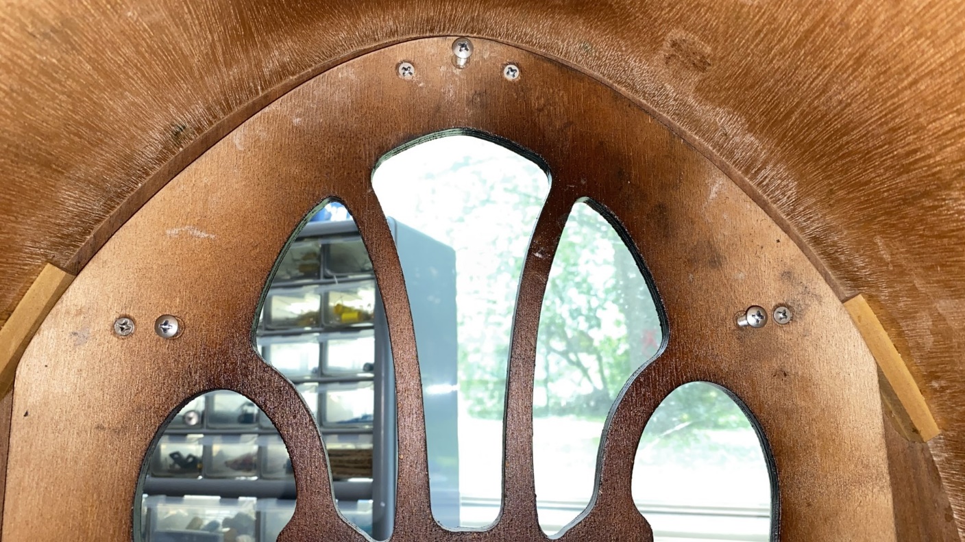
I had been saving a brass Philco 90 escutcheon just for this cabinet. I polished it up with some Brasso so it would look as good as the cabinet did. With help from Debbie, I soon had the escutcheon mounted over the dial opening in the cabinet’s front panel.
I thought I was going to have to glue some grille cloth onto a backing board, but it turned out that I already had a backing board with new 70/90 cloth on it, ready to go. My next thought was that I would need three mounting screws to attach the speaker to the cabinet on the inside. But this was also no problem – the new cabinet came with speaker mounting screws, already in place!
The Steve Davis reproduction cabinet came with new speaker mounting screws.
Before long, I had the grille cloth, speaker, and chassis installed in the cabinet. The first thing I did after I put everything together was to try the radio out once again. And, it still played just as well as it had done previously.
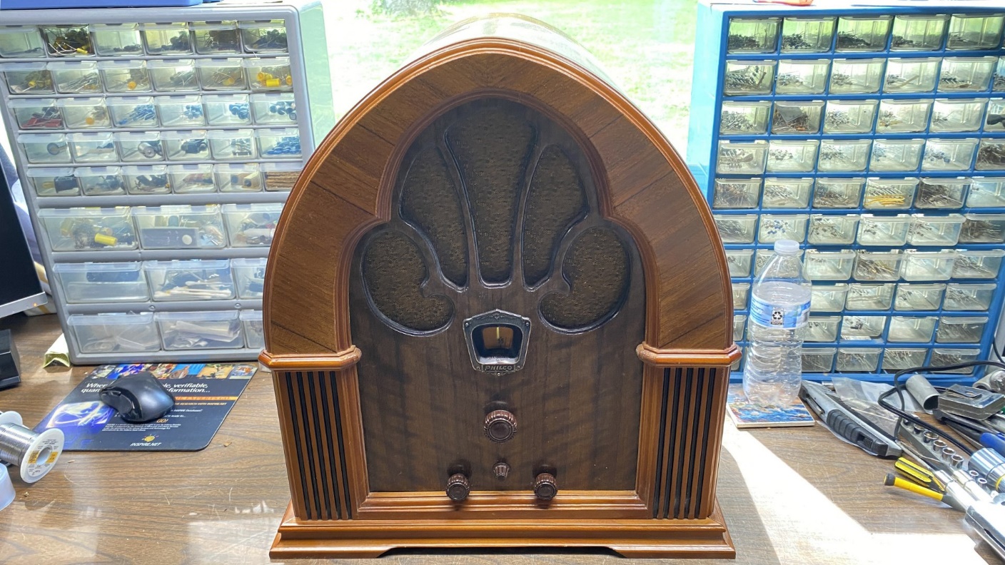
The completed Philco 90 cathedral.
I apologize – this is not the best photo of a radio I have ever taken. I was hampered by the afternoon sun coming through the picture window behind the radio. Yes, I could have closed the curtains. Oh well.
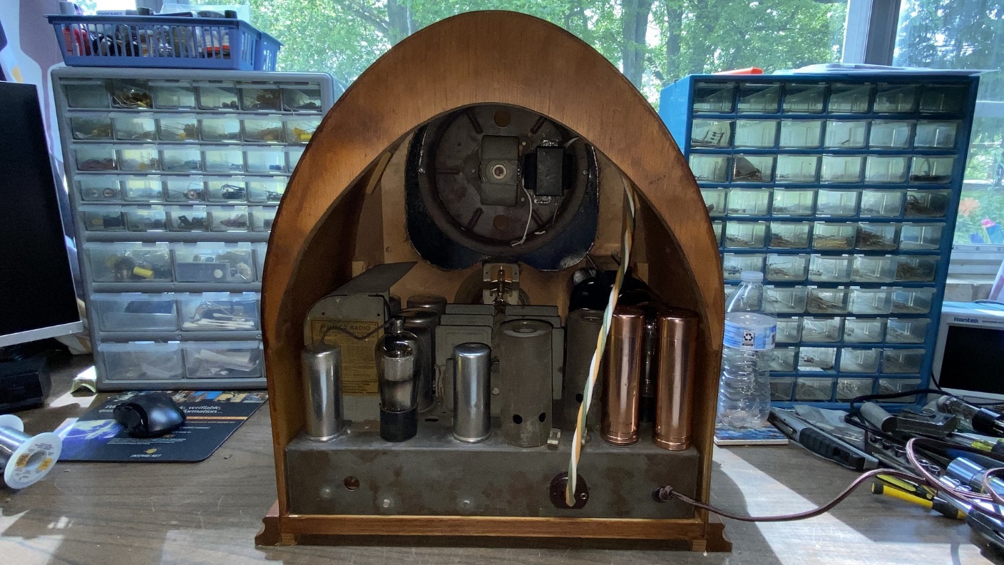
Rear view of the completed Philco 90 cathedral.
And with that, this concludes not only the tale of rebuilding the speaker, but also the entire saga of the Philco 90 restoration. This radio is already one of my favorites, and I like it even more now that it is finally complete and working.