I recently discovered that the 1929 Philco model 83 is not identical to Model 87 except for the fact that model 83 operates on 25 cycle AC while model 87 operates on 60 cycle AC current. As it turns out, the 1929 Philco model 62 radio is also not quite the same as model 65.
Model 62 was sold in the same table model, lowboy, highboy, and highboy de luxe cabinets as was model 65. However, there are differences between the two chassis which go beyond the choice of 25 cycle or 60 cycle AC current.
I wish to point out those differences, and to present you with useful service information in the event you may need to work on a model 62.
Model 62 does not use push-pull type 45 output tubes. Instead, it uses push-pull 71A output tubes. Model 62’s power transformer is different from the Model 65 power transformer; it has an extra 5 volt filament winding for the 71A tubes instead of a 2.5 volt winding for 45 tubes. The dial lamp, which is powered by the output tube filament circuit, is 5 volts instead of 2.5 volts. This will actually make it easier to replace the dial lamp – you can use a screw base LED lamp designed for 6.3 volt operation and it will work fine.
Let’s compare the two. First, a schematic of Model 65:
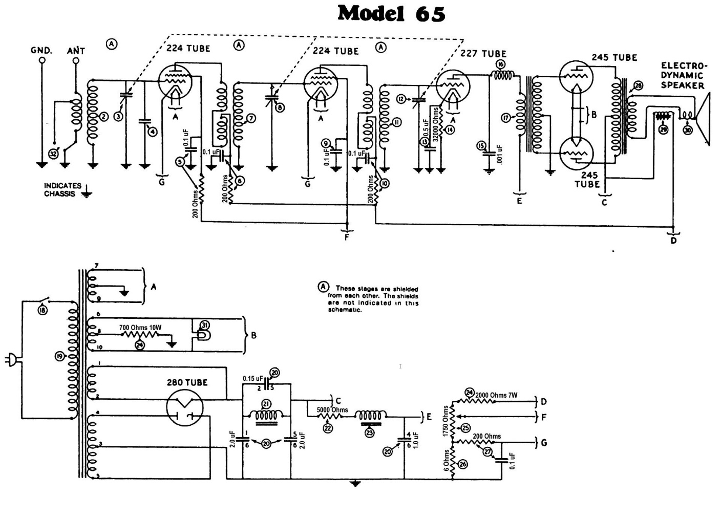
Philco Model 65 schematic.
And now here is a Model 62 schematic:
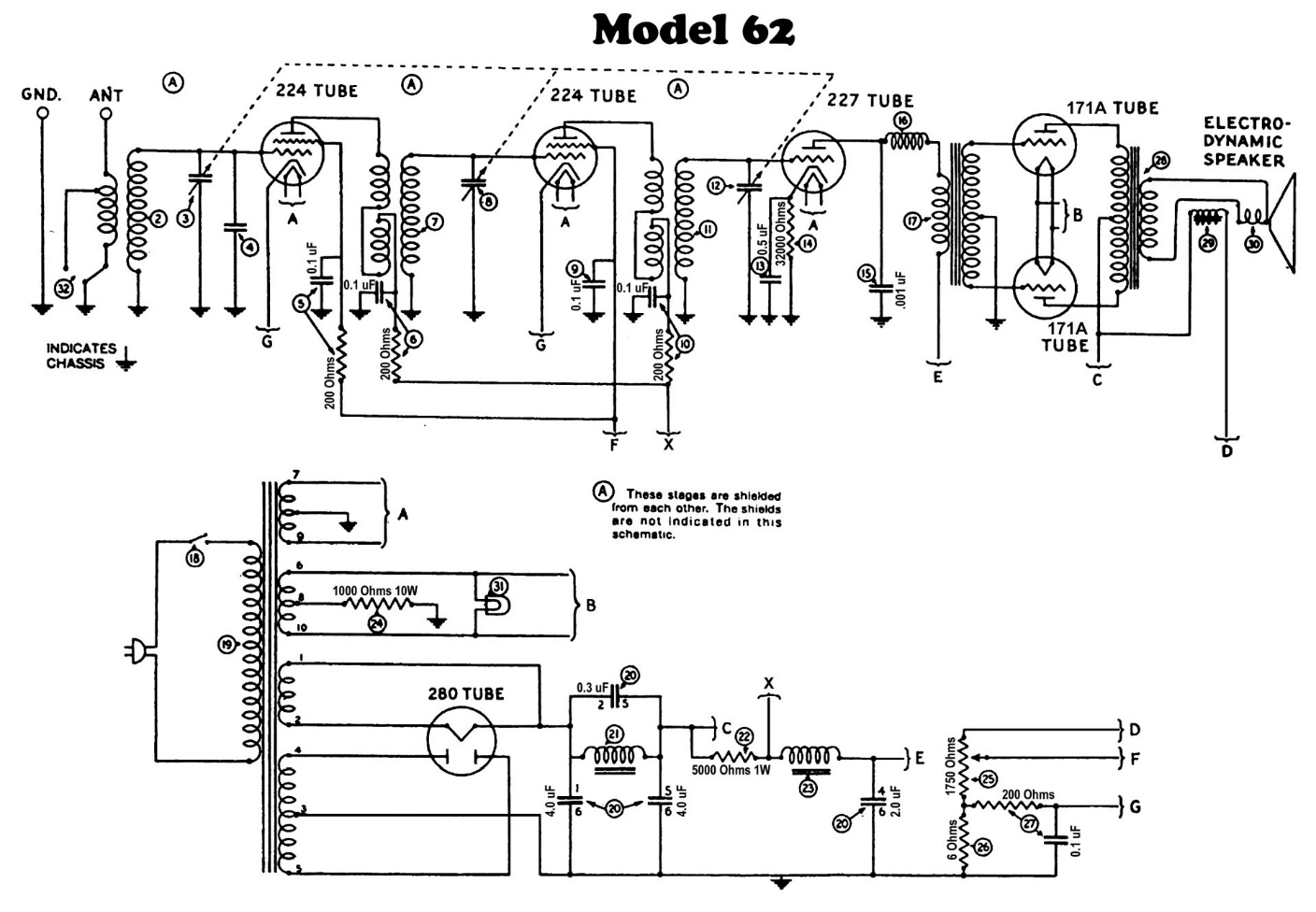
Philco Model 62 schematic.
Other than the two 71A output tubes in place of the 45 output tubes used in Model 65, the differences in the two radios are chiefly in the power supply. The 2000 ohm section of resistor (24) is eliminated in model 62. The 700 ohm section of this same resistor is replaced by a 1000 ohm resistor, so the 71A tubes will receive proper bias. The plates of the 24 tubes receive their B+ voltages from a different point, shown as point X on the model 62 schematic.
Notice the values of the capacitors used in the filter condenser block, part (20). These values are not documented, so I guessed at them in the schematic above. Keep in mind that both the United States and Canada have used 60 cycle (60 Hz) AC current for decades now. Therefore, if you have a model 62 to restore, you can use the model 65 values and the radio will work fine.
You can see the values used in the Model 65 block below.
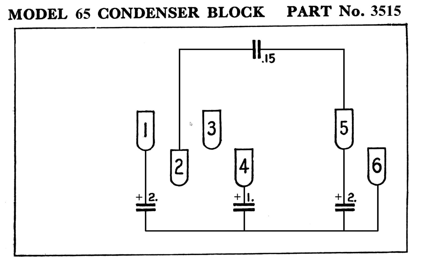
Philco Model 65 filter condenser block. This diagram may be used to replace the filter capacitors in Model 62.
It is my hope that the above information will prove helpful, especially since Philco apparently did not properly document their Model 62 radio.