In our last exciting installment of the Philco 29/45 saga, I had replaced the wires of each of the three IF transformers, installed new tuning condenser grommets and reinstalled the tuning condenser, and made a test fitting of the Philco 610 (type P-27) speaker. Now, it was time to try to finish everything up.
I shortened the speaker wires as needed and made a final installation of the speaker. This was followed by installation of the AC line bypass Bakelite block and the volume control. The final wiring was made to the various terminals of the two terminal boards.
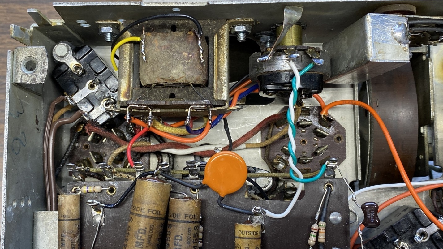
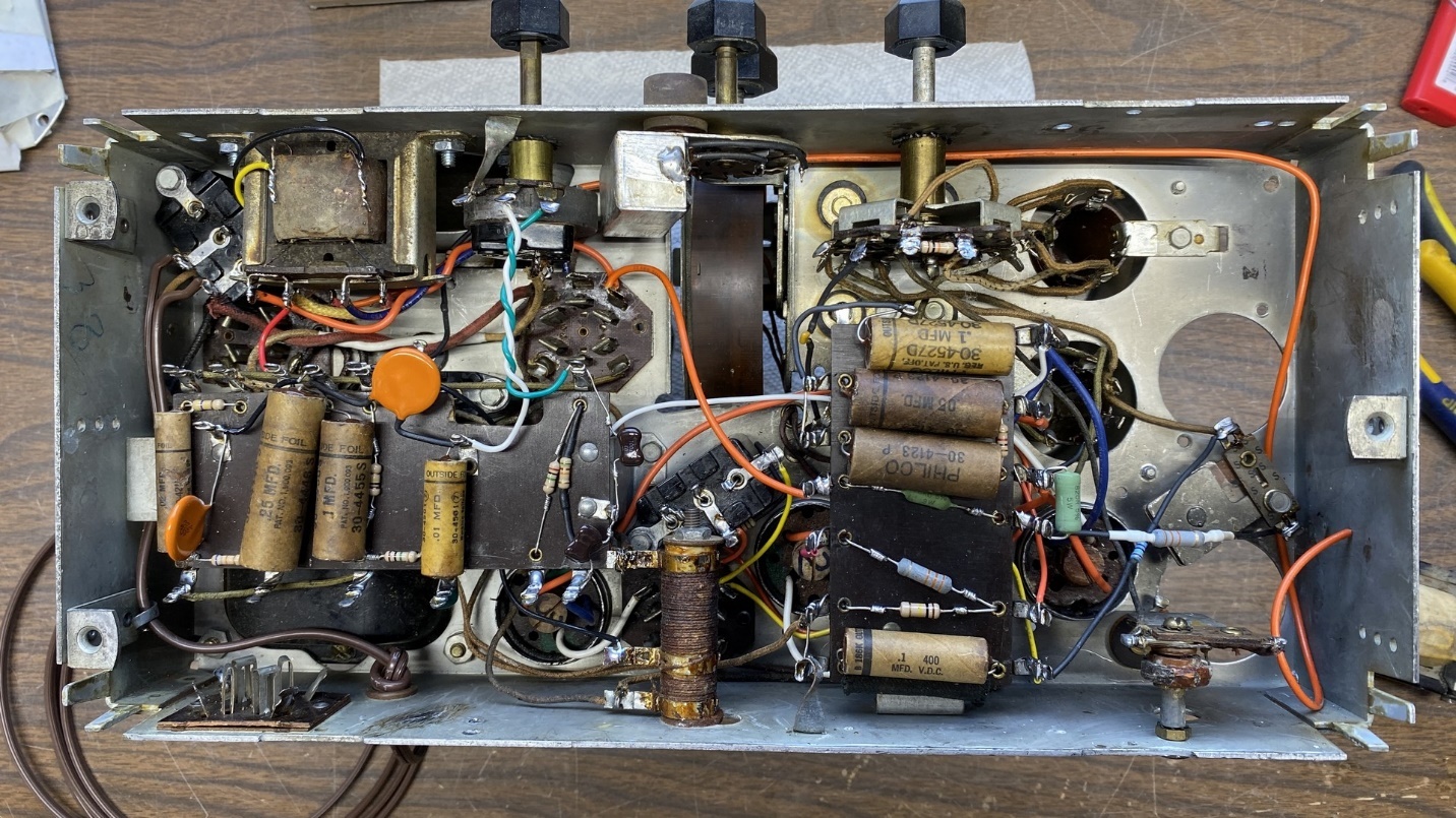
Speaker, audio output transformer, and volume control reinstalled and reconnected.
I needed to do something about the electrolytic capacitors before I could finish the set up and try it out. Having previously decided to restuff the electrolytic cans, I began this process by cutting both of them open.
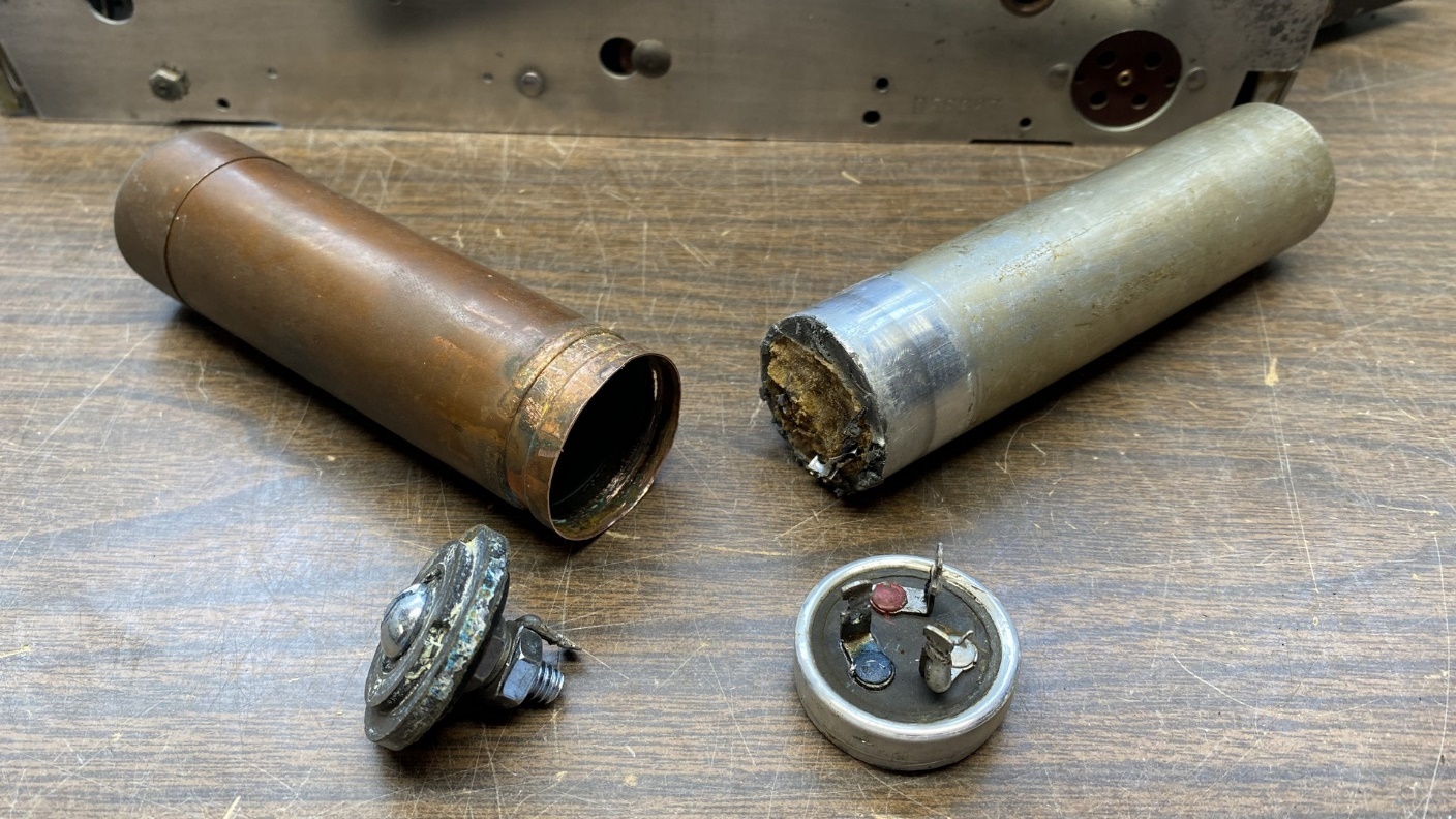
The ends have been cut off both of these electrolytic condenser cans.
I started with the simpler of the two, the single section copper Mershon electrolytic. Once the lower lip was cut off, I pulled out the Bakelite end piece and proceeded to replace its original aluminum bolt and nut with a tin plated steel 10-24 bolt and nuts. I knew I would be able to solder to the head of this bolt, which is why it was selected.
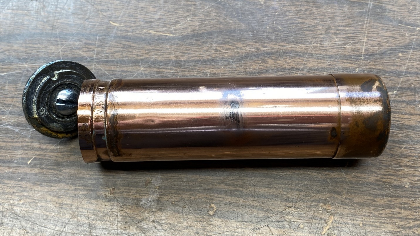
The copper Mershon electrolytic after polishing, ready to be restuffed with a new capacitor.
I had purchased a few 10 uF, 600 volt film capacitors to replace the electrolytics in this radio. I extended the lead of one of these capacitors and soldered that lead to the inner copper shell of the Mershon. This would become the negative terminal of the capacitor. The other lead of the film capacitor was soldered to the head of the new bolt which was attached to the Bakelite insulator.
New capacitor attached to the inside of the copper can and to the bolt, which will serve as the positive terminal.
Once this was done, I carefully pushed the new film capacitor into the Mershon can, pushed the Bakelite insulator back into place at the end of the can, and used some J-B Weld to hold it in place.
Now it was time to turn my attention to the other electrolytic, which contained three capacitors in one can.
I attempted to use my two remaining film capacitors along with a smaller, 50 volt film unit, to replace the three electrolytics. However, it soon became apparent that this configuration was not going to fit into the can.
The film capacitors proved to be too much for one can.
I saw that I was going to have no choice but to use new electrolytic capacitors so that they would physically fit inside the aluminum can.
Soon, I had two 10 uF, 450 volt electrolytics and one 10 uF, 50 volt electrolytic wired together and ready to install.
New electrolytics ready to be stuffed into an aluminum electrolytic can.
For the outer shell of the can, I decided to take the easy way out and cut off the bottom end of an old wet electrolytic. Once this was cleaned out, it proved to be much easier to deal with than trying to melt out the insides of the original aluminum electrolytic shell.
The restuffed three-section electrolytic is ready to be reinstalled in the radio.
I polished the aluminum shell of this restuffed electrolytic, and then reinstalled both cans into the radio.
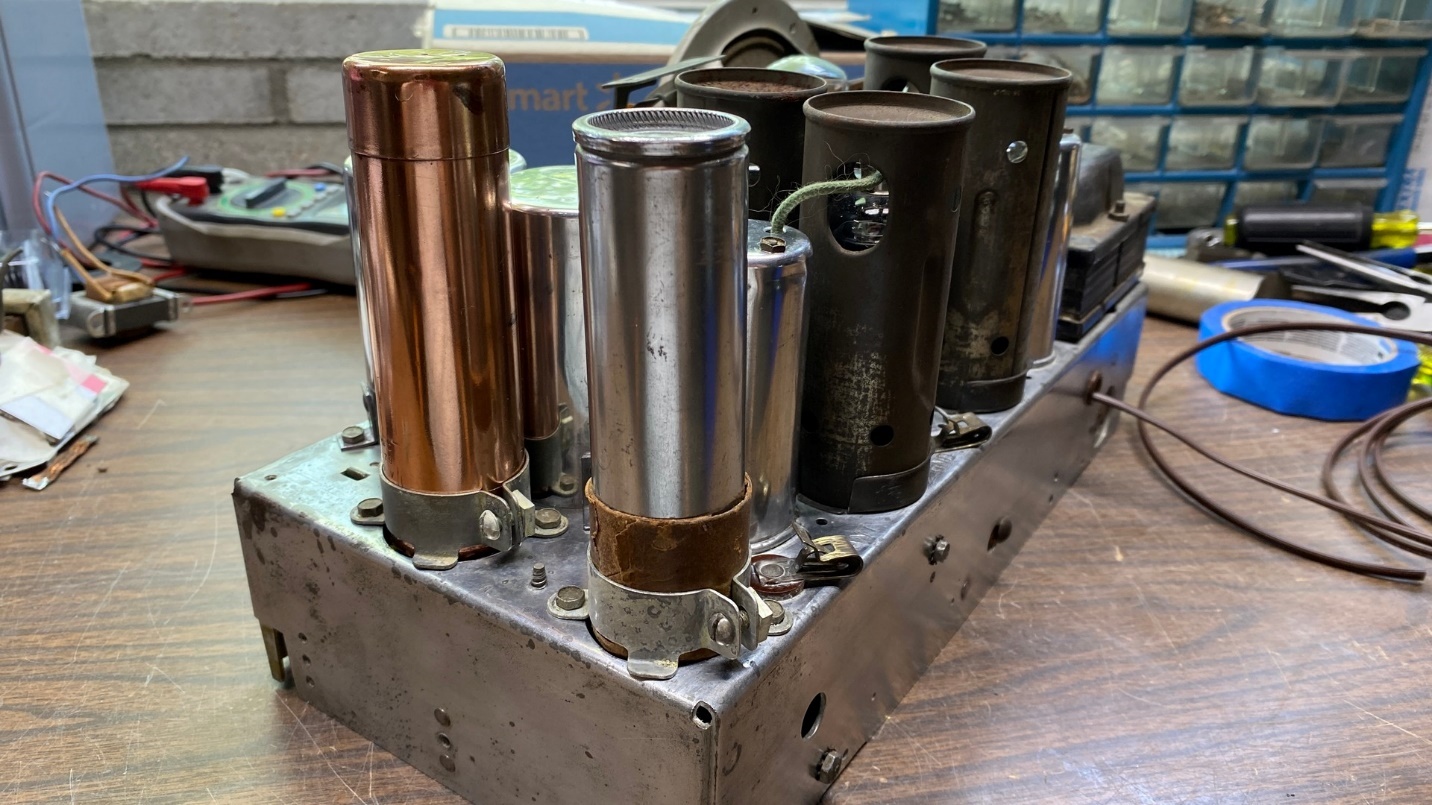
Restuffed electrolytic capacitors back in place on the radio.
Now came the moment of truth. Was this radio going to work after months of slow but deliberate rebuilding?
I plugged the radio in and turned it on. Having previously tested the tubes, I knew they were all good.
Soon, I could hear a little static. But I was quite dismayed to see a tiny plume of smoke emanating from under the chassis!
I quickly turned the radio off, unplugged it, and turned the chassis upside down.
Not immediately noticing where the smoke was coming from, I plugged it back in and turned it on briefly – just long enough to see the smoke coming from resistor (37), a 5K, 2 watt resistor which feeds B+ voltage to the plates of the IF tubes and to the plate of the 6A7 converter tube.
With the radio turned off and unplugged again, a quick resistance check found a near short to ground at the end of resistor (37) which connects to resistor (66). I disconnected some wires and did some further checking. I found that when the B+ lead from the 2nd IF transformer was disconnected, the resistance readings seemed to be normal. So, once again, I plugged the radio in and turned it on with the B+ wire from the 2nd IF transformer disconnected. The B+ voltage reading also appeared to be normal.
I had a real puzzler on my hands. Resistance readings showed the B+ lead of the 2nd IF transformer was not obviously shorted to anything, yet it certainly appeared to be shorted when connected into the circuit.
A friend of mine offered to send me a Philco 45 chassis for parts, and I readily accepted his kind and generous offer. It looks like I could use a 2nd IF transformer.
So, while I wait for that to arrive, I am going to bring this installment of the Philco 29/45 story to an end. Next time, after the parts chassis arrives, I will replace that 2nd IF transformer and try the radio out again.