Finally, I try the radio out.
I installed the seven globe-shaped tubes, which I had previously selected, into the Philco 87 chassis, along with the taper-top type 80 which came with the radio.
I pulled its speaker out of storage and plugged it into the speaker socket on top of the chassis.
I connected my longwire antenna to the radio’s ANT terminal.
I plugged the radio into my Variac as a precaution. Slowly bringing the voltage up, I began to hear noise once I reached 110 volts on the Variac.
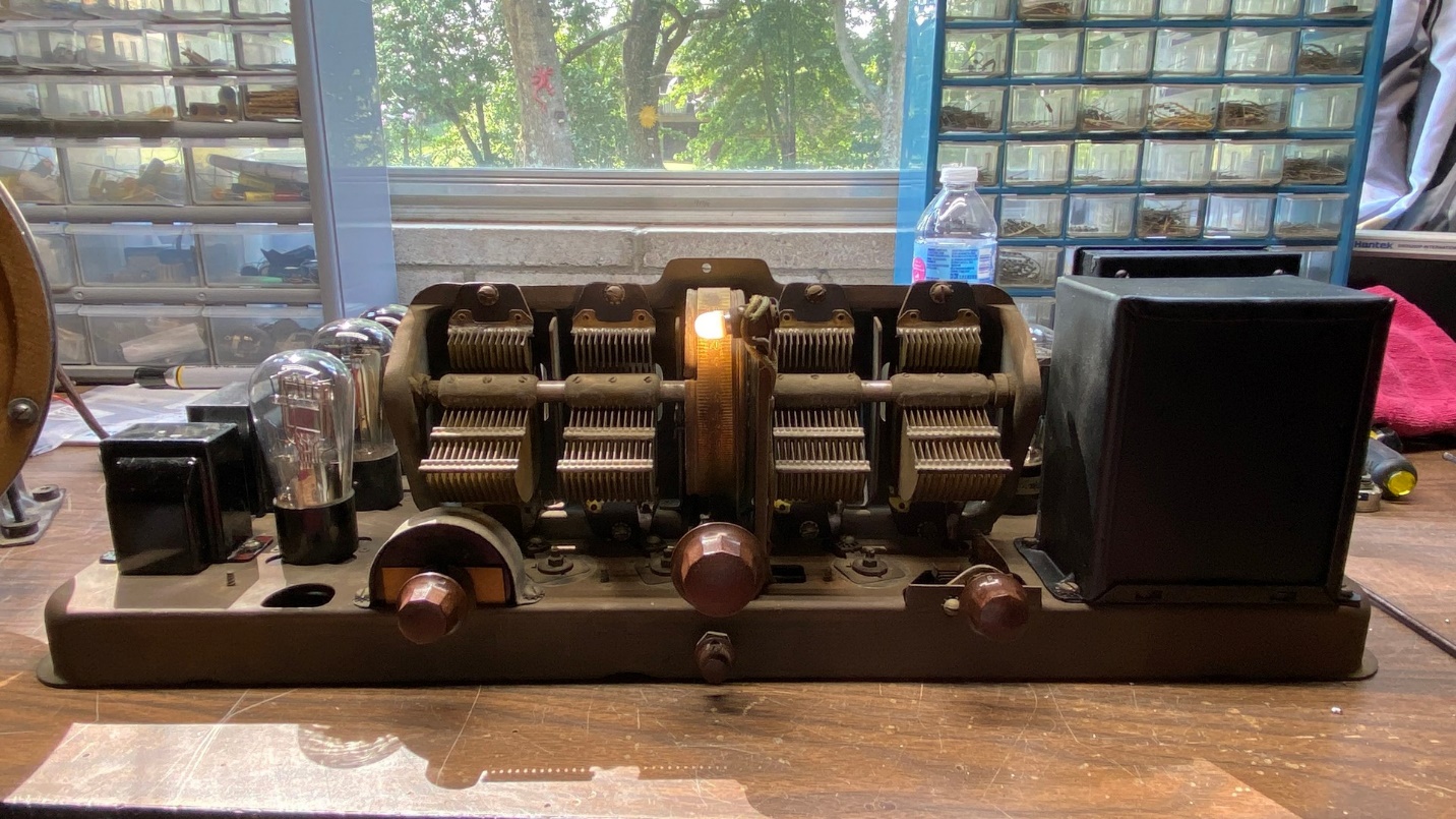
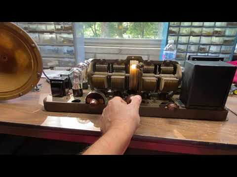
The Philco 87 on its first trial run. Notice the 6 volt LED lamp is brightly illuminated even though it is operating at 5 volts.
The radio was working. Sort of. There was a great deal of squealing which I was able to mostly alleviate by adjusting the volume and fine tuning controls.
But then the volume went away. I tapped on a few tubes and the volume came back.
I then turned the radio off, unplugged it and the Variac, removed the tubes and flipped the chassis upside down. After this, I proceeded to carefully bend each tube socket contact so that they would make better contact with the tube pins.
While I was at it, I decided to pull the volume control from my Philco 83 parts chassis since it was an original part. The volume control in my 87 chassis was a later replacement.
I noticed the 83 volume control had a shield around it on top of the chassis.
I unsoldered and removed the replacement control from the 87 and did likewise with the 83 control. Then, the 83 volume control was installed into the 87 chassis, followed by the metal shield.
After doing all this, I reinstalled the tubes and tried the radio again.
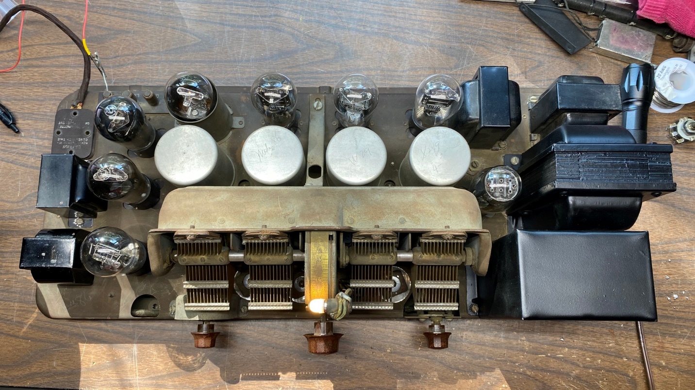
All but one of the tubes in the 87 chassis are globe-shaped.
The radio came back to life. But I noticed that one of the 71A filaments was not lit. I wiggled the tube and…no joy. So, I turned the radio off again, removed the tubes and the speaker plug, flipped the chassis over, and then removed the 92 year old solder from the contacts of both 71A tube sockets with my soldering gun and desoldering braid. After this, I made sure the wires were tight against each contact for a good mechanical joint at each one. I then flowed new solder onto each contact.
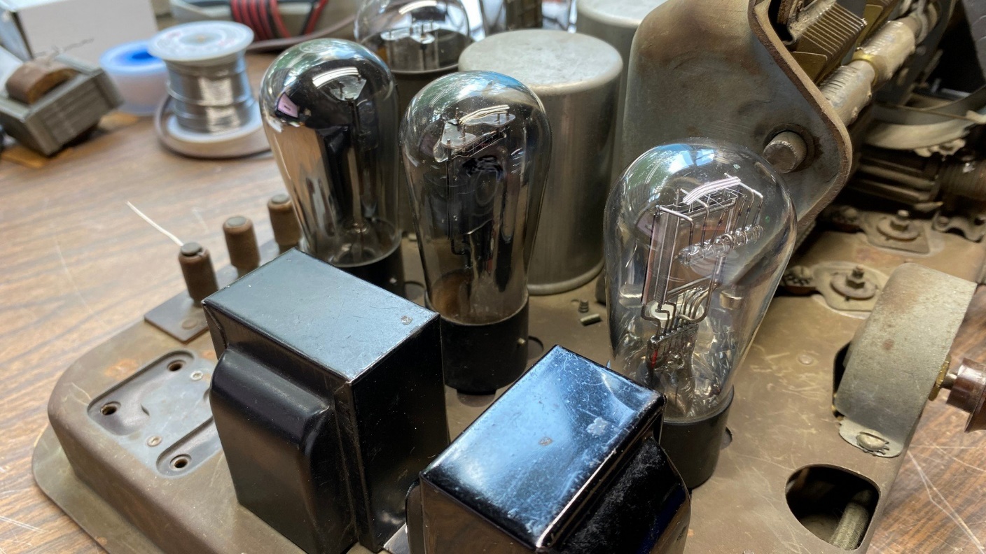
Two globe-shaped 71A tubes, at center and at right.
Turning the chassis right side up again, I reinstalled the tubes, plugged in the speaker, plugged the radio in and turned it back on.
Now, it was louder since both 71A filaments were lit up. The radio sounded better, also.
So, I turned it off again, removed tubes and speaker plug, turned the chassis upside down and reinstalled the bottom chassis cover.
Flipping it back over again, I ran one more test which I recorded. Please watch the video below.
The radio is now ready for an alignment and neutralization. You can read about the neutralization procedure here. I feel that once the radio is aligned and neutralized, that this should help with the squealing (oscillation).
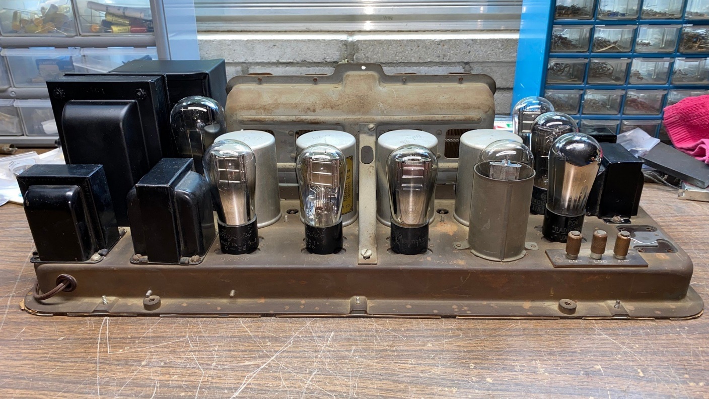
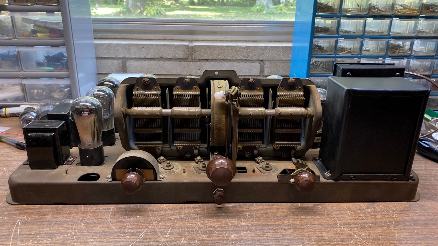
Back view of model 87 chassis, now sporting a complete set of globe-shaped tubes.
Once I have aligned and neutralized the radio chassis, it (along with its matching speaker) will be reinstalled in its highboy cabinet.
I have now replaced the taper-top 80 with a period correct, globe-shaped 80 tube.
The transformer transplant and slight modifications were a success. This radio will live on now as a Model 83. I just might revisit those modified audio transformers in the future, however, by replacing them with new P-T156 interstage transformers from Antique Electronic Supply. Doing so would give the audio volume a bit of a boost.
And that brings this restoration series to a close. I hope you have enjoyed reading it. Now, I will think about what I want to restore – and write about – next.