In our last exciting installment of this excellent 38-690 adventure, I had determined that I needed to check the AM antenna coil, try to determine what was causing the tuning to be so stiff, and find out just what was causing some binding between the tuning and the bandswitch assembly.
I pulled out the 38-690’s upper chassis and completely disassembled everything from the tuning assembly.
I was certain that the vernier drive of the tuning assembly needed to be removed, cleaned, and reassembled. I have run into that in smaller Philco radios as well as RCA radios with dual tuning knobs, and the vernier drives in these were easy to remove, disassemble, clean, regrease and reassemble. Once that was done, tuning that had been rough and difficult, often with a nonfunctioning slow speed tuning (inner knob), was restored to proper operation each time.
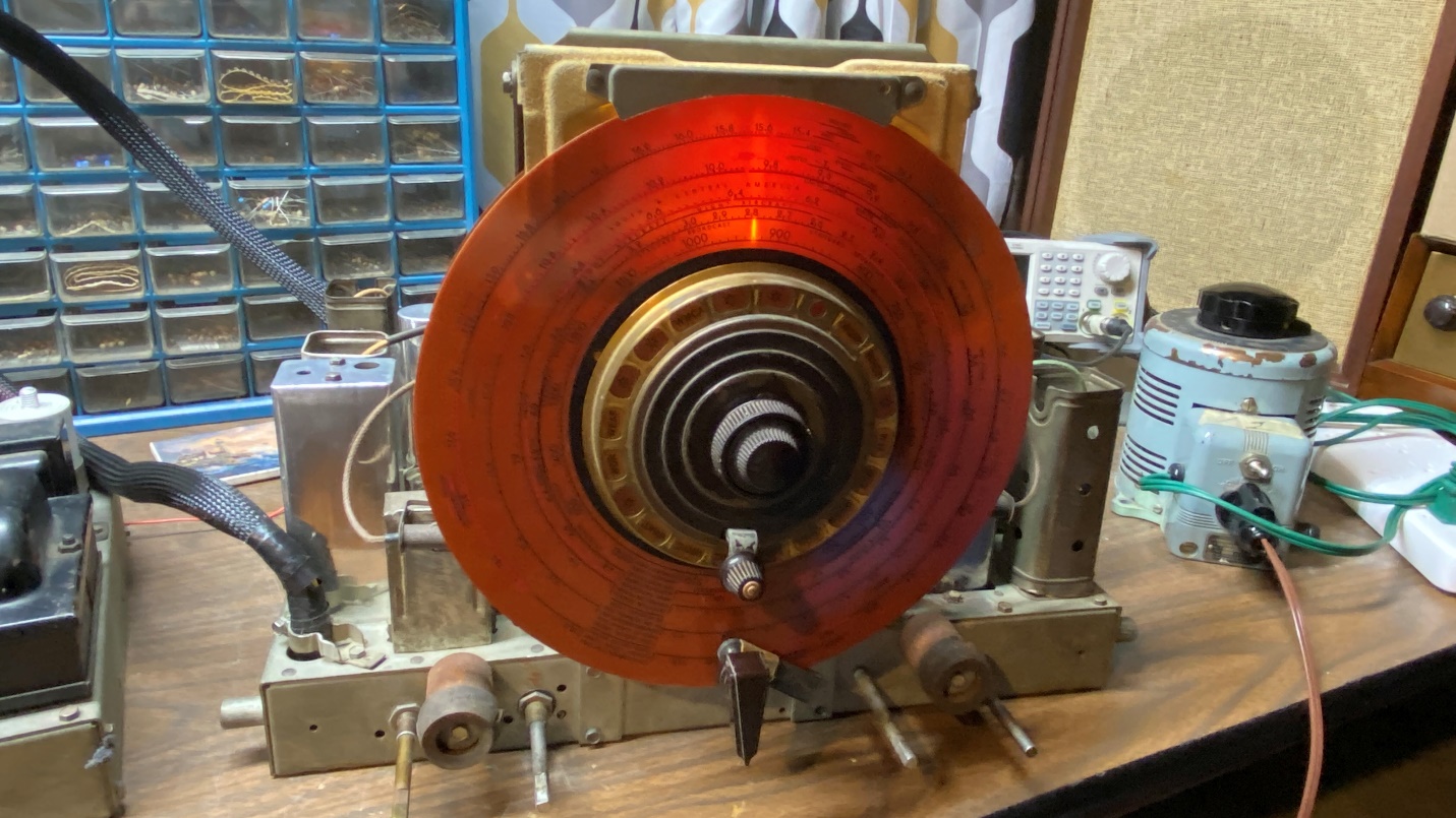
The 38-690 upper chassis in operation.
I had read in Philco Service Bulletin 273, which covers Philco’s Automatic Tuning mechanism, that the vernier drive could be removed as follows:
(Once the dial scale and other parts had been removed from the assembly) Now loosen and remove lock pin (22). To do this, hold a piece of wood (small block) firmly on the side of the vernier drive housing on which the lock pin is located. Tap the end of the wooden block sharply with a hammer until pin is loosened.
There is only one problem with that: 80+ years on, you can beat the end of the wooden block with a hammer for hours…and the lock pin will only pop out ever so slightly…not enough to grab it with a pair of pliers (or anything else for that matter).
So, I was defeated on the vernier drive.
I could hear David Grimes laughing again.
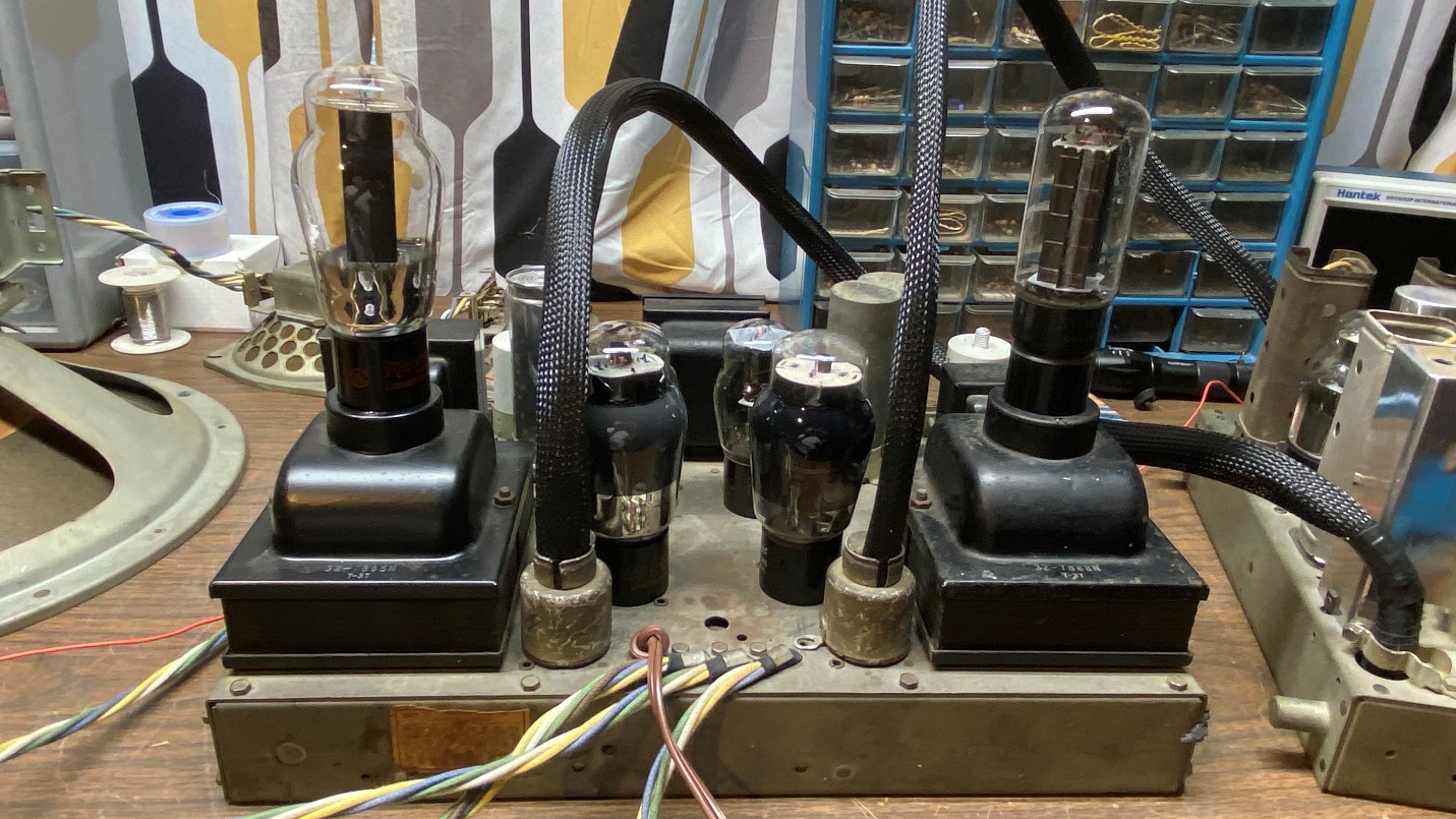
The 38-690 amp/power supply chassis in operation.
I then reassembled all the parts back onto the tuning assembly, lightly lubricating all friction/pivoting points as I went. Now, trying it out again, the tuning was slightly better, and the band switch was no longer switching itself as I tuned up the dial.
Next, I flipped the chassis upside down and tested primary and secondary of the AM antenna coil. Both were just fine. Now I know for certain that the reason it only picked up a couple AM stations on my last test was because I had my outdoor longwire antenna switched to the “off” or “grounded” position, which grounds the antenna for safety in case of thunderstorms (it also has a lightning arrestor). When grounded, of course little if any signal will be picked up.
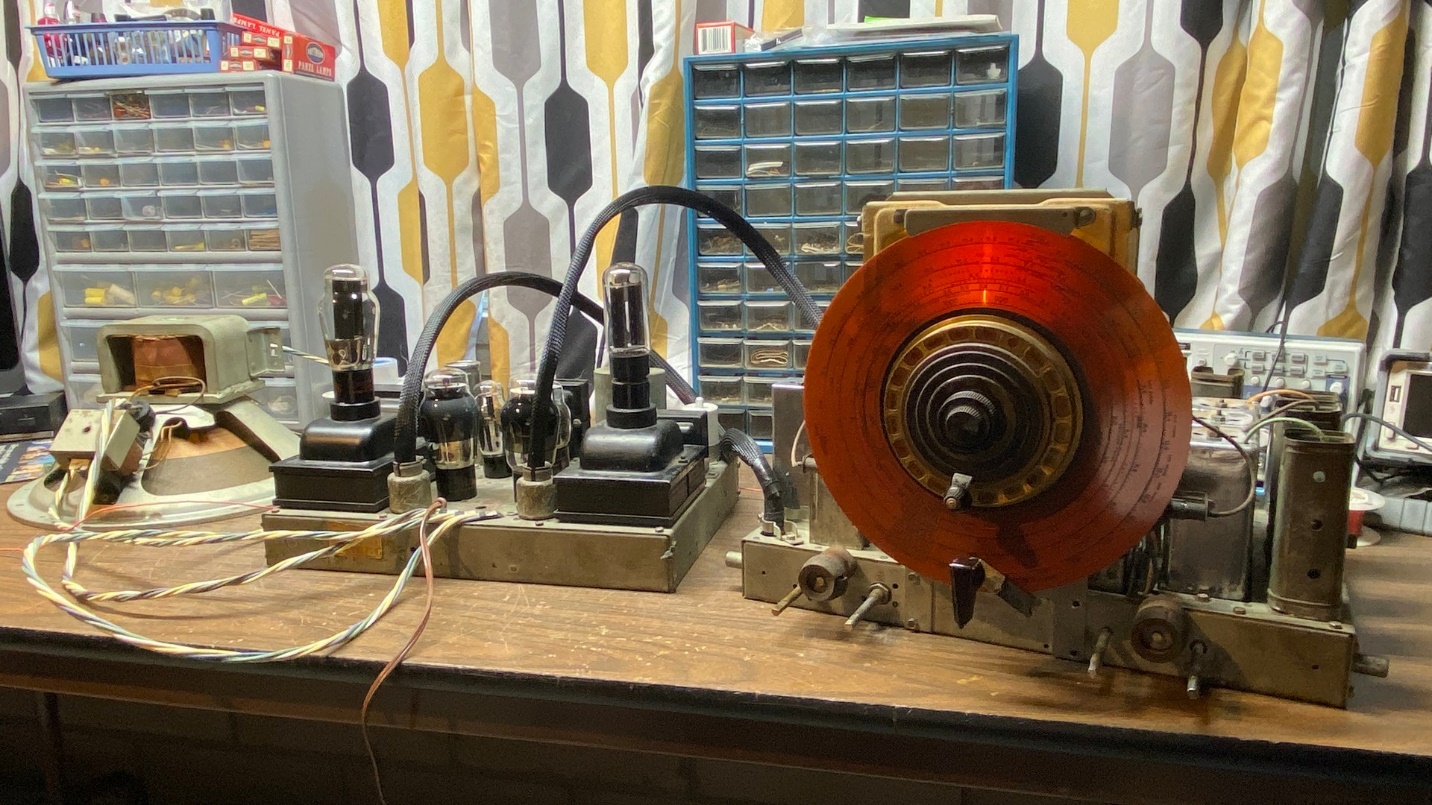
I only needed to perform one final test, to make sure all was well on AM. So…out came all of the components (upper chassis, lower chassis, woofer, two tweeters) and everything was put together on the workbench. This time, I made sure the outdoor longwire antenna was turned on (ungrounded) after I clipped the small alligator clip to the upper chassis’ RED antenna terminal.
Did it work?
You be the judge…
There was NO sizzling, NO popping, as the radio warmed up nor after warmup was complete and the radio was in operation. I was frankly amazed at how sensitive the radio was. There are no AM stations in this area on the low end of the AM band; but from around 700 kc and up, it picked up lots of stations as you heard in the video above.
While I was at it, I tried the SW bands. They seem to be ok, as I was able to hear noise and a few stations on each.
Observed issues:
Alignment was off due to mechanical misalignment of the dial scale in respect to the tuning assembly.
The volume control seems a bit flaky. I may try to give it a shot of FaderLube.
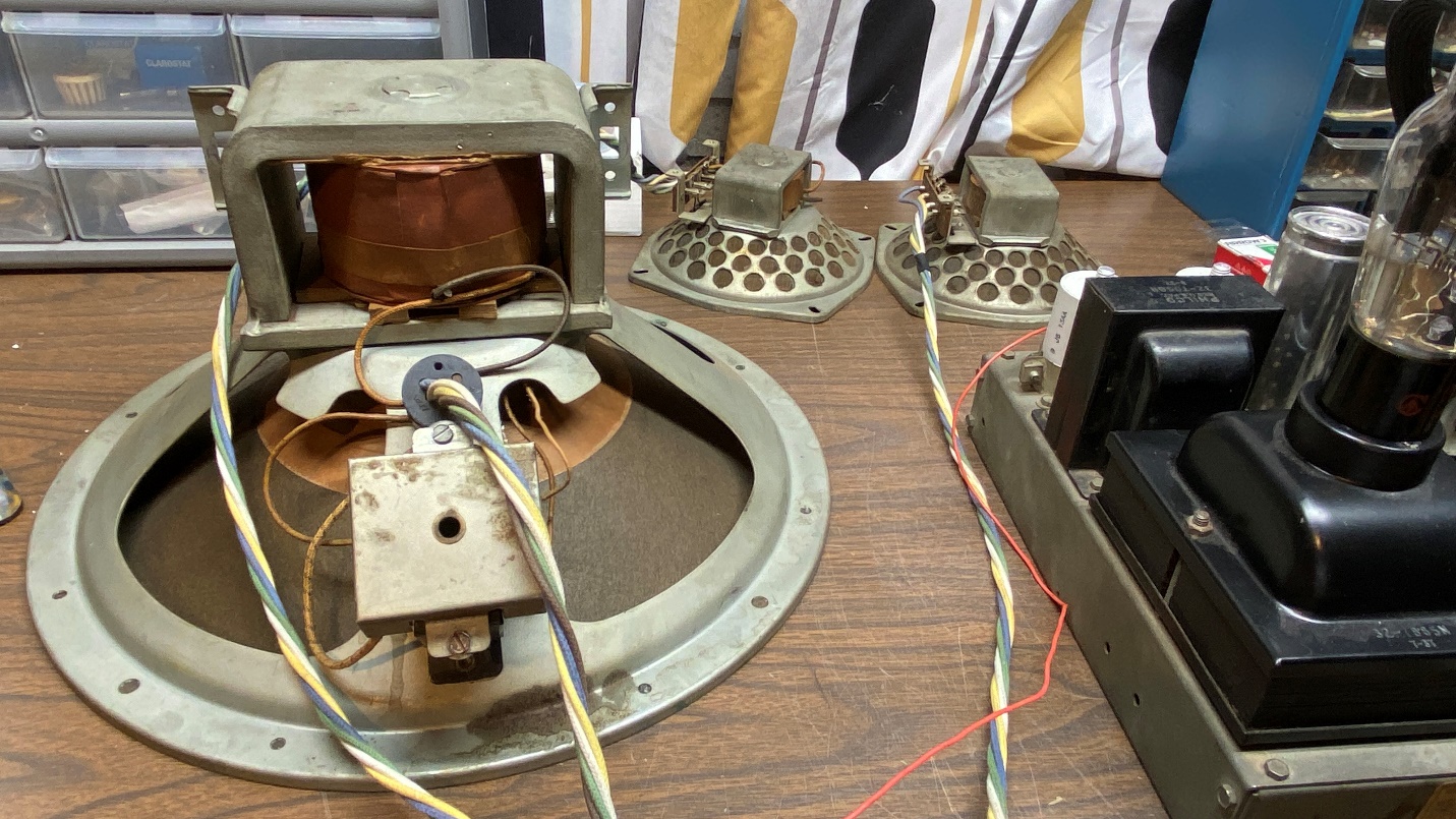
The 38-690 woofer and tweeters, with the amp/power supply chassis at right.
I informed the owner of all these developments. He advised me to stop and not work on it any more since the radio was working again. I am going to follow his wishes.
So that is it for this 38-690. I am disappointed that I was unable to build a 1937 RF unit as a “standby” RF unit. But as you recall from the first several installments of this series, that RF unit developed the popping and sizzling problem (which indicates a likely carbon track). Fortunately, I was able to repair the 1938 RF unit which was already inside the radio and it seems to be working ok.
Now to move on to other projects!